
stan2004 posted:
Adrian! posted:
 
Also...  You know those chokes all of us are putting in series with the power supplies to keep the RF impedance high? Under a short circuit transient those are going to cause a massive di/dt event at the TIU too...
 

Good point.  If you open the TIU you will see such a choke at the Voltage In connectors.  A short circuit current on a TIU output channel flows thru the TIU choke.  So the di/dt phenomenon, for lack of a better term, is the same as the passive-mode TIU when adding the choke between the PSX-AC and the track.  Same choke application - to keep the RF impedance high to protect the DCS-signal integrity.

Consulting some power electronics folks (not me) the proper terminology is "Inductive kick-back".

CAPPilot posted:
GGG posted:

Theory versus practice, you guys are going to start scaring people.

I got rid of all my older TIUs and now have only Rev L versions (two primary and one backup).  Following this topic got me wondering if I should sell my Rev Ls and go back to older ones.  Now G has me wondering if I should keep my Rev Ls and hope for the best (he did state an unfixable TIU may of had this problem).

Here is my power setup for each TIU channel:

I'm using more power but have a much faster CB (PSX) and a large choke (34A 22uH).  For you experts that know what you are talking about, is this setup more or less susceptible to the failure you are talking about.  If it is more susceptible I may get rid of the Rev Ls.

Circuit analysis suggest that having the 22uH makes the situation worse not better.

The PSX is going to cut the power really fast, which means the current is going to turn off through the choke really fast, which means the slope of the current in the choke is really steep, which means the voltage across the choke and TIU (V=Ldi/dt) is going to be very big.

Hi All,

If you aren't an EE (yet) and really really want to understand this stuff I found a very short / clear video tutorial that absolutely nails it in two parts. The first is 12 min and covers the basics, the second is 7 min and explains the TIU situation exactly.

Kickback part 1
Kickback part 2

It'll make this entire thread crystal clear in a few minutes.

Sorry, I'm an Educator and can't help it.

Adrian! posted:

The PSX is going to cut the power really fast, which means the current is going to turn off through the choke really fast, which means the slope of the current in the choke is really steep, which means the voltage across the choke and TIU (V=Ldi/dt) is going to be very big.

Adrian,

Thank you for the feedback.

So with the choke I have a higher probability of failure, without the choke I have signal interference between the PSX and TIU.

I could remove the PSX/choke but that would put a full 20 amps to the track with the lessor circuit protection of the Legacy 360 PowerMaster, not ideal for my purposes.  (NOTE: I do want 15+ amps so lets not go further off topic discussing the pros/cons of that.)

Not sure MTH's fix will help that much, so no real solution for me unless John's circuit proposal fixes the issue while still allowing me to maintain my current power setup. 

An unknown for me is how fast is the internal circuit protection of the Legacy 360 PowerMaster.  I've not heard anything about this.  Probably not as fast as the PSX but maybe fast enough.

May see some Rev Ls for sale on the forum shortly.

CAPPilot posted:
Adrian! posted:

The PSX is going to cut the power really fast, which means the current is going to turn off through the choke really fast, which means the slope of the current in the choke is really steep, which means the voltage across the choke and TIU (V=Ldi/dt) is going to be very big.

Adrian,

Thank you for the feedback.

So with the choke I have a higher probability of failure, without the choke I have signal interference between the PSX and TIU.

I could remove the PSX/choke but that would put a full 20 amps to the track with the lessor circuit protection of the Legacy 360 PowerMaster, not ideal for my purposes.  (NOTE: I do want 15+ amps so lets not go further off topic discussing the pros/cons of that.)

Not sure MTH's fix will help that much, so no real solution for me unless John's circuit proposal fixes the issue while still allowing me to maintain my current power setup. 

An unknown for me is how fast is the internal circuit protection of the Legacy 360 PowerMaster.  I've not heard anything about this.  Probably not as fast as the PSX but maybe fast enough.

May see some Rev Ls for sale on the forum shortly.

If you're worried but don't want to open anything.... you could always put TVS diodes across the choke instead of in the TIU?

Hello Everyone! This discussion although pretty much over my head (as in making my head spin like Beetlejuice) is intense and very informative.

But it also jogged my memory about a TVS discussion that occurred back in September 2014 (link is here https://ogrforum.ogaugerr.com/...ge-protection?page=1).

This discussion touched on the topic of adding TVS diodes to the engines; effectively stopping the electrical issues at their source.

I am committed to doing that because I value my collection and the electronics required to run my trains reliably without chances of hurting their sensitive electronics.

My question is....WHERE within the locomotives is the best place to install the TVS diodes. I'm not an EE, but I am pretty handy, a **** good solderer and learn quickly. It would be great if someone could provide a little more detailed direction as to where the TVS diodes need to go. I read in the other discussion the TVS diode should go as close to the power pickups as possible. I'm guessing the TVS diode has to bridge from the frame (ground) to the center pickup somewhere correct?

Your input would greatly appreciated 😁

GRJ, your comment well above about the auto ignition coil is only partially right.  There is induction in a coil (that rapidly burned contact points---I've replaced many every 10,000 miles) but it is only the primary of a transformer-type the power to which gets broken by the contact points.  The output of the secondary windings has the real high voltage.

Now, well before your time, there were make-and-break systems........

RJR posted:

GRJ, your comment well above about the auto ignition coil is only partially right.  There is induction in a coil (that rapidly burned contact points---I've replaced many every 10,000 miles) but it is only the primary of a transformer-type the power to which gets broken by the contact points.  The output of the secondary windings has the real high voltage.

Now, well before your time, there were make-and-break systems........

We used to toss someone a loaded capacitor aka condenser from these point sets..when they caught it ZAP.

RJR posted:

GRJ, your comment well above about the auto ignition coil is only partially right.  There is induction in a coil (that rapidly burned contact points---I've replaced many every 10,000 miles) but it is only the primary of a transformer-type the power to which gets broken by the contact points.  The output of the secondary windings has the real high voltage.

Now, well before your time, there were make-and-break systems........

Remedial reading is required, my comment is correct.  The collapsing field in the primary does generate significant current and it has significant voltage as well.  Yes, the collapsing magnetic field generates an even larger voltage in the secondary (at much lower current) simply because it has lots of fine windings.

Just got the boards back from OSH Park, I'll build up a few of them.


This time the components are right, but I did forget to change the 1.6mm to .8mm for the board thickness.  Doesn't affect the function, but I don't see any reason for them to be that thick.  Just holding the board up to the ACT244, it looks like it lines up as intended.

Attachments

Images (2)
  • mceclip0
  • mceclip1

I am a rank amateur on most electrical components John, I have just enough experience tinkering with blown computer boards and PCB's to know that I have plenty of dumb questions, but also know keeping from blowing a component or board is worth asking a few dumb ones. I solder and fix with diagrams and others experience as much as I can, you probably will never catch me trying to prototype or build new and great additions, but I CAN conduct and successfully complete old tech once learn to do it.

If you want a logistical or operational function to be run, I would be the one leading the charge.

I have found that working with our "Science and Technology" folks in the club, and the wizardry displayed on this forum, I am not always lost in what happens, just don't hand me a schematic and ask for an intelligent interpretation of it.

I thought it was time to check out one of my TIU's, so I pulled one out of the box, it's a couple year old Rev. L. 

HOLY COW!  Even though this is barely used, the signal amplitudes are all over the map!  Suddenly, it makes sense that we're seeing all sorts of issues with TIU signals.  Hard to believe they came from the factory like this, three of the four channels have much lower signal output.  I was using this one for a couple of years, but it didn't really get a lot of actual running time for my carpet central.

It's time for me to test all my TIU boxes and start soldering I suspect.  I can't wait to see how ugly the club TIU's are, I didn't realize things went south this quickly!

Fixed Output #1

Fixed Output #2

Variable Output #1

Variable Output #2

The test setup is dirt simple, just a transformer feeding all four channels of the TIU with the simple filter that Adrian posted.

Attachments

Images (5)
  • mceclip0
  • mceclip1
  • mceclip2
  • mceclip3
  • mceclip4
gunrunnerjohn posted:

I thought it was time to check out one of my TIU's, so I pulled one out of the box, it's a couple year old Rev. L. 

HOLY COW!  Even though this is barely used, the signal amplitudes are all over the map!  Suddenly, it makes sense that we're seeing all sorts of issues with TIU signals.  Hard to believe they came from the factory like this, three of the four channels have much lower signal output.  I was using this one for a couple of years, but it didn't really get a lot of actual running time for my carpet central.

It's time for me to test all my TIU boxes and start soldering I suspect.  I can't wait to see how ugly the club TIU's are, I didn't realize things went south this quickly!

Exactly!!! Did you see the log sheet at the top of this post? With the tiny TVS in there these things last a few days tops.

Last edited by Adrian!

1. What DCS signal packet are you showing?  The watchdog?

2. Are you next going to remove the apparently under-sized clamp diode (in the TIU to confirm the signal returns to "full" amplitude?  The idea being that for the test purpose, there is no need for protection.  I believe the theory is the existing diode is slowly shorting itself over time with the repeated "hits" from track voltage transients.

3. Is there a way to put a TIU channel into Protocast mode without an engine on the track?  I think a big stumbling block for the average home setup (vs. a club) is the need for an oscilloscope to capture the short DCS bursts.  I believe if a DCS channel can be made to broadcast the more active Protocast signal, it ought to be possible to modify the filter with $1 or so of parts so that a reasonable proxy for the signal level could be displayed on any DC voltmeter.

stan2004 posted:

1. What DCS signal packet are you showing?  The watchdog?

2. Are you next going to remove the apparently under-sized clamp diode (in the TIU to confirm the signal returns to "full" amplitude?  The idea being that for the test purpose, there is no need for protection.  I believe the theory is the existing diode is slowly shorting itself over time with the repeated "hits" from track voltage transients.

3. Is there a way to put a TIU channel into Protocast mode without an engine on the track?  I think a big stumbling block for the average home setup (vs. a club) is the need for an oscilloscope to capture the short DCS bursts.  I believe if a DCS channel can be made to broadcast the more active Protocast signal, it ought to be possible to modify the filter with $1 or so of parts so that a reasonable proxy for the signal level could be displayed on any DC voltmeter.

Ohhhh. i can speak to some of this.

#2 On one of the club TIUs after I removed the under-sized clamps and forgot to put the mod on.  (IE there were only 3/4 channels protected). After about a week of running we had the ACT244 die. Once that was replaced it was good as new though.

#3.  It's not so easy. I've been trying to make an envelope detector. The DCS packet is half 0s, and so short in duration that it's hard to see. If the channel is working and there's 8 volts of swing then you can see something with a fast diode rectifying into a small cap (but it's noisy of course). If you have reduced excursion to a volt or two, really there's nothing to see as the energy of the packet is too low compared to the output referred noise of the diode/cap pair.  The only compromise I've found that works okay is this cheap USB scope. (still $80) It can capture packets okay, but it's a bit software intensive to use since it really only comes with a .h C library and a python library. I can post code if anyone wants it.

#3.  But if the DCS signal can be made to be continuously "on" or at least more frequently on, doesn't that effectively turn an envelope detector into a level detector?  Protocast mode is capable of sending live audio over the track (encoded into DCS packets of course).   So now we're talking thousands of packets per second.  There may be other DCS modes that also put more packets on the track per second...again keeping in mind the idea is a procedure that the average user can employ with minimal hoop-jumping. 

stan2004 posted:

#3.  But if the DCS signal can be made to be continuously "on" or at least more frequently on, doesn't that effectively turn an envelope detector into a level detector?  Protocast mode is capable of sending live audio over the track (encoded into DCS packets of course).   So now we're talking thousands of packets per second.  There may be other DCS modes that also put more packets on the track per second...again keeping in mind the idea is a procedure that the average user can employ with minimal hoop-jumping. 

I use the casting mode for debugging actually. It still looks about a 10% duty cycle packet:no-packet. I assume this is done on purpose so other engines on the layout can still communicate in the gaps.

I couldn't find an easy way to keep the DCS going all the time, I think having something to capture it such as a real 'scope is probably going to be required.  Even a 10mhz single-trace 'scope would be sufficient for comparative amplitude measurements, you just want to see if the signal is there and the amplitude.

Stan, I was simply triggering on a packet and pressing the whistle button to force the display.  I don't think this has ever been back to MTH for the fix, but I'll bite the bullet and pull the board out and look on the back.

*************************** EDIT ***********************************

No TVS parts on the back side, this one is a virgin.

Last edited by gunrunnerjohn
gunrunnerjohn posted:

I couldn't find an easy way to keep the DCS going all the time, I think having something to capture it such as a real 'scope is probably going to be required.  Even a 10mhz single-trace 'scope would be sufficient for comparative amplitude measurements, you just want to see if the signal is there and the amplitude.

Stan, I was simply triggering on a packet and pressing the whistle button to force the display.  I don't think this has ever been back to MTH for the fix, but I'll bite the bullet and pull the board out and look on the back.

*************************** EDIT ***********************************

No TVS parts on the back side, this one is a virgin.

One Trick I sometimes use:

If you fire single pulses into the TIU port (like 1-2us width with 5V excursion), it replies with a packet.  (555 Timer does the trick).

John,

Given the fact that all that's connected to the output is the 'scope probe after the 60hz filter, where exactly is the TIU getting a return answer for the track signal?

Given that there isn't a powered engine on the tracks, I'd expect that the test would run, however, that it would return a "0" value, since no packets out of each 100 would be acknowledged.

Are you sure there isn't a PS2 or PS3 board installed in that 'scope?  

Last edited by Barry Broskowitz
Barry Broskowitz posted:

John,

Given the fact that all that's connected to the output is the 'scope probe after the 60hz filter, where exactly is the TIU getting a return answer for the track signal?

Given that there isn't a powered engine on the tracks, I'd expect that the test would run, however, that it would return a "0" value, since no packets out of each 100 would be acknowledged.

Are you sure there isn't a PS2 or PS3 board installed in that 'scope?  

Hi Barry,

Step 1 of the test is to put the PS2/PS3 board into "test" mode. That doesn't happen if there's no board. It just sends some packet to say "is there a train out there" then quietly waits...

I guess, in that case, I have one good channel.   This is the only one that gets over about 11 volts and lower.

Barry Broskowitz posted:

John,

Barry, my question is how did it determine the track signal was a 10?

I have no idea. As I said, I would have expected a "0", meaning zero ACKs received.

I think I cracked that mystery.  I set the remote into SPEED mode so I wouldn't keep complaining about not finding the engine, that probably affects how the test responds.  When I go back to NORMAL mode, the test just hangs as I'd expect if it doesn't find an engine.

Attachments

Images (1)
  • mceclip0
Adrian! posted:
gunrunnerjohn posted:

Adrian, since you've been looking at these for some time, what is the P-P voltage of a properly working chip?  Is it like the highest amplitude on my previous post, or should I be expecting more?

Should be about 14 to 15V pk2pk new out of the box.

As we already have a 1,2,3,   I will use A, B ,C

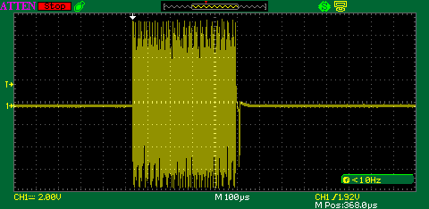
A) If we are trying to define a base line of a good DCS Signal output, do we need to define which DCS signal we are measuring?  When I tested the clubs TIU's and new out of the box TIU's, I test the watchdog signal produced from pressing the "start up" button on the hand held and I get readings  in the 17-19 vpp range.  Pictures below are from my 3 year old home TIU which I just took.  Are my setting off on the scope?   Question resolved, in the pictures below there is a spike at the end of the signal burst that the scope picked up, which increased the readings by 4-5v.  Without the spike the readings are in the 14-15v range.  Thanks GRJ!  When the intensity of the scope is turned up the spike is quite evident.  Need to go back to old school and read the picture and not the number readings on the digital scopes.

B) In one of the above responses it talks about removing the MTH installed TVS to get full signal back.  Would this work?  From my understanding TVS's fail either in an open or short condition not in a quasi short condition.

C) I also have run into TIU ports which have reduced output.  What is the easiest way to test the ACT244 chip to see if it is the cause of the reduced power.

Bob   D


DS1Z_QuickPrint13DS1Z_QuickPrint14

Attachments

Images (2)
  • DS1Z_QuickPrint13
  • DS1Z_QuickPrint14
Last edited by rad400

Add Reply

Post
The DCS Forum is sponsored by

OGR Publishing, Inc., 1310 Eastside Centre Ct, Suite 6, Mountain Home, AR 72653
800-980-OGRR (6477)
www.ogaugerr.com

×
×
×
×
Link copied to your clipboard.
×
×