gunrunnerjohn posted:
Adrian! posted:
gunrunnerjohn posted:

I'm just wondering if there isn't a much simpler solution here.  As far as the TVS, how about forgetting the silicon diodes and just putting one of the big honkin' 3kw TVS diodes right across the gates and dispense with the diodes.  It'll take a much bigger beating than the 500W ones that you were testing with, and with the adapter board, it should be easy to piggyback on the existing ACT244.  I'm thinking of something like this Littlefuse SMDJ7.0CA.  Hard to believe it couldn't stand up to a fair amount of punishment.  It's small enough to perch right on top of the ACT244 on a little PCB.


Uh some details. The scope is looking at the output side of the transformer, not the waveform right at the clamping device/ACT244 driver output pins. Clamping from 0 to 7 volts could work but again it's got to be quick quick quick. A small zener or TVS is faster than a big zener since Cj is the dominant term in the time constant which grows with anode area.

Maybe a small TVS in parallel with a big TVS?

I missed this in all the responses.   That's not a bad idea, I think I'd make the small TVS just a bit higher in voltage so that when the big one did clamp, it takes the stress off the smaller one.  What do you think, a 500W one like you used and the 3000W one?

Any chance you could equip one of your TIU's with this combo since you have the ideal testbed?  Or, maybe we can get Bob at NJ-HR to try this fix.  If we can come up with a working fix that only has a couple of components, it would be easy to make the piggy-back board that could be plopped on top of the 244's.

I checked the 3000W one I specified, it has a pretty decent response time, and the added capacitance of the little board should be minimal if we do it right.

Fast response time: typically less than 1.0ps from 0V to BV min

I bet it'll work. You'd want a small split, maybe 9V big and 9.2V small... something like that.

Steinzeit posted:
Well, I had read this thread from the start.   As I understand it, you installed the PSX units on Nov 16th at the same time as a new group of ex-factory Rev L 's were installed.  But you've never operated any channel as I've described as I understand your posts;  that is, PSX + non-TVS L's -- have you ?

SZ

I have not tired that configuration....you can try it, but I'm not sure the thinking is correct.

The PSX-AC stops the high current from the power supply during a short but the effect that damages the TVS and drivers is when the train derails the motor inductance dumps a big voltage into the track. This is because the voltage across a coil/inductor (IE motor windings) is the slope of the current through it (V=LdI/dt)... so when the current jumps from the short the voltage jumps and stresses the ACT244 drivers. The TVS tries to limit this voltage. Since the energy causing the failure originates from the coil, not the power supply, it's unlikely the PSX-AC can do anything to change the situation. Our layout is in passive mode so that high current doesn't pass through the TIU anyways. 


Adrian! posted:
gunrunnerjohn posted:
Adrian! posted:
gunrunnerjohn posted:

I'm just wondering if there isn't a much simpler solution here.  As far as the TVS, how about forgetting the silicon diodes and just putting one of the big honkin' 3kw TVS diodes right across the gates and dispense with the diodes.  It'll take a much bigger beating than the 500W ones that you were testing with, and with the adapter board, it should be easy to piggyback on the existing ACT244.  I'm thinking of something like this Littlefuse SMDJ7.0CA.  Hard to believe it couldn't stand up to a fair amount of punishment.  It's small enough to perch right on top of the ACT244 on a little PCB.


Uh some details. The scope is looking at the output side of the transformer, not the waveform right at the clamping device/ACT244 driver output pins. Clamping from 0 to 7 volts could work but again it's got to be quick quick quick. A small zener or TVS is faster than a big zener since Cj is the dominant term in the time constant which grows with anode area.

Maybe a small TVS in parallel with a big TVS?

I missed this in all the responses.   That's not a bad idea, I think I'd make the small TVS just a bit higher in voltage so that when the big one did clamp, it takes the stress off the smaller one.  What do you think, a 500W one like you used and the 3000W one?

Any chance you could equip one of your TIU's with this combo since you have the ideal testbed?  Or, maybe we can get Bob at NJ-HR to try this fix.  If we can come up with a working fix that only has a couple of components, it would be easy to make the piggy-back board that could be plopped on top of the 244's.

I checked the 3000W one I specified, it has a pretty decent response time, and the added capacitance of the little board should be minimal if we do it right.

Fast response time: typically less than 1.0ps from 0V to BV min

I bet it'll work. You'd want a small split, maybe 9V big and 9.2V small... something like that.

I was looking at the large and small TVS units, it's tricky trying to match two of them as with the same maximum, they have widely different voltages they'll begin to clamp at.  Are you really saying that the 1 picosecond response of the 3000W part is too slow?  I still wonder if we can't just use the large one, makes the whole job a ton simpler as far as trying to select parts that will play well together.  I have a bad feeling that even with picking the correct specifications, that the mis-match may put too much of the load on the smaller TVS and still cause the same issue of it shorting.

I'm still kinda' stuck on the simple solution, one big TVS right on the 244.

Adrian! posted:
bigdodgetrain posted:
Adrian! posted:
bigdodgetrain posted:
GGG posted:

If you build this board build in a LED light that illuminates when the TVS Shorts.  While the design is meant to prevent the TVS shorting rapidly, I am sure after enough hits even the new one will short.  Since it doesn't show up as a power short, like the input/output TVS, but will degrade DCS signal (which might not be detected on a small layout) a LED would be nice.  It must be serviceable easily also.

Lastly, there are plenty of REV L TIU out there with out this TVS mod form MTH.  Therefore your TIU is not susceptible to this exact failure.  Your failure will be the Transmitter chip. 

Most people do not have the issues this San Diego club has.  I have repaired plenty and they have not come back.  Frankly, I probably only worked on a few (less than 5), that had the TVS mod.

So the sky is not falling.  But this mod may make the Rev L TIU much more robust.  G

not sure you have the correct club mentioned.

ADRIAN! is from the angels gate Hi-railers which is outside long beach calif.

However the san diego 3 railers is having the same issue.

Yup I'm from the angel's gate Hi-railers' club in San Pedro. It's like a big test-bench.  At one time I thought about joining the San Diego club but don't tell anyone though.

if you fix our issue I will make you a deal you can not pass up!

I think step one is to establish that weak signals really are the issue you are experiencing. San Diego is not *so far* so maybe I can pay a visit with my test gear and have a look for you. The TIU you have is a Rev L with the USB port on the side right?

correct.

Adrian! posted:

2. If the original tiny TVS fails and sits that way for more than a few minutes (like a day) then the ACT244 is usually damaged too (since it's been sending commands to a short circuit instead of a train).

I got the impression from the above statement that the 244 is primarily damaged by longer term, more steady state conditions -- perhaps that is not correct.  I just did want to point out that MTH engineering added the TVS to correct a problem that MIGHT not exist as a practical matter  with the PSX-AC in the circuit [ since their engineering / evaluation etc presumably did not take such a device into account ].   There is no question your beefier solution is better from just an engineering standpoint, but that's why I was suggesting a TVS-less board + the PSX -- that's all.

SZ


Adrian

thank you for all the research on this. We are on our third generation of 6 tius. There is two problems with the rev l. The first one we noticed is the power fets on the variable channels blowing the installation of the psx seems to prevent that now.  The signal disappearing is something we never figured out without just replacing with a new one. It will be awesome to have the fix for that now.  We do have a scope at the club but never recorded everything to the extent you did. Thank you thank you thank you

Steinzeit posted:
Adrian! posted:

 .........Some members have brought Rev L TIUs from home recently bought and installed and I've found the same TVS failing also.

1.  Well, GGG, he also wrote the above.  You don't suppose those members let children play on those home layouts, do you ?

2.  If prolonged shorts are the 244 killer, wouldn't the best "control" test be Rev L boards with no [ 244 ] TVS protection BUT the newly purchased front end units [ PSX-AC ] that GRJ recommended ?  I don't he tried that combination.

SZ

Kind of a smart alec response too.  But what is the sample size.  10 damaged out of a 1000?  Do you know?  Some folks are heavy handed on there layouts.  Some running 20-60 amps in parallel on the layout.  SO what do you think happens when a derailment occurs.

MTH added the TVS to help save the Transmitter.  Unfortunately it seems to have it's own higher failure rate under heavy hits.

Why would MTH design with other product used before or after.  Frankly some of this stuff is kool aid, as Adrian has explained.

But again, plenty of folk operate there trains with no issues, but yes, repetitive and long term shorts and derailments will damage trains and transformers.  Period.

Nothing here has made the claim of average use doing this.

Let see what MTH will do, but some of this is like saying I race my Toyota Camry in the Baja 5000 and the shock and tires broke and the motor is worn out, and it is only one year old, let's sue Toyota.

Small sample sizes, and small amount of folks that have TIU failures.  But it does happen.  Again, like just about everything else around here folks take it to the extreme.  G

gunrunnerjohn posted:
GGG posted:

If you build this board build in a LED light that illuminates when the TVS Shorts.

Easier said than done.  Without some extra components, I don't see any way to do this.  Extra components means more expense for each board as well as a larger board that may not fit on top of every ACT244 in all the TIU versions.

Stop whining and just do it, make it worth all this effort with an easy detection method.  Folks are not buying O scopes for the home layout:-)   G

Steinzeit posted:

I got the impression from the above statement that the 244 is primarily damaged by longer term, more steady state conditions -- perhaps that is not correct.  I just did want to point out that MTH engineering added the TVS to correct a problem that MIGHT not exist as a practical matter  with the PSX-AC in the circuit [ since their engineering / evaluation etc presumably did not take such a device into account ].   There is no question your beefier solution is better from just an engineering standpoint, but that's why I was suggesting a TVS-less board + the PSX -- that's all.

It's easy to suggest all this extra analysis be done by someone else. If this topic is really important to you, have you considered doing some testing to augment our understanding of the scope of the problem?  Any additional data points would be very useful at this stage.  Personally, I think Adrian has done more than his share!

Nothing is so easy as the job you imagine someone else doing.

GGG posted:
gunrunnerjohn posted:
GGG posted:

If you build this board build in a LED light that illuminates when the TVS Shorts.

Easier said than done.  Without some extra components, I don't see any way to do this.  Extra components means more expense for each board as well as a larger board that may not fit on top of every ACT244 in all the TIU versions.

Stop whining and just do it, make it worth all this effort with an easy detection method.  Folks are not buying O scopes for the home layout:-)   G

Nothing is so easy as the job you imagine someone else doing.

Might I suggest something fun!

Here's a circuit design challenge for all the smart folks here...

Draw up a 9V battery powered handheld tester that plugs into the TIU outputs with dual a banana clip cable and just tells you if the DCS levels are good (>10V), medium (5-10V) or bad (<5V) with a green, red and orange LED. Like the TMCC signal car one, but for DCS. Keep it under $40 for the BOM. I'd be curious what other people come up with. Remember you need to extract the DCS from the AC track power first! Keep the BOM under $50 or no one will care...

Some hints: I already looked at basic and active Vf compensated diode envelope detectors, but the SNR sucks too much to go into a comparator because the packet duration is so short (duty cycle <0.5% and even in the active time its half 1s and half 0s... so there's not a lot of energy). The comparator directly is also not good because the slew rate of discrete packaged comparators is lousy compared to the DCS CDMA symbol rate.

Last edited by Adrian!
gunrunnerjohn posted:

Adrian, did you see my suggestion to simply use a 3000W TVS and eliminate the diodes?  I wonder if that would be robust to make this a "one component" solution?  After all, there can't be that much energy constantly bombarding the 244's, or they'd be failing all over the world.  As George points out, while we do see them failing, it's not a avalanche of them as a rule.  I'm just wondering if the part was robust enough, it would absorb whatever punishment was being dished out by the signal transformer kicking back to the 244's.

Do you have the schematic to confirm the protection device is truly across the actual 244 output pin(s)?  One issue we have seen with DCS signaling is managing capacitance - capacitance is a "known" DCS signal killer.

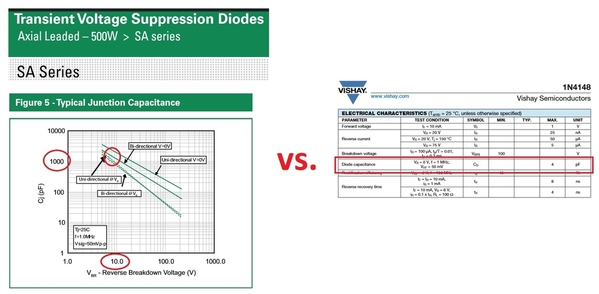
A TVS or Zener diode can have substantially more capacitance than a generic silicon diode.  From the datasheets, the 1N4148 capacitance is less than 5pF whilst the 500W TVS is over 1000pF.  And by stacking multiple 1N4148 diodes in series, the capacitance is reduced even further.

capacitance may be the issue

Attachments

Images (1)
  • capacitance may be the issue
stan2004 posted:
 
Do you have the schematic to confirm the protection device is truly across the actual 244 output pin(s)?  One issue we have seen with DCS signaling is managing capacitance - capacitance is a "known" DCS signal killer.

A TVS or Zener diode can have substantially more capacitance than a generic silicon diode.  From the datasheets, the 1N4148 capacitance is less than 5pF whilst the 500W TVS is over 1000pF.  And by stacking multiple 1N4148 diodes in series, the capacitance is reduced even further.

capacitance may be the issue

Hi Stan,

It is across the ACT244, according to what I was shown.

You're right on the capacitance eating the slew rate of the driver though. Lets do the math together to check GRJ's idea!

The ACT244 datasheet says the typical case device is 6.5ns TPLH and 7.0ns TPLH with a test condition 50pF external load.

So MTH gangs 4 of them together so let's assume the Thevnin equivalent of the output is 4X better than a single chnanel.. so that's lets say an average Tpd of 6.8ns /4 = 1.7ns. (I know that's an ideal case but it's okay enough for order of magnitude considerations).

Everything is RC time and scales linearly so here's some orders of magnitude:

100pF would be 3.4ns

 500pF would be 17ns Tpd time

1000pF would be 34ns Tpd time

 5000pF would be 170ns Tpd time

DCS has a rate of 3.75 MHz. Let's just call it 4 MHz so math is easy. which is 250ns Tsymbol.  Now to have a nice square wave you want TPLH+TPHL to be < 1/10 of Tsymbol ... or roughly

250ns / 10 > 2Tpd

so thats 25ns > 2 Tpd

so Tpd < 12.5ns

So calculating the specification 12.5/17 X 500pF = 367pF, so lets say 350pF.

Therefore don't pick a TVS or collection of circuits that presents more than 350pF total capacitive load to the ACT244 outputs.

Cool.

Adrian! posted:
stan2004 posted:
 
Do you have the schematic to confirm the protection device is truly across the actual 244 output pin(s)?  One issue we have seen with DCS signaling is managing capacitance - capacitance is a "known" DCS signal killer.

A TVS or Zener diode can have substantially more capacitance than a generic silicon diode.  From the datasheets, the 1N4148 capacitance is less than 5pF whilst the 500W TVS is over 1000pF.  And by stacking multiple 1N4148 diodes in series, the capacitance is reduced even further.

capacitance may be the issue

Hi Stan,

It is across the ACT244, according to what I was shown.

You're right on the capacitance eating the slew rate of the driver though. Lets do the math together to check GRJ's idea!

The ACT244 datasheet says the typical case device is 6.5ns TPLH and 7.0ns TPLH with a test condition 50pF external load.

So MTH gangs 4 of them together so let's assume the Thevnin equivalent of the output is 4X better than a single chnanel.. so that's lets say an average Tpd of 6.8ns /4 = 1.7ns. (I know that's an ideal case but it's okay enough for order of magnitude considerations).

Everything is RC time and scales linearly so here's some orders of magnitude:

100pF would be 3.4ns

 500pF would be 17ns Tpd time

1000pF would be 34ns Tpd time

 5000pF would be 170ns Tpd time

DCS has a rate of 3.75 MHz. Let's just call it 4 MHz so math is easy. which is 250ns Tsymbol.  Now to have a nice square wave you want TPLH+TPHL to be < 1/10 of Tsymbol ... or roughly

250ns / 10 > 2Tpd

so thats 25ns > 2 Tpd

so Tpd < 12.5ns

So calculating the specification 12.5/17 X 500pF = 367pF, so lets say 350pF.

Therefore don't pick a TVS or collection of circuits that presents more than 350pF total capacitive load to the ACT244 outputs.

Cool.

For those that want to know what we're talking about...

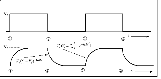
-->beyond the protection the TVS or other diode provides to the ACT244 driver, it also adds capacitance to the wire/cable.

The driver cannot deliver infinite power to the wire/cable (obviously) so it has some limit to how much current it can deliver at any moment. For design we usually model this with something called a Thevenin resistor which is a resistor in series with an ideal voltage source.

Under normal operation, as the driver switches between the ones and zeros of the data signal the ACT244 has to charge up and discharge this added capacitor through that resistor. So the time it takes to charge up and down depends on how much capacitor there is to charge, and how much series resistance there is to limit the current. We express the total delay of charging as an RC time constant. As the time constant gets longer, the time it takes go between 1 and 0 gets longer so the "square wave" data gets less square. It turns into an 1st order exponential function. So in the figure below... as the diode gets bigger and bigger and adds more and more capacitor to the wire.... the curvy part gets wider and wider as a percentage of the overall waveform width until it just doesn't work.

The equations in terms of "RC" are in there if you want them. Units are in seconds. For DCS the distance between 1 and 2 is about 250ns, so you'd want the up + down curvy part < 25ns (a tenth of the total width) so it still looks sort of squarish to the decoder.

RC_time

Sorry I'm an educator. I can't help it.

Attachments

Images (1)
  • RC_time
Last edited by Adrian!

Adrian, And a fine educator you are!!!!  Wow, that takes me back to my college days in the mid '70s.  Most of my 42-year career has been spent deploying black boxes that I don't need to remember all the electronics I learned.  I am interested in this topic, though I only have a layout room that is less than 12 feet square.  I only envision ever using one TIU, but perhaps I will need a second one someday.  I will not be running many trains at a time.  Thank you again for bringing this to our attention and describing it in an easy to understand way! 

OK, Stan has an excellent point, and it kinda' throws a monkey wrench into using either of the TVS devices we're been talking about!  Truthfully, I didn't consider the capacitance, and for low voltage parts, it's significant.  Even the 500W one at around 10V breakdown can be over 1000pf, and of course, the 3000W one is a lot more!

Junction Capacitance for Littlefuse SA5.0A 500W TVS

Junction Capacitance for Littlefuse SMDJ7.0CA 3000W TVS

It's back to the drawing board...


Attachments

Images (2)
  • mceclip0
  • mceclip1

FYI, I opened my early Rev L last night and found no TVS's installed. I think I purchased mine within a couple of months of their release. This was before folks were reporting failures. No problems so far. I couldn't find a suitable DC supply nor parts to make a high pass filter so didn't measure signal strength but will do that this weekend. If I find mine is still good I suspect I will pass on any additional protection. I am using a TMCC Lock On for a fast breaker.

Stay tuned.


Pete

Last edited by Norton

I just checked my vintage Rev L and all signals are strong. Again this one has zero TVS's like Adrian's has. 

I would suggest this "fix" by MTH has unintended consequences. Maybe some here may come up with a better mouse trap but in the meantime those with weak signals might just want to remove the TVSs and make sure you have fast breaker along with the accepted TVSs at the track connection.

Pete

Last edited by Norton

Hi Adrian !   This will be my 1st post here in a good many years, and I would NOT have known about any of the "GREAT" reading on this thread were it not for so many (mostly off YouTube) telling about all this. That said: I think this could be the genesis of some revolutionary things *(amid the little "gremlin's" we've had for all these years !).  I myself personally, have had no "real" issues UNTIL my counterpart and I decided to "try" the WiFi stuff ... and when we DID, it was the undoing of all GOOD things FOR US. 

We've ALWAYS used remotes for our Layout, and after we loaded 6.1; "the sky FELL".  Since that upgrade, we went from utter "perfection", to a system that STILL plagues us to this very moment. With several hundred engine's that once numbered almost 1,000 (in the "good ole days after we kinda "sold-off" our stuff), we regularly operated 10 engine plus consists when never under a hundred cars IN those very consists with again, near PERFECT control, and we always spank "10's". Combine this with 9 tracks, amid many multiple's on every track, and it was always a smooth-sail ... "until now"

Anyway, all our TIU's are "L's", and to this day (with 30 and some having 40 amp channel's),  I've said (for years now) that IF you want life's "acid-test" ... "I'm your man". I RUN my stuff (that's why I bought it), and until that (which I preface in the above) occurred, we WERE "Golden". While the "WiFi" worked (and very nicely), we NOW shut down what WERE great running consists, only to return to everything being literally "gone". ME ?  "I'm not very 'techey' and I myself just liked what we had, (along with 'some' tiny "gremlin's"), but all this makes MANY want ta see a light, amid revisiting this entire "ordeal" with what I have read here !. Tho we run in passive, I've watched my engine's "spark" for years while they fight to pull the long consists I demand they pull ... and again: I have NEVER had a TIU issue, "UNTIL- NOW".

Final thought:  we'd ("well me anyway"),  would just like 4.2 back, and for me "it just has ta WORK" ... BUT NOT THIS. Like Ben, Mike, and a good many others that 'push this stuff to the hilt', I will be VERY interested in whatever the "resolve" HERE turns out to be !.  After that: you get a great big WOW as your the REAL Ambassador, and a GREAT asset toward the hobby !. *(John your right there to !) ... Kudos Guy's !.  As you fan-base  G R O W S,  I'll be looking-in, amid all of the "busyness" going on here with hi-hopes and LOTS of optimism !!. 

Tho I myself am kinda on the "outs" (with trains), it STILL would be nice to occasionally re-visit an operating session or to with NO issue's.

K E E P  U P   T H E   G R E A T   W O R K  ! ! !    


Norton posted:

I just checked my vintage Rev L and all signals are strong. Again this one has zero TVS's like Adrian's has. 

I would suggest this "fix" by MTH has unintended consequences. Maybe some here may come up with a better mouse trap but in the meantime those with weak signals might just want to remove the TVSs and make sure you have fast breaker along with the accepted TVSs at the track connection.

Pete

I do have at least one of the first version L TIU. I use the Lionel 180 bricks that seem to trip for anything. I lost the smoke control on my ps3 Allegheny and they tripped. It pulled my Z1000 on my bench right down yet no tripping.

So maybe my success with my other TIUs is because of those ph180 bricks?

Here's a good start on the project.

In the schematic, both U1b and U1c are amplifying the current sense signal.  U1c, the "overload" detector, has a gain of 148, but it is slowed down by the resistor and capacitor on its output.  The time constant (RxC) is 2.6 seconds.  Multiple short hits to this RC combination would charge it up until it trips the relay latch.

U1b has a gain of 37, which means it requires 4 times as much current, but it acts instantaneously for "dead short" situations.

Lionel Powerhouse 180 Schematic

Attachments

Images (1)
  • Lionel Powerhouse 180 Schematic
RJR posted:

I agree with you, GRJ, on your evaluation of the PH180 breakers.  I wish that some talented soul would design and sell a DIY kit to assemble such breakers, to use on train layouts.  [HINT HINT]

A few already have. The Lionel TMCC Lock on is every bit as fast and unlike the 180w brick, is self restting. Also you have DCC specialties PSX-AC. Even better as the current trip point is setable up to 15 amps and it can be used in conventional mode. No need to reinvent the wheel.

Pete

Last edited by Norton

Barry, that may be true but I have installed my Lock on between the Transformer and the TIU. I use a TVS between the TIU and track. Recall its the transformer that produces the destructive spikes not the engine and the TVS should handle the rest.

I checked my nearly 8 plus year old REV L and signal is still strong so assume this protection scheme is working.

Pete

Pete, I do not use lockons or TMCC, and the PSX is too pricey.  I use breakers on many circuits, for trains and for accessories.

"Recall its the transformer that produces the destructive spikes.."  That is generally not correct.  The spikes are generated by the sparks your see---actually, when the current makes and breaks rapidly such as in a rolling derailment, the various coils on the circuit, such as loco motor windings, through inductance create voltage spikes.  No breaker on a transformer output can control these.

Barry Broskowitz posted:

Pete,

The Lionel TMCC Lock on is every bit as fast and unlike the 180w brick, is self restting. Also you have DCC specialties PSX-AC.

I'd heard (but not verified) that there were issues with signal degradation when using either one of these devices with DCS. Could you provide any insight in that regard?

Thanks!

I heard this too but I can confirm its not true.

I'm setup with the 1 PH180s + 1 PSX-ACs for each of 20 TIU channels. The DCS excursion voltage, rise time all that is identical with the TIU on the bench, and the TIU powered by these protectors. This is true in active mode, and passive mode (as long as you have a grj-choke placed in series)

Norton posted:

I just checked my vintage Rev L and all signals are strong. Again this one has zero TVS's like Adrian's has. 

I would suggest this "fix" by MTH has unintended consequences. Maybe some here may come up with a better mouse trap but in the meantime those with weak signals might just want to remove the TVSs and make sure you have fast breaker along with the accepted TVSs at the track connection.

Pete

After I saw your thoughts, I will run one like just to see actually just to see if it makes it through 7-8 hours of being beaten on.

The part I still don't know is what happened exactly that prompted the TVS diodes to be added to later Rev L boards. Someone at MTH did a lot of soldering to put those in there post-fab.

gunrunnerjohn posted:

Here's a good start on the project.

In the schematic, both U1b and U1c are amplifying the current sense signal.  U1c, the "overload" detector, has a gain of 148, but it is slowed down by the resistor and capacitor on its output.  The time constant (RxC) is 2.6 seconds.  Multiple short hits to this RC combination would charge it up until it trips the relay latch.

U1b has a gain of 37, which means it requires 4 times as much current, but it acts instantaneously for "dead short" situations.

Lionel Powerhouse 180 Schematic

It's a transient detector (LC series) instead of a current detector (R series). D4 and D3 protect the OPAs from the voltage transients. I'd guess they clamp at a much lower voltage then we're looking for though.

Andrian, beside Ben and the New Jersey Hirailers, other have replaced their REV Ls with older versions and been OK as long as fast breakers are in place. I don't have a lot of derailments but enough along with broken shorted equipment to test the TIU. My layout is also my test track and many items come to me for repair have short circuits. 

BTW when I had the cover off my TIU I noticed it has a number of 20 amp automotive fast blow fuses. I assume MTH must think their TIU should handle up to that so a 10 amp fast breaker should be more than adequate.


RJR, how much do you think someone else would have to charge to design sell at a profit another fast breaker. I suspect it would be more than 50 bucks which is what  the others sell for now.

Pete

Last edited by Norton
Norton posted:

Andrian, beside Ben and the New Jersey Hirailers, other have replaced their REV Ls with older versions and been OK as long as fast breakers are in place. I don't have a lot of derailments but enough along with broken shorted equipment to test the TIU. My layout is also my test track and many items come to me for repair have short circuits. 

BTW when I had the cover off my TIU I noticed it has a number of 20 amp automotive fast blow fuses. I assume MTH must think their TIU should handle up to that so a 10 amp fast breaker should be more than adequate.


RJR, how much do you think someone else would have to charge to design sell at a profit another fast breaker. I sispect it would be more than 50 bucks which is what  the others sell for now.

Pete

I guess it makes sense if you don't have the TVS inside the TIU it won't fail to short. That does mean the ACT244s are taking the voltage then. They have ESD clamps on-die so they aren't completely defenseless.

Do note though, we're not talking about current as the failure mechanism. The failure is caused by the Ldi/dt voltage that develops from the train motor inductance. This is what the TVS are there to clamp on.

Add Reply

Post
The DCS Forum is sponsored by

OGR Publishing, Inc., 1310 Eastside Centre Ct, Suite 6, Mountain Home, AR 72653
800-980-OGRR (6477)
www.ogaugerr.com

×
×
×
×
Link copied to your clipboard.
×
×