


I finally got some time to get down the basement again and got some wires run from the transformer to barrier blocks on the upper level, one for switch fixed voltage operation and the other for low voltage accessory power.
Good work!


Originally Posted by pennsyfan:
Originally Posted by trumptrain:
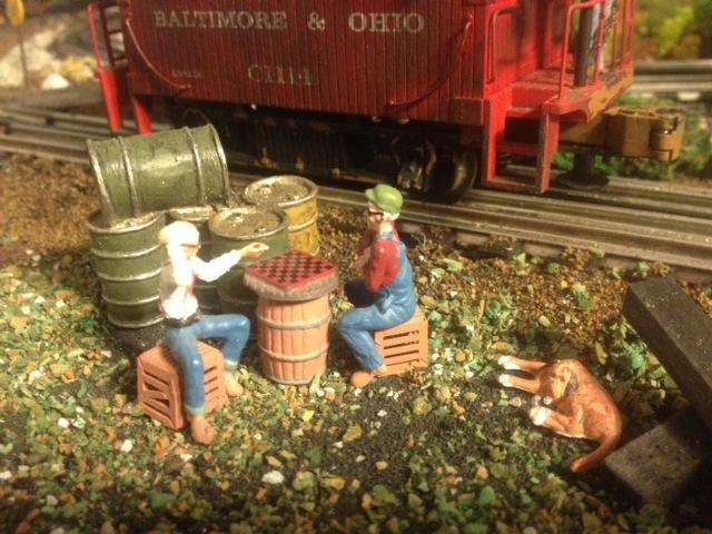
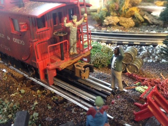
I've been quite busy working on the Mountain Division of the Free State Junction Railway since my last post.

Pat,
Excellent scenery work! That B&O SF-43 combination Boxcar/Caboose is awesome; I snagged one of them at York back when the Yellow Hall was still active.
Bob, Thanks so much for your kind compliment. I'm happy you liked the photo. Yes I love this combo caboose as well. As soon as I saw it I just had to have it ![]() I weathered it and now use it here on the Mountain Division. Glad to hear you have once of these combos as well!
I weathered it and now use it here on the Mountain Division. Glad to hear you have once of these combos as well! ![]()
Tonight I ran my Railking Y6 on the Mountain Division. Placed a windmill behind the barn and tried out different locations for my Marx postwar water tank on the Mountain Division. Really cool to see that Y6 trundling over the Bollman Truss bridge. I'll try to get some photos up soon.
Just got in a few minutes on that mill I started some days ago...I had previously dabbled a number of colors over all the stones with a brush, and today I used a bigger brush to spread a thin wash of gray over all to weather and insure all walls are the same general tone. Not much progress...
ON THE GLACIER LINE TODAY 3-14-14.
03-14-2014 The road crews are fast! In one day, they built the road across the tracks and also paved main street in Cataract.


Attachments
Images (4)
Finished staging yard which has morphed into a 3 track stub end passenger terminal. Installed the last of the RK block signals so now there are simulated signals and I know if something is on the track in locations that are out of site. Weather is getting nicer so need to finish installing 3 caboose industries ground throws, stacking foam for a hill to hide where track penetrates a wall and installing track ballast before calling it a winter.
I also managed to put some small signs up around the layout as well as pick stuff up again!
GOOD GOD I thought I was going to turn into a skeleton for a minute.Originally Posted by John C.:
Worked on the interior of a church building that will be set high in the mountains. It is loosely based upon our own home church, but looks like some of the first churches built near Glacier Park on the exterior. My wife "stained" a few windows...more today with photos later...train show starts in one hour.
c.sam,
i'll second that.
jackson
THE GLACIER LINE UPDATE:
03-14-2014 The road crews are fast! In one day, they built the road across the tracks and also paved Main Street in Cataract. I cut a piece of hardboard to replace the balsa wood floor in our church. I also cut out paper and covered the park benches and painted them brown to make them look like church pews.
03-15-2014 I continued to paint the floor. Connie Coy detailed the top two church windows to look like stained glass. We both glued down the interior pieces onto the new hardwood base. The main aisle way in our church resembles our real life church, St. Stephen's Lutheran Church in Plainfield, Indiana.
You aren't there yet Pastor Robert C. Rohrman!


Attachments
Images (4)


John,
The church looks fantastic! Connie did a wonderful job on the stained glass! The last view looking in from outside is really great!
That gives me a great idea. as a thread was going on the forum earlier this winter, every layout needs a church. I of course, have always had one, but will need a new one in O gauge. My idea is like you. to build a church reminiscent of the church Kim and I were married in 30 years ago. While we moved a year later to Virginia, then West Virginia, we have been back in Butler, about 18 years, and are with our old congregation. Also, the old building was too small, and was torn down a couple of years after our wedding for a larger one. The church has old photos of the original building , and we have some, so I could do a descent job. It was a unique building, so it would look good on the layout, when I get that going.
Thank you.
I looked up Plainfield Indiana. I see it is right off I70. I traveled right past you twice driving to my company's headquarters in Mattoon, Illinois. I don't know if I will ever go there again, but if so, I will at least lean over the driver, and blow the horn. ;-)
Mark:
If you ever find yourself out this way again please contact me if you'd like to see the layout in person. We are actually "between" Plainfield and Avon, Indiana. From the I-to interchange at Plainfield, you are 15 minutes from our house.
Originally Posted by Mark Boyce:
I looked up Plainfield Indiana. I see it is right off I70. I traveled right past you twice driving to my company's headquarters in Mattoon, Illinois. I don't know if I will ever go there again, but if so, I will at least lean over the driver, and blow the horn. ;-)
John,
I don't travel much, but one never knows. I would love to meet you and see your layout, if the chance ever comes.
Thank you,
03-16-2014 on THE GLACIER LINE
Connie outlined and began to paint the area of Cataract. Today it was mostly just blue sky. I went through the hassle of vacuuming up a bunch of ballast, probably about three feet total, to install some wires that will enable the flashing cross bucks to function automatically as trains pass through the main roadway crossing in Cataract.
Thank God! I didn't glue down my ballast or this would have been a disaster. I simply vacuumed up the ballast, installed two “trip” wires, one on each track that will lead to a Dallee Electronics circuit board that will make the signals flash and also activate a bell sound. Of course, I didn't think about this before I put the ballast in the first place, because there was no way to know that Connie and I would be offered two very nice cross bucks for five dollars each!
That’s why when building model railroads I try to construct everything in such a manner so that when changes or upgrades come it is easier to make the changes. If the ballast and track would have been glued down I would have literally had to rip/tear out the track and roadbed and wiring and start from scratch! Of course if we wouldn't have stumbled onto this fabulous deal it wouldn't have been a problem either!


Attachments
Images (4)
Originally Posted by John C.: John, Your track work and roads look great!!!
What kind of ballast do you use? Looks fantastic!![]()
ON THE GLACIER LINE TODAY 3-14-14.
03-14-2014 The road crews are fast! In one day, they built the road across the tracks and also paved main street in Cataract.
Jo
This morning I spent some time getting the train room ready for visitors. I had the kids next door and their dad over to see Mount Randolph and the Mountain Division. The were pretty darn amazed!! The last time they visited all that was there was a couple 2 by 4 braces for the mountain. They really enjoyed seeing the Y6 smoking up a storm too.
03-17-2014
I ordered the MTH crossing gates with sound from LINCOLN, NE today for $59.99; which is a good price but bad because these are nowhere on the priority list. I thought that we had gotten a great deal on the two signals we purchased not realizing I’d have to but another electronic piece to make the gates work. A piece by itself, with no sound, ranges from $20 to $30. After this discovery I thought to myself why am I going to buy just a circuit board to make the lights flash when for $30 more than that, $60.00 total, I can get: a sound system, a circuit board and two more crossing gates? This became a no brainer less laying out $70 for stuff I don’t need, but farther down the road are nice details.
Secondly, because we now will have four crossing bucks, I stretched the Cataract road out farther than originally planned to have it cross the tracks on the far end town. I think the nice long curve looks nice.


Attachments
Images (4)
I was getting really bored with grass laying so I laid out a new addition to my layout-a bump and go trolly line! I always wanted to have parallel tracks; however, due to my space constraints I never thought it would be possible until I saw trolleys being advertised and I found some old track from an RTR set!

Attachments
Images (1)

Working on a cliff along with a wooden trestle bridge.

Attachments
Images (1)
More wiring!
")
Peter
Attachments
Images (1)
")
We had a track laying party on Saturday. This is the unfinished side of my attic. There are double mainlines entering and exiting this area. At each end are #4 turnouts feeding a doubleslip switch. This breaks the track out to two mains plus a center passing siding. The 0138/0128/0120 curves at the far end are super elevated a scale 3" (1/16") and are spaced at 4.5" O.C.
This area is approximately 14x18'. Even with two halogen work lights, it's hard as the dickens to get decent lighting. From the pictures, I can see I've got a tweak or two to straighten out a couple of my runs. All told, we ran about 90' of track. It's exciting to finally get some track down.
Special thanks to Jerry and Dexter for their assistance.


Attachments
Images (6)
Looking Great Gilly!
I have neglected to post photos of the work going on at our club layout. It's fairly large with three loops and an elevated run that is separate from the lower mains.
We have created a gorge and one member is working on a trestle to span a river over and through it.
The orange arch bridge came from my old home layout.
Here is the temporary plywood support while we await the installation of the trestle itself.


Attachments
Images (2)


THE GLACIER LINE UPDATE: Second update today!
Connie Coy was a busy bee tonight! She extended the back drop painting about 12 to 13 feet. This is just the basic outline and fill. There are many more levels of detail to be added to this area. This is Cataract where the recent pictures have been of me installing a road and preparing for the flashing cross bucks with sound! It looks very different with all of the buildings removed.


Attachments
Images (5)
Originally Posted by chefnme:
I was getting really bored with grass laying so I laid out a new addition to my layout-a bump and go trolly line! I always wanted to have parallel tracks; however, due to my space constraints I never thought it would be possible until I saw trolleys being advertised and I found some old track from an RTR set!
Your trolley line will really add something to your layout and your growing town. Looks great!
I recently purchased a bump and go trolley (Pittsburgh Railways of course). I put it up on the Ceiling Central using Gar Graves track and bumpers. The problem with the Gar Graves bumpers was that every few times, the bumper on the trolley would get stuck under the rail cross brace of the bumper. It was that close of a fit. Must have been designed by Murphy.
I modified the bumpers by gluing a tie under the rail. It works fine now. When I finally get to build my layout, I will come up with a better looking scheme.

Attachments
Images (1)


I was very lazy today. There's a whole bunch of stuff going on unrelated to trains that has my attention today. I did go down and brainstorm my next plan-of-attack which is to get two of the four upper level hidden staging loops in operation. All I need is one more turnout and a few more strips of track, plus building the support structure. Hopefully this will be accomplished in the next few months--wires and all!
I went downstairs for the first time in a few days. Didn't spend long, but got a couple things done. Finished the wiring on the last of the control panels. Now all 4 are ready to install.
I also hooked up a strip of LED's to one of the circuits I built following forum member RailRide's design.
RailRide's original design.
My perf board mounted version.
Williams Superliner from the early 90's. I have 2, six car sets of these that need conversion.
Not bad.
I bought enough parts to do 50 cars.
Attachments
Images (4)

Originally Posted by Big_Boy_4005:
I went downstairs for the first time in a few days. Didn't spend long, but got a couple things done. Finished the wiring on the last of the control panels. Now all 4 are ready to install.
I also hooked up a strip of LED's to one of the circuits I built following forum member RailRide's design.
RailRide's original design.
My perf board mounted version.
Williams Superliner from the early 90's. I have 2, six car sets of these that need conversion.
Not bad.
I bought enough parts to do 50 cars.
Nice! I tried to send u few emails and never heard from you. Please check ur emails. Thanks!
Patrick, I've been checking and checking looking for your email. Got nothing. Was starting to worry about you. Tammy got no texts either.
Wednesday and Thursday are still open.
Sent u emails twice. I'll be at ur place this Thursday. My internet n mobile are down.
Sounds good Patrick, see you then.
Former Member
Test run my new AC9 in the bar. It's a Sunset 3rd Rail, and yes, it cost as much as the new VL BigBoy and don't even have a smoking whistle... ![]()
and I don't even have any guard rails up there!
FULL HD...go big screen!
The AC9 is off the chart! Awesome!
What a great engine. Definitely a winner.
well I'm the odd ball here..I have a carpet layout for now,until we move into a bigger appartment or house...but its better then nothing at all....its 11x18...I had to re wire my PRR S1 unskirted duplex made by 3rd rail..going to upgrade it to TMCC shortly...here a video of it running..running high balling...but had the sound off to show a guy how smooth it runs but can hear the belt wine in it...its like hearing a blower on a car..because of the wide cog belt.....sound neat to me..S1 with a blower..lol..I do take a section of track down by the kichen and hall way so nobody cant step on the track...video was taken with my samsung s4 cell phone..laidoffsick I love your setup..!!..thats what I'm hoping to do someday..
Finally, I am hooking up some of my Miller Engineering signs.


Attachments
Images (2)


For the first time in 3 weeks Patrick came over, and we actually did some construction.
The new hidden yard is now ready for track!
Just like the old hidden yard, the new hidden yard is situated on a reverse loop.
Trains will travel past the yard, around the loop, then into one of the 7 tracks.
Next week is going to be crazy, Jon (Mill City) on Tuesday, Matt on Wednesday, and Patrick on Thursday. The goal is to get the hidden yard laid and powered, so the temporary cutoff can be removed once and for all. Shooting for the end of April.
Attachments
Images (3)
Elliot, I see you and Patrick got a lot done. I'm afraid to ask where all the "STUFF" that was in that corner ended-up. Looks great. See-ya Tuesday.
It went to a number of different places. Unfortunately, not enough of it went in the trash. Don't worry there's plenty left.![]()
I am starting the process of working on my bridge that will be on the curve coming out of my passenger terminal. I am thinking that I want a curved stone arch bridge that is loosely based on the one in Minneapolis. The first step is experimenting with cardboard mockups to determine the sizes and shapes of the arches. Here is a picture of the first attempt.

Attachments
Images (1)
Former Member
Very good Start, Art. Having looked at the real thing you are duplicating, you sure are on the right "track".
Thanks, Brian. It has been pointed out to me that the real bridge has more elliptical arches, but I'm not sure that that is important. Here are a couple pictures of the real bridge that is in Minneapolis. It's not important to me to make an exact copy of this bridge, but I want to follow it loosely. I decided to also post these on the weekend photo fun.
Art


Attachments
Images (2)
Art, this is a model of the Stone Arch Bridge at the Twin Cities Model Railroad Museum. I hand painted every stone 25 years ago. This model doesn't include every arch. I think the real one has 22. But the arches it does have are the correct proportion, which give it the look of the real thing.
As long as you are still working with cardboard, you might want to try fewer, wider arches.
Attachments
Images (1)
Elliot - That is a beautiful model! I would love to learn more about how it was constructed. I am also interested in how the water was done too. Is it still there? Thanks for sharing the picture.
Art
I didn't build the bridge. It was done by 3 generations of the same family. It's made from basswood strips that were textured, then applied over a superstructure. Around the arches, individual pieces were hand fitted. The club is open to the public.
You should get a group of the Chicago guys and come up for a visit. Maybe even take the train.![]()
Art....your mock-up looks good. I would be very interested in your construction ideas. I am considering building a curved arch as well and was considering Masonite board.
Rick
Art
if you want elliptical arches then you would need to cut one from wood or masonite to use as a template for the others. Once cut, dont worry about exactness if you intend to cover the arch with stone because you can create a "negative" of the curved- elliptical shape to use as an under arch form to help set the stone for each arch.
Art....
The arches that support my city are made from pink insulation foam sheets. It was as simple as drawing out the design directly on the foam and then cutting it. From there you can paint and weather to your taste and then use a soft lead pencil to draw a block or brick pattern. The pencil creates the mortar joints and a relief to the surface. The foam can be bent into graceful curves, etc..... The picture below, even though it is not in a bridge form as you intend, shows the finished arches for the city....
Alan


Attachments
Images (2)
Alan
those spans supported by the Lionel supports are cute! Please replace at your next opportunity or I will send the bridge police over to your house to remove!
underground bus station. When enlarging the town to accept the Woodland Scenics buildings I added an under town bus station (MTH Greyhound) that connects to the train station and has a ramp road leading up to the town ( not yet connected).
The RR crossing "decals" are from Red Lion ($5.00).

Attachments
Images (2)

Art
See how Alan has done his elliptical arch. A simple but elegant concrete with just arch stones around the opening arch then using stone for the supports going down.
Rick - I am thinking that I will make the basic shape out of 1/8" Masonite. It is bendable enough yet will have a lot of strength when it is curved. I most likely will then cover it with thin foam and then use a pencil to "carve" the stones on it. Please share your ideas and progress so we can all learn from it.
Alan - Thanks for your input. Your a tough act to follow, but I appreciate your suggestions.
Alan - I am going to have to try an elliptical pattern and see how it looks. I know it looks great on the real bridge in Minneapolis, but I also like the look of the first cardboard template too. Another decision is whether to lower the entire bridge? It is currently designed to be 12" high. A taller bridge would be more dramatic, but is it worth the trouble to redo all the bench work in this area? I'm thinking not, but am interested in your opinions.
Art
Former Member
Elliott:
That is a fabulous arched bridge. You sure have painting skills.
Alan...thanks! Actually, the stone supports are Woodland Scenics HO retaining walls. They are plaster castings that I stained with....are you ready?.....ground cloves from my wife's pantry!! Yep, took the stark white castings and put them in a bowl of water, added the powdered cloves and heated the mixture up in the microwave. Let them sit for about 10 minutes or so and the result turned out great. ( I remembered from past experience that cloves stain clothing quite well..LOL!!)
Alan
Alan
The stone support supporting the lift bridge are great. It's the other Lionel elevating supports sitting atop those concrete bridge bases aah not so much! If you are going to use the Lionel elevated supports then cut off the base so they dont overhang the bridge support and add your own base plates then sit those on the bridge supports.
However, employing the many concrete plastic bridge bases, we all have that come with each MTH and Lionel Bridge, in any way, is a fabulous testament to "waste not want not."
Alan...OH..OK, I thought you were referring to the supports on the arches. Yes, I have to agree with you. I was trying to come up with something different for the approach bridge supports going to the lift bridge and came up with the idea of using something I already had. I don't like them all that much either and have for quite some time thought about changing them. As a matter of fact, I have some nice MTH stone supports that I am working on right now so keep your eyes posted, a change may be in the near future!!
Alan
Alan
Definitely. You hired a mason for most of the work in that area so give him/her some extra work doing the supports.
Originally Posted by Passenger Train Collector:
Elliott:
That is a fabulous arched bridge. You sure have painting skills.
Thank you, but I'm afraid I may have lost them. It took patience and a steady hand back then.
well I did a lot today I think. while at a home store today they had a remeinant of indoor out door carpet so I bought it and brought it home pulled off all the track on the whole layout and began putting it down and cutting it around mountains and and then began reinstalling the track. installed 3 signals screwed down 2 loops of track here's the results.


Attachments
Images (10)
THE GLACIER LINE UPDATE:
This is also a real life history lesson existing today on the top of Marias Pass which is located on the southern boundary of Glacier National Park.
03-23-2014 Connie and I worked on our models of three real life ...objects that are situated in real life in Marias Pass at the summit in a place named: Marias Pass Memorial Square. The three real life objects are:
The Theodore Roosevelt Memorial monument ...... constructed in 1931 honors the president who made forest conservation a national policy. It also marks the 25th anniversary of the U.S. Department of Agriculture, Forest Service. The monument was originally to have been a granite arch spanning the highway. Instead, this obelisk was built. The monument is a tapering 60-foot tall obelisk which resembles the Washington Monument. Its concrete core originally extended 19 feet underground. The seven-inch-thick granite slabs covering the monument were quarried from a source near Helena, the state's capital.
John F. Stevens statue. He was a civil engineer for the Great Northern Railroad. He was charged with finding a suitable rail route across the Continental Divide. In December of 1889, Stevens located and recorded the pass which had been used by area Native Americans for many centuries. By 1893, the Great Northern was running trains over Marias Pass. This route provided the lowest pass (at 5,216 feet above sea level) and the shortest link between the headwaters of the Mississippi River and the Pacific Coast.
William H. "Slippery Bill" Morrison, (ROCK with PLAQUE) claimed "squatter's rights" to the land at Marias Pass. Through diplomatic negotiations by the Columbia Falls Chamber of Commerce and others (including Supervisor Hornby of the Flathead National Forest), Morrison agreed to donate his rights to this land for building a monument to Theodore Roosevelt. Morrison stipulated that no concessions, "hamburger stands" as he referred to them, would be built on any of this property during his lifetime.See More
— with Connie Coy. (9 photos)This is also a real life history lesson existing today on the top of Marias Pass which is located on the southern boundary of Glacier National Park.
03-23-2014 Connie and I worked on our models of three real life ...objects that are situated in real life in Marias Pass at the summit in a place named: Marias Pass Memorial Square. The three real life objects are:
The Theodore Roosevelt Memorial monument ...... constructed in 1931 honors the president who made forest conservation a national policy. It also marks the 25th anniversary of the U.S. Department of Agriculture, Forest Service. The monument was originally to have been a granite arch spanning the highway. Instead, this obelisk was built. The monument is a tapering 60-foot tall obelisk which resembles the Washington Monument. Its concrete core originally extended 19 feet underground. The seven-inch-thick granite slabs covering the monument were quarried from a source near Helena, the state's capital.
John F. Stevens statue. He was a civil engineer for the Great Northern Railroad. He was charged with finding a suitable rail route across the Continental Divide. In December of 1889, Stevens located and recorded the pass which had been used by area Native Americans for many centuries. By 1893, the Great Northern was running trains over Marias Pass. This route provided the lowest pass (at 5,216 feet above sea level) and the shortest link between the headwaters of the Mississippi River and the Pacific Coast.
William H. "Slippery Bill" Morrison, (ROCK with PLAQUE) claimed "squatter's rights" to the land at Marias Pass. Through diplomatic negotiations by the Columbia Falls Chamber of Commerce and others (including Supervisor Hornby of the Flathead National Forest), Morrison agreed to donate his rights to this land for building a monument to Theodore Roosevelt. Morrison stipulated that no concessions, "hamburger stands" as he referred to them, would be built on any of this property during his lifetime.See More


Attachments
Images (9)


John
Cool. Learn something new every day. Look forward to pics when you mount them on your layout.
Doug
Originally Posted by John C.:
THE GLACIER LINE UPDATE:
This is also a real life history lesson existing today on the top of Marias Pass which is located on the southern boundary of Glacier National Park.
03-23-2014 Connie and I worked on our models of three real life ...objects that are situated in real life in Marias Pass at the summit in a place named: Marias Pass Memorial Square. The three real life objects are:
The Theodore Roosevelt Memorial monument ...... constructed in 1931 honors the president who made forest conservation a national policy. It also marks the 25th anniversary of the U.S. Department of Agriculture, Forest Service. The monument was originally to have been a granite arch spanning the highway. Instead, this obelisk was built. The monument is a tapering 60-foot tall obelisk which resembles the Washington Monument. Its concrete core originally extended 19 feet underground. The seven-inch-thick granite slabs covering the monument were quarried from a source near Helena, the state's capital.
John F. Stevens statue. He was a civil engineer for the Great Northern Railroad. He was charged with finding a suitable rail route across the Continental Divide. In December of 1889, Stevens located and recorded the pass which had been used by area Native Americans for many centuries. By 1893, the Great Northern was running trains over Marias Pass. This route provided the lowest pass (at 5,216 feet above sea level) and the shortest link between the headwaters of the Mississippi River and the Pacific Coast.
William H. "Slippery Bill" Morrison, (ROCK with PLAQUE) claimed "squatter's rights" to the land at Marias Pass. Through diplomatic negotiations by the Columbia Falls Chamber of Commerce and others (including Supervisor Hornby of the Flathead National Forest), Morrison agreed to donate his rights to this land for building a monument to Theodore Roosevelt. Morrison stipulated that no concessions, "hamburger stands" as he referred to them, would be built on any of this property during his lifetime.See More
— with Connie Coy. (9 photos)This is also a real life history lesson existing today on the top of Marias Pass which is located on the southern boundary of Glacier National Park.
03-23-2014 Connie and I worked on our models of three real life ...objects that are situated in real life in Marias Pass at the summit in a place named: Marias Pass Memorial Square. The three real life objects are:
The Theodore Roosevelt Memorial monument ...... constructed in 1931 honors the president who made forest conservation a national policy. It also marks the 25th anniversary of the U.S. Department of Agriculture, Forest Service. The monument was originally to have been a granite arch spanning the highway. Instead, this obelisk was built. The monument is a tapering 60-foot tall obelisk which resembles the Washington Monument. Its concrete core originally extended 19 feet underground. The seven-inch-thick granite slabs covering the monument were quarried from a source near Helena, the state's capital.
John F. Stevens statue. He was a civil engineer for the Great Northern Railroad. He was charged with finding a suitable rail route across the Continental Divide. In December of 1889, Stevens located and recorded the pass which had been used by area Native Americans for many centuries. By 1893, the Great Northern was running trains over Marias Pass. This route provided the lowest pass (at 5,216 feet above sea level) and the shortest link between the headwaters of the Mississippi River and the Pacific Coast.
William H. "Slippery Bill" Morrison, (ROCK with PLAQUE) claimed "squatter's rights" to the land at Marias Pass. Through diplomatic negotiations by the Columbia Falls Chamber of Commerce and others (including Supervisor Hornby of the Flathead National Forest), Morrison agreed to donate his rights to this land for building a monument to Theodore Roosevelt. Morrison stipulated that no concessions, "hamburger stands" as he referred to them, would be built on any of this property during his lifetime.See More
John
Cool update and nice modeling.
The rest of you, let's not re-post the photos every time we comment.
jackson
Former Member
Jhainer, that's impressive. How is the I/O carpet to work with?
honestly it was easy. removed all the track laid it down cut to fit . put track back over it. the thing I have found to be a nice feature of it has been the sound reduction in running trains on fastrack. now when I run I can hear the clickity clack of the trucks on the track joints. I did not glue it down the track holds it in place once screwed down. I did leave a small over hang so when I do my facia I can trim to it . another thing I have done this weekend was ran wiring for the signal lights got them somewhat working. and ran longer wire for fastrack switches the longer wire is standard phone line has the same color combo as the fastrack switch wire. I did order switch controllers so I should be wiring that up in the near future. the only thing I don't know how to do yet but have ideas is how to do roads for a city street. do I just place it over the carpet or cut out that area. I would also like to ballast the track but not sure how that would work with the carpet either. here's a video of the train running last night with the lights. they act alittle funny when doing a isolated block 3 in my case do you leave a section that isn't isolated between each block I didn't and I am thinking that might be why the lights are acting funny.
Working on my stone arch bridge and trying to decide on the shape of the arches. A friend made me some elliptical patterns and I cut what I felt was the most promising one out of cardboard to compare it to the first trial. The first one was just using a 4" hole saw for the top of the arch.
Which do you think looks better? What should I do differently?
Art


Attachments
Images (3)
Oh, and while I was at it I managed to get my Milwaukee Road F-3's running again.
When I was trying to run a few trains to show some non-train friends the layout last Saturday night and talking at the same time, I had a "phantom" derailment. My F-3 "picked a switch" that it had run over countless times before with no problem. We all know the "phantom" and "Murphy" show up to help when we have company. Had a bad short and after restoring the power, the engine wouldn't run.
After playing with it today, I discovered that the "phantom" somehow added another engine to my handheld with everything correct except the assigned engine number. After deleting the added engine, everything is back to normal. At least until I have company again.
Art
Former Member
I like the second or wider version.
Chugman,
I agree with Brian, number 2 would be my choice also.
Joe B.
Former Member
Just a personal opinion, Art, but I think you've nailed it with the elliptical arches, they just seem more graceful. Especially with the incline, they just kinda cascade from one to the next. It's all just personal taste, though - I could see someone saying the first ones looked more solid, like a Roman aquaduct. I think a lot of the finished look is going to depend on the details like the size of the stones. I don't see it turning out bad whatever you do, it's a really nice feature.
I wired 4 passenger yard tracks today. I have a bunch of extra 110 light switches left over from the basement work. I have ben using them as track switches to turn power on/off on the yards tracks.
Today I used X10 pushbutton switches. The track would have power when measured with a volt meter. As soon as I would put a lighted car on the track, the power would die. I thought I wired something wrong, but double checked and all was right. I swapped out the X10 switches for traditional wall switches all worked fine.
So I guess the X10 has something in them that the track power does not like.
Ron

Attachments
Images (1)
Originally Posted by Chugman:
Working on my stone arch bridge and trying to decide on the shape of the arches. A friend made me some elliptical patterns and I cut what I felt was the most promising one out of cardboard to compare it to the first trial. The first one was just using a 4" hole saw for the top of the arch.
Which do you think looks better? What should I do differently?
Art
Art,
I agree with everyone else, the second one looks much better, and I think much more prototypical.


Art I have to agree with the Rest of the Guys. I would go with the second one. It looks much better then the first photo.
Completed a depot repaint and re-detail I've been wanting to do for a very long time. You can even read the writing on the bulletin chalkboard if you break out a magnifying glass...
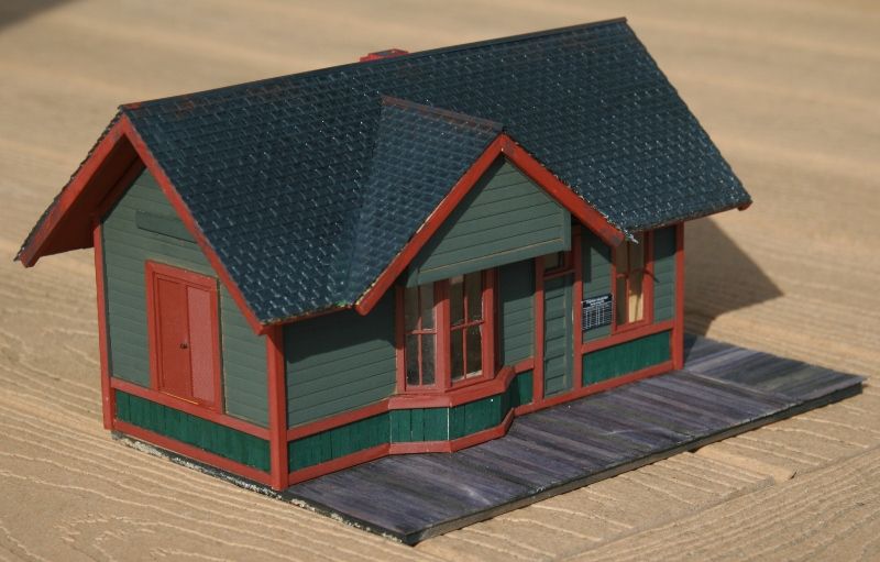
Tough call, Art...both look really good, but I will go against the popular vote and choose the first one. I think I like the fact it will contain more stonework with the narrower arches. You can't go wrong with either design, however.
Rick
Not a lot of progress today, got most of my drops, dropped, lol. Track is back together. Just a couple loose ends to finish putting through the deck and it's on too wiring everything up and getting the second half powered ![]()
Thanks for taking the time to look at my pictures and letting me know what you think. I was thinking that the wider arches looked the best and it appears that most of you agree.
Art
Grandson Cody and I ran wires to the switches on the outside loop tonight next project is running the power for the second loop and then we will have 2 operating loops....hopefully by next weekend.
Originally Posted by Chugman:
Working on my stone arch bridge and trying to decide on the shape of the arches. A friend made me some elliptical patterns and I cut what I felt was the most promising one out of cardboard to compare it to the first trial. The first one was just using a 4" hole saw for the top of the arch.
Which do you think looks better? What should I do differently?
Art
I vote for the elliptical arches.
Originally Posted by Rixster:
Tough call, Art...both look really good, but I will go against the popular vote and choose the first one. I think I like the fact it will contain more stonework with the narrower arches. You can't go wrong with either design, however.
Rick
There is something to be said for both styles of arch. After thinking further about my vote for the eliptical arch, another reason for my preference was that the spaces between the uprights are further apart and show more of what is behind the bridge.
Randy - Thanks for your comment and opinion. That is a good point about exposing more of the scenery under and behind the bridge. By the way, I love your creativity on your logo, nice job!
Art
Originally Posted by Chugman:
Randy - Thanks for your comment and opinion. That is a good point about exposing more of the scenery under and behind the bridge. By the way, I love your creativity on your logo, nice job!
Art
Art:
Thank you for the kind compliment. The logo is my feeble attempt at computer art. My son, Chris, has a friend at school who is a real artist and, in his spare time, is cleaning up the logo.
Randy
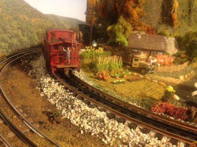
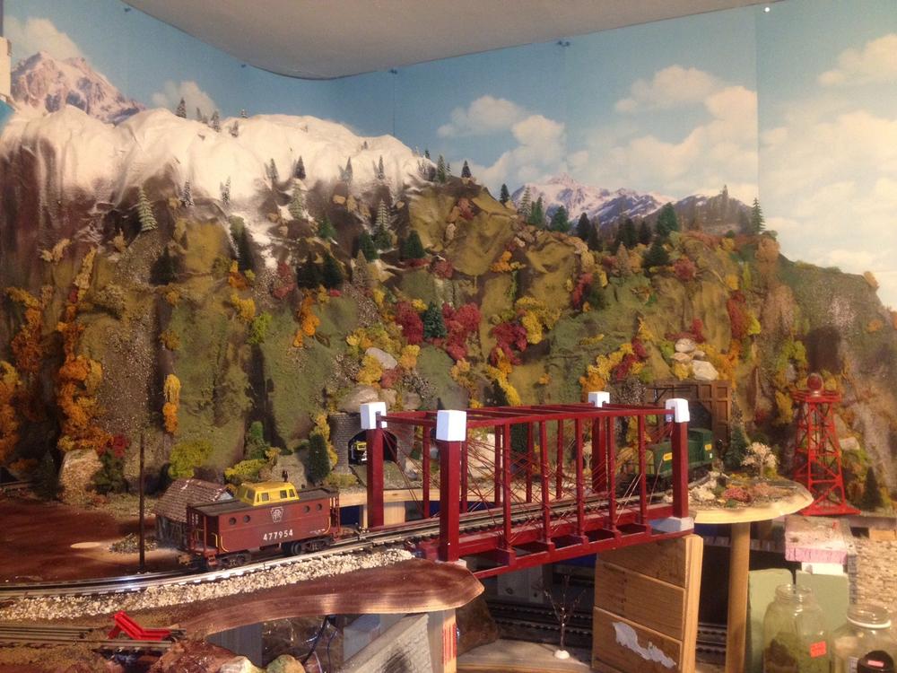
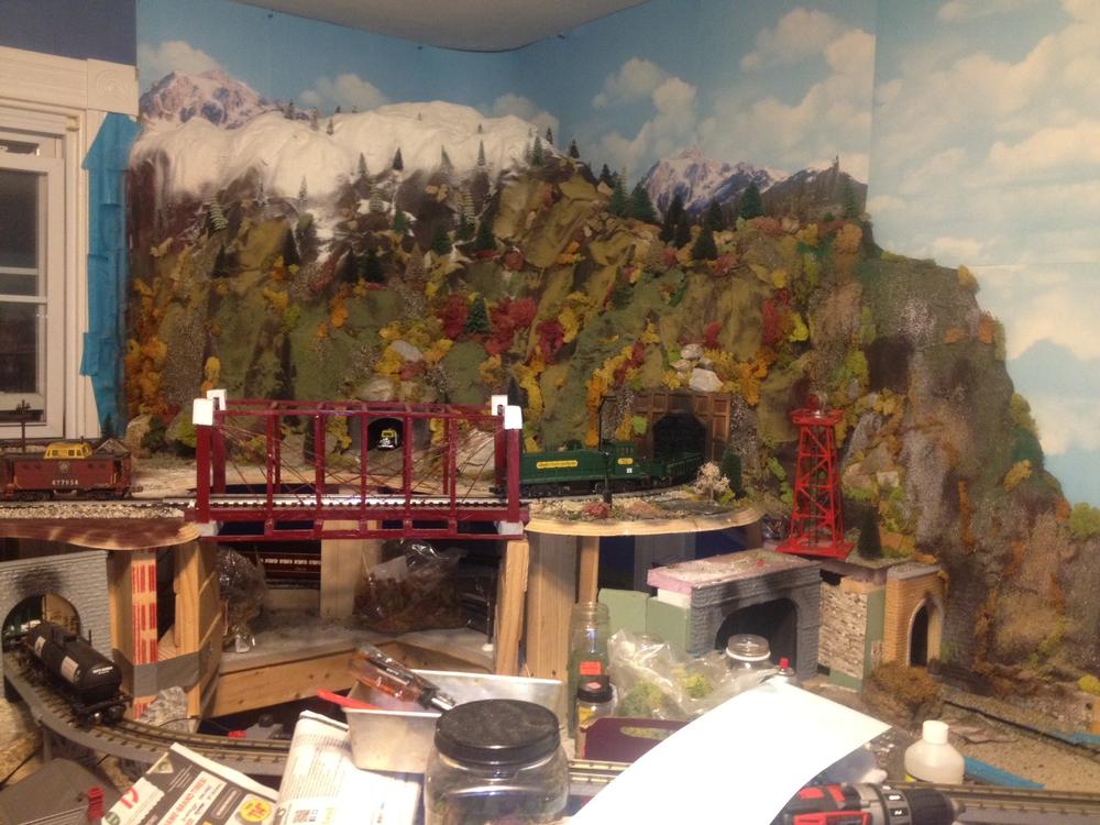
Since my last post, I've built a real stone portal for my trolly line where it enters the underside of Mt. Randolph. I've also used real stone for the hillside that runs along side the trolly line decending from track level of the Mountain Division. The trolly line is entirely elevated on the layout, making for a second level to my Free State Junction Railway which runs above the fictitious town of Patsburg. The east end of the trolly line terminates at a bumper on the inside of the underside of Mt. Randolph. The west side of the trolly line will terminate at Patsburg Westend, a shopping district.
Having the trolly line run inside of Mt. Randolph alludes to the interurban days. i use an Atlas O trolly. ( See accomp. photos )
I used real rocks which I got out of a nearby river bed. I glued the rocks together using Sinbad glue ( great stuff !! ) which I picked up at York. Using Sinbad to glue the rocks together insures there will be no rock slides. ![]()
The top rock over the portal is a long sort of "slab" rock, which fit quite nicely into the space. The portal does not look at all like any "classic" portal, which from my standpoint is pretty cool. As I planned my layout, I did not want to have all of one kind of portal. I want to give visitors the impression that the railroad was constructed over a period of many decades so different kinds of stone, materials, and cuts were employed. At present there are a total of 8 portals on the layout and I use 6 different kinds of portals .... one MTH single portal ( heavily weathered ) for the east portal of Mt. Randolph on the Mountain Division, a Scenic Express wooden portal ( also weathered ) on the west end of Mt. Randolph. For the double track main lines on the bottom deck of my layout I use 3 K line double track portals, an MTH double track portal ... which I had to widen a bit and cut the top higher to accommodate GG1 panagraphs... and a unique looking single portal that I purchased at a local train show.
I hope you enjoy the accompanying photos showing the rock hill, portal, a view of all 3 layout levels, and a Y6 taking the bridge.


Attachments
Images (4)


Originally Posted by p51: Looks great! Nicely done!
Completed a depot repaint and re-detail I've been wanting to do for a very long time. You can even read the writing on the bulletin chalkboard if you break out a magnifying glass...
Originally Posted by Chugman: Both sets of arches you will be great whichever one you decide upon. I do find myself in favor of the wider arches because they do seem a bit more majestic and graceful. I also agree with Randy that the wider arches will allow for better viewing of whatever scenery you have behind the arches. Just my 2 cents. Whichever way you go though your layout will be a winner 
Working on my stone arch bridge and trying to decide on the shape of the arches. A friend made me some elliptical patterns and I cut what I felt was the most promising one out of cardboard to compare it to the first trial. The first one was just using a 4" hole saw for the top of the arch.
Which do you think looks better? What should I do differently?
Art
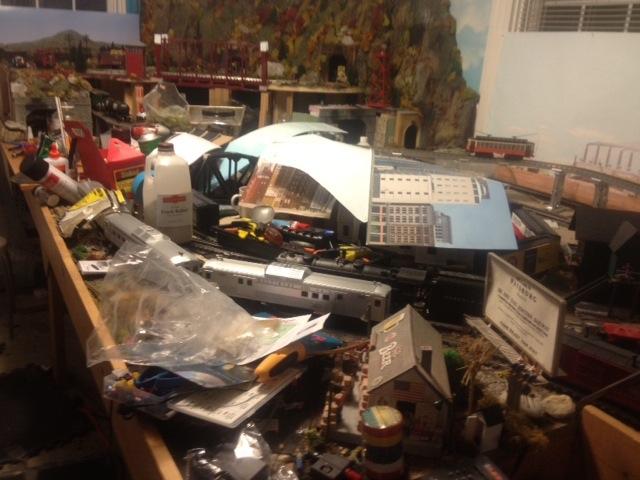
I was busy today. I decided today that before I start on the upper part of my tunnel/mountain I needed to paint the wall in the room blue for sky. also I wanted to finally attach the tunel portals I worked on over the weekend so I did that tonight also. so here is a layout update of sorts. I also ordered a few things in the past few days I ordered 2 sc1 switch controllers and a station with 3 platforms 2 at almost 12 inchs and one at 24 inches.


Attachments
Images (17)
are you doing clouds? I thought of doing them on my walls and putting those glow in the dark stars for at night to give an effect! You have a very nice setup. have fun!
chris
Originally Posted by trumptrain:
Looks great! Nicely done!
Originally Posted by p51:
Completed a depot repaint and re-detail I've been wanting to do for a very long time. You can even read the writing on the bulletin chalkboard if you break out a magnifying glass...
Thanks!
I also have a few new structures, including two single-story farm houses, a water tower and some small sheds.
My layout only exists on paper, I'm waiting for a pal of mine who's offered to help me with my benchwork (I'm going to be building it in sections, so it can be broken down and transported if I ever have to move) for a time he can break out the saws. I have my track plan and am also currently buying up more On30 flex track.
that is very nice. good detail!
Originally Posted by trumptrain:
Since my last post, I've built a real stone portal for my trolly line where it enters the underside of Mt. Randolph. I've also used real stone for the hillside that runs along side the trolly line decending from track level of the Mountain Division. The trolly line is entirely elevated on the layout, making for a second level to my Free State Junction Railway which runs above the fictitious town of Patsburg. The east end of the trolly line terminates at a bumper on the inside of the underside of Mt. Randolph. The west side of the trolly line will terminate at Patsburg Westend, a shopping district.
Having the trolly line run inside of Mt. Randolph alludes to the interurban days. i use an Atlas O trolly. ( See accomp. photos )
I used real rocks which I got out of a nearby river bed. I glued the rocks together using Sinbad glue ( great stuff !! ) which I picked up at York. Using Sinbad to glue the rocks together insures there will be no rock slides. ![]()
The top rock over the portal is a long sort of "slab" rock, which fit quite nicely into the space. The portal does not look at all like any "classic" portal, which from my standpoint is pretty cool. As I planned my layout, I did not want to have all of one kind of portal. I want to give visitors the impression that the railroad was constructed over a period of many decades so different kinds of stone, materials, and cuts were employed. At present there are a total of 8 portals on the layout and I use 6 different kinds of portals .... one MTH single portal ( heavily weathered ) for the east portal of Mt. Randolph on the Mountain Division, a Scenic Express wooden portal ( also weathered ) on the west end of Mt. Randolph. For the double track main lines on the bottom deck of my layout I use 3 K line double track portals, an MTH double track portal ... which I had to widen a bit and cut the top higher to accommodate GG1 panagraphs... and a unique looking single portal that I purchased at a local train show.
I hope you enjoy the accompanying photos showing the rock hill, portal, a view of all 3 layout levels, and a Y6 taking the bridge.
Finally started to work on the layout again. Working with pink board to fill in an open corner of the layout between the two levels.............Paul
Here is a short video clip of a Railking Y6 leading a coal trains across a Bollman bridge.
Attachments
Videos (1)

Originally Posted by Chris D: Thanks so much Chris. I appreciate your taking time to view my photos and your nice compliment.
that is very nice. good detail!
Originally Posted by trumptrain:
Since my last post, I've built a real stone portal for my trolly line where it enters the underside of Mt. Randolph. I've also used real stone for the hillside that runs along side the trolly line decending from track level of the Mountain Division. The trolly line is entirely elevated on the layout, making for a second level to my Free State Junction Railway which runs above the fictitious town of Patsburg. The east end of the trolly line terminates at a bumper on the inside of the underside of Mt. Randolph. The west side of the trolly line will terminate at Patsburg Westend, a shopping district.
Having the trolly line run inside of Mt. Randolph alludes to the interurban days. i use an Atlas O trolly. ( See accomp. photos )
I used real rocks which I got out of a nearby river bed. I glued the rocks together using Sinbad glue ( great stuff !! ) which I picked up at York. Using Sinbad to glue the rocks together insures there will be no rock slides. ![]()
The top rock over the portal is a long sort of "slab" rock, which fit quite nicely into the space. The portal does not look at all like any "classic" portal, which from my standpoint is pretty cool. As I planned my layout, I did not want to have all of one kind of portal. I want to give visitors the impression that the railroad was constructed over a period of many decades so different kinds of stone, materials, and cuts were employed. At present there are a total of 8 portals on the layout and I use 6 different kinds of portals .... one MTH single portal ( heavily weathered ) for the east portal of Mt. Randolph on the Mountain Division, a Scenic Express wooden portal ( also weathered ) on the west end of Mt. Randolph. For the double track main lines on the bottom deck of my layout I use 3 K line double track portals, an MTH double track portal ... which I had to widen a bit and cut the top higher to accommodate GG1 panagraphs... and a unique looking single portal that I purchased at a local train show.
I hope you enjoy the accompanying photos showing the rock hill, portal, a view of all 3 layout levels, and a Y6 taking the bridge.
Originally Posted by p51:
Originally Posted by trumptrain:
Looks great! Nicely done!
Originally Posted by p51: Yeah P51! Keep those dreams alive and may your friend get over to your place and help you out with the bench work! This little station looks great! Would love to see the rest of your structures.
Completed a depot repaint and re-detail I've been wanting to do for a very long time. You can even read the writing on the bulletin chalkboard if you break out a magnifying glass...
Thanks!
I also have a few new structures, including two single-story farm houses, a water tower and some small sheds.
My layout only exists on paper, I'm waiting for a pal of mine who's offered to help me with my benchwork (I'm going to be building it in sections, so it can be broken down and transported if I ever have to move) for a time he can break out the saws. I have my track plan and am also currently buying up more On30 flex track.
Originally Posted by Jhainer: I really like how you made a cut in the hillside for your switch tower. Very cool!! Very nice looking bridge as well! Retaining walls looks really good too, as does the night shot of your passenger station! WOW!
I was busy today. I decided today that before I start on the upper part of my tunnel/mountain I needed to paint the wall in the room blue for sky. also I wanted to finally attach the tunel portals I worked on over the weekend so I did that tonight also. so here is a layout update of sorts. I also ordered a few things in the past few days I ordered 2 sc1 switch controllers and a station with 3 platforms 2 at almost 12 inchs and one at 24 inches.
Originally Posted by trumptrain:
an MTH double track portal ... which I had to widen a bit and cut the top higher to accommodate GG1 panagraphs...
Nice work! Can we see that MTH portal? Cutting one up also.
Originally Posted by Chugman:
Working on my stone arch bridge and trying to decide on the shape of the arches. A friend made me some elliptical patterns and I cut what I felt was the most promising one out of cardboard to compare it to the first trial. The first one was just using a 4" hole saw for the top of the arch.
Which do you think looks better? What should I do differently?
Art
Art, have to agree with the others. The wider arch mock-up looks better and they will allow for great views of the scenicing after you are done.
Add Reply
Sign In To Reply
