
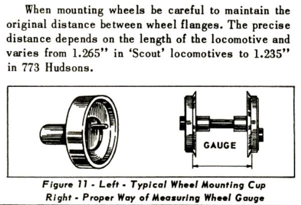
In the past, I have just pressed wheels on, measured ‘around’ 1.25” from flange/tread intersection to flange/tread intersection, and everything ran hunky-dory! I know, Lionel recommends between 1.235” (Hudson) and 1.265 (Scout)”, but I don’t recall ever seeing a chart that shows gauging for each engine – is there one?

Today, remounting some steel tired wheels on a 1666, I ran into a couple of problems – first problem is, where do I measure from on a steel-tired, flanged wheel?  Looking at my not-to-scale, crude drawing below, if I measure from the inner edge of the steel tire to the inner edge of the opposite steel tire, that gives an entirely different measurement than measuring from the projected intersection of the steel tire and flange, about 0.047” difference in total (2 x 0.0235” as shown in drawing.) The "Datum" is my reference of where I NORMALLY measure from on each wheel, that is the intersection of the tread and the flange, a point not available on a wheel with a steel tire.

Second question, same as the first – where do I measure from on a blind, or flangeless wheel?

And lastly, what should the actual measurement be for a set of 1666 wheels? I know this is an old and well-discussed topic, but I have yet to see a chart of gauge measurements for each engine made by Lionel. I'm sure I just missed it 

Wheel Gauging 

George

Attachments

Images (1)
  • Wheel Gauging
Original Post

Replies sorted oldest to newest

The best thing to do, would be to measure a known good runner. 

The 1666 was made many years, both before and after WWII.  It was always considered an O27 loco.  Gauging a loco to run well on O27 track isn't easy.  Too wide and the flanges will tend to bind.  Too narrow, and the wheels may not have enough side-to-side play.

I would try to find one the same vintage as yours (perhaps at York or another big train meet), and make some measurements with a good caliper.

Last edited by Ted S
Somewhere, Lionel says to place an engine in an 0-27 curve; there should be a left to right wiggle, bind; sitting flat. The wheel backside's minimum guage being wide enough to make it past uncoupling magnets, turnout guide rails, etc. can be a bigger concern. More exacting would be measuring from tread meets flange point to backside of opposing wheel.

I think Adriatic has the good advice: empirical testing.

Some of it will depend on where you want to run it. I read an old TCA Quarterly article that pointed out that Lionel originally defined O-gauge as 1 and 3/8", measured from the center of the rails (not 1.25 between the rails, as we typically do now). Because the rails on O-gauge track are larger in diameter than on O-27 gauge track, this means that O gauge is actually narrower than O-27 gauge! This accounts for the gauge on the Scout loco being actually wider than O, since it was designed for O-27. (It also explains why my childhood "Nickel Plate Special" engine won't go gracefully through Ross turnouts!)

I think, once you find out what gauging works, you should measure from your "datum" point, since that approximates the point Lionel measured from on the non-tire-equipped steamers. That way, your finding will be transferable to other engines with the same wheelbase but no tires. Besides, the exact location of the edge of the tire is irrelevant for gauging - it's the flanges that matter.

Once I got the flanged drivers happy, I'd measure the total width of the wheel (outside edge of the left wheel to outside edge of the right wheel) and use that figure to set the blind drivers.


Well gents, that all sounds like good advice. That said, I don't really have the luxury of empirical testing as these are some very old wheels, and more than a few of them (I'm repairing 4 motors) had wheels literally falling off. So I will be regrooving the splines on those axles as best I can and then applying Loctite to insure a solid lock. That Loctite won't leave much time for adjustments assuming I can get the motor on a track and run it through a few curves and switches.

I was hoping to get the Lionel engineering thought process in a well documented manual somewhere, but it doesn't appear to be around, so I will do what I have done in the past. Similar to what Adriatic described, I'll mount the wheels using the projected intersection of the steel tire and the flange, then flip the engine on it's back and take a loose piece of O27 curved track and run the inverted track over the wheels - this gives a pretty good visual and allows me to see the "wiggle room" as well, thus my empirical evidence. Then I'll run the snot out of it fast, slow, forward then backward, routing it thru switches and around the loop, with and without a load. Once I'm happy, I'll do the same for the rest of them.

Thanks ya'll!!!

At one time I tried to measure and record the  gauge on Lionel locos that I was working on. It did not take long to discover that wheel and axle dimensions varied a lot. When installing wheels with wheel cups the end of the axle ends up flush with the face of the hub. This seems to be consistent with the way Lionel installed wheels and everything seems to operate properly when assembled this way.   With the few Lionel engineering drawings I have I worked through the dimensions and found that end of axle flush with face of hub should indeed produce the correct gauge.  I no longer concern myself with checking gauge when I assemble wheels to axles. 

David Johnston posted:

At one time I tried to measure and record the  gauge on Lionel locos that I was working on. It did not take long to discover that wheel and axle dimensions varied a lot. When installing wheels with wheel cups the end of the axle ends up flush with the face of the hub. This seems to be consistent with the way Lionel installed wheels and everything seems to operate properly when assembled this way.   With the few Lionel engineering drawings I have I worked through the dimensions and found that end of axle flush with face of hub should indeed produce the correct gauge.  I no longer concern myself with checking gauge when I assemble wheels to axles. 

Well, that's a VERY interesting approach, and I seem to be headed in that direction too.

Notwithstanding that comment, the 1666 I'm working on now had gear teeth rubbing gear teeth and not just feathering the edges, but raising them into sharp shark tooth-like protuberances on the flat portion of the intermediate reduction gear. Someone else saw that and tried to solve the problem with shims (washers) but actually had them on the wrong side!

So now that it's all back together, I can say it was a delicate balance between 1) rubbing gears, 2) rubbing motor side plates, 3) reducing side-to-side play of each driver set to insure there is at least 60% gear mesh at all times/configurations, and 4) proper width or gauge of the wheels in order not to bind on O27 curves.

Then there are the ones you just put the wheels on and squish 'em with the press - and they turn out just fine!

I would agree that in mounting wheels, getting the gearing right is the most difficult part. This is especially true with the wheels with tires since the are zinc, not steel, and subject to a lot more wear. When pressing steam loco wheels on not only do they have to be quartered properly, the idler gears have to be properly timed so the side rods will go on. Any looseness caused by wear on the shafts or bore on the idler gear or intermediate gear will allow them to cock and rub the wheel or come out of engagement. I try to keep the shaft to bore clearance at 0.002” or less. To do this I have to change a lot of gears and replace the shafts when possible. I use a lot of the 671 thrust washers, 671M-21 (?), to adjust and hold the lateral location of the wheels and gears. 

Add Reply

Post

OGR Publishing, Inc., 1310 Eastside Centre Ct, Suite 6, Mountain Home, AR 72653
800-980-OGRR (6477)
www.ogaugerr.com

×
×
×
×
Link copied to your clipboard.
×
×