


I have several signals operating now and a few more to go. Using both Lionel 183 and MTH ITAD sensors. The Lionel works better as it works with light and dark colored cars like my Broadway Limited set. The MTH ITAD works good with light colored cars and mixed freight consists while it falls short with dark colored cars like my green Jersey Central Madison set. I also use the time tested insulated rail technique and that works great in activating operating units like the switch tower and with signal lights when you add the bridge rectifier and DC SPDT relay.
Tr18
Thanks, for reply back. I will see, if I can mybe make the show.
Thansk, John
Chugman, Please take a look my video on you-tube
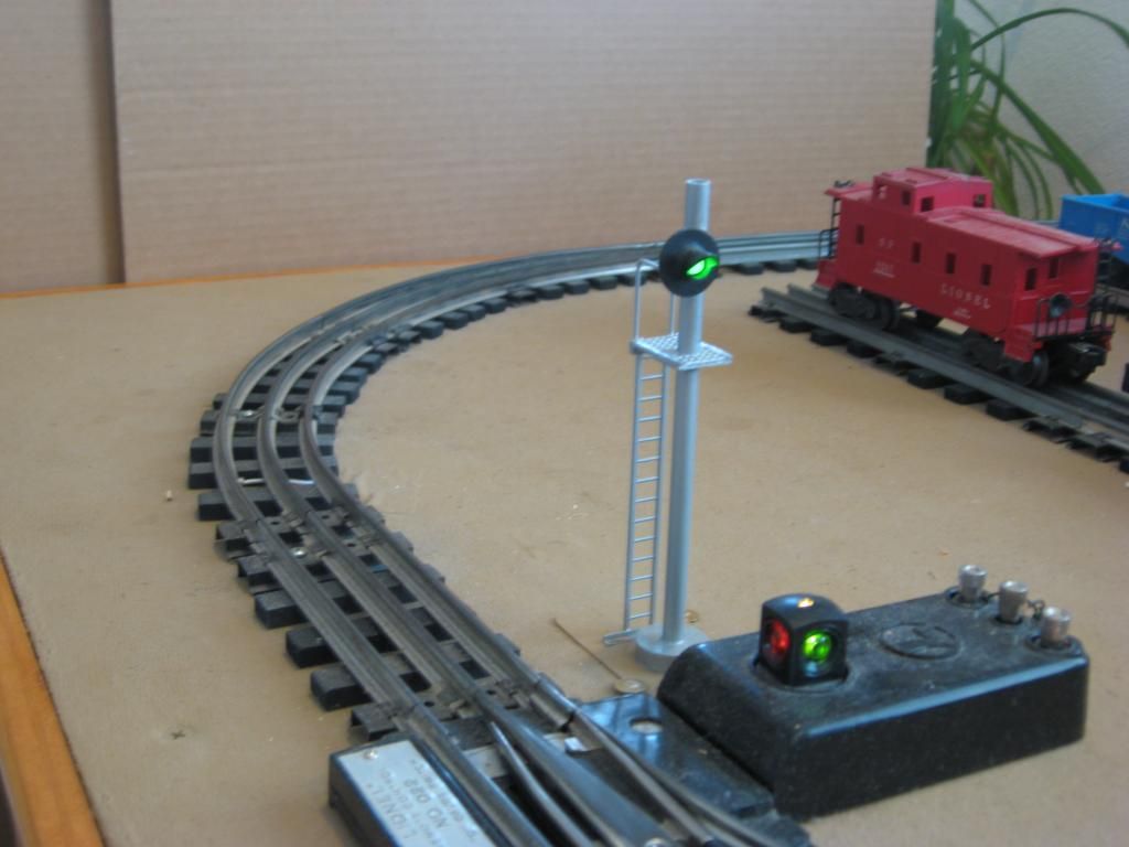
Those are working type Subway Signals
Thanks, John
I have operation signals on my layout.
Lionel # 153 Block Signal wired to a O-22 Switch
Lionel #252 crossing gate and #154 crossing signal. I have these activated by a Relay that is wired to a control rail. I built a flashing circuit for the 154 so the lamps blink left right - left right.
I have a NJ International semaphore. I connected the control rod to a Tortoise Switch machine mounted under the layout. It is manually controlled with a DPDT switch on my control pannel ( an Atlas Twin ). The Semaphore controls traffic out of my yard on to the mainline.
One signal is a MTH Rail King 1 over 1 searchlight. The upper searchlight is wired to a relay and the lower is wired to a O-22 switch.
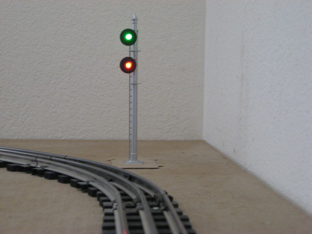
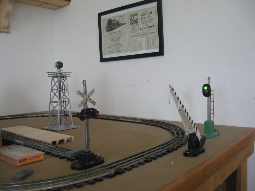
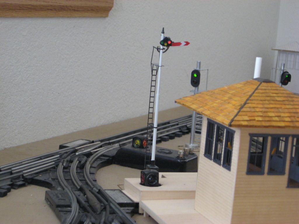
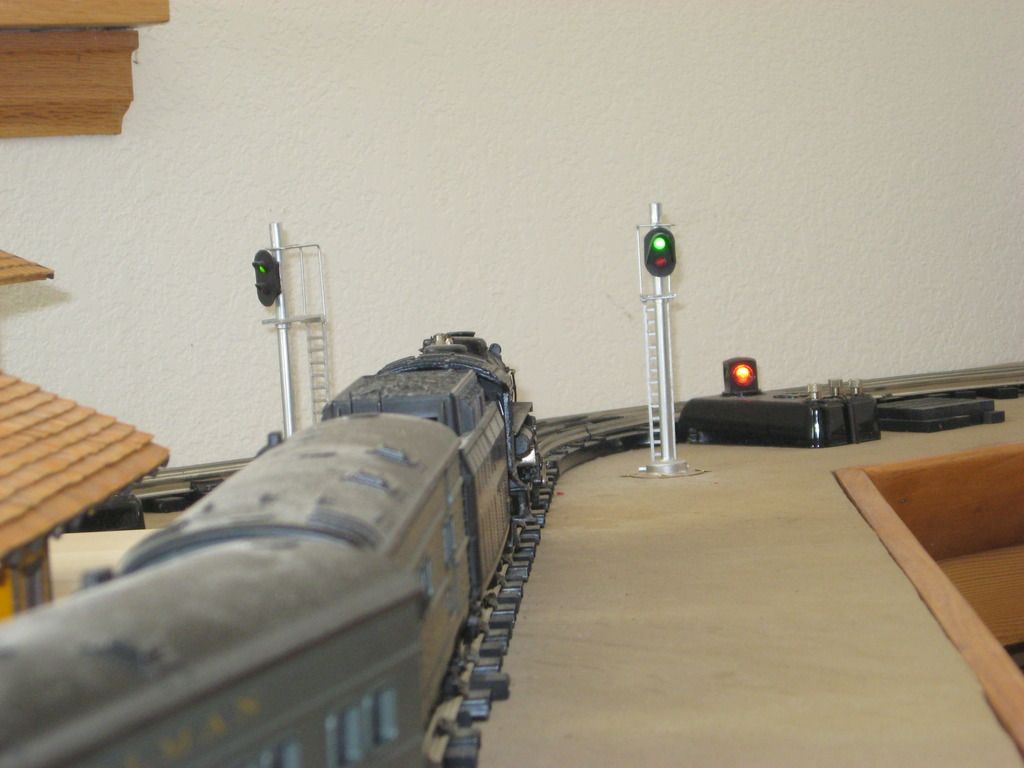
I have mainline signal blocks - Outside control rail and Relays. I have scratch built several signals - Color-Light, Green over Red and Searchlight Signals.
Steve
starting on my signal system with prr signal and interlocking
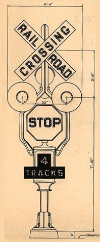
AGHRMatt posted:Mark Preussler makes some signals in O scale and H.O. of an unusual Griswold prototype somewhat unique to the the Midwest (CNW, Soo, etc) but seen as far west as Washington state. The operating ones are expensive because of the hardware, but they're so unique I had to have a pair. I liked them so much I bought two sets -- one early and one late (fixed position stop sign).
Here's a prototype in action at approximately 50 seconds in.
Matt, I've actually visited Bob Rivard's layout. He's a local and a spectacular modeler. He also produces nice videos because it's what he does for a living. He works for a local TV station. I heard recently that the last of the functioning Griswolds was being retired.
Art, I'm not sure if you are still following this topic. Somebody dug it up today. I don't have working signals yet, but they are in the planning stages. I'll be using CMRI and JMRI to control my layout. That combination will allow me to have a rather sophisticated system that will be very prototypical.
I've always been a fan of the searchlight style signal, a single light with mechanical lens system. I'll be using Bruce Chubb's searchlight signal driver cards with CMRI outputs to drive them. Two logic bits can make a bi-color LED yield four aspects, red, green, yellow and dark. There are 12 individual circuits on this card. My wife and I assembled these from components.

This is a kitbashed Lionel 450 signal bridge, modified to span 3 tracks. I scratch built the signals from parts found on eBay.

Attachments
Images (2)
FWIW, over the last year or so there has been a series of articles by Dr. Bruce Chubb on signals in Railroad Model Craftsman magazine. I thought they were very informative, but unfortunately I am missing 3 or 4 issues (not a subscriber) so I don't have the complete set of articles. I do need to see about getting the back issues I am missing. IMO, they should take these articles and make a book from them. I think it would be a good one to have.
Elliot, I imagine you are very familiar with the systems Dr. Chubb has and already know a fair amount about signaling, but these were pretty good articles. Thought you might be interested too, that is if you don't already have them? They were even written so I could understand them, for the most part anyway. ![]()
Big_Boy_4005 posted:AGHRMatt posted:Mark Preussler makes some signals in O scale and H.O. of an unusual Griswold prototype somewhat unique to the the Midwest (CNW, Soo, etc) but seen as far west as Washington state. The operating ones are expensive because of the hardware, but they're so unique I had to have a pair. I liked them so much I bought two sets -- one early and one late (fixed position stop sign).
Here's a prototype in action at approximately 50 seconds in.
Matt, I've actually visited Bob Rivard's layout. He's a local and a spectacular modeler. He also produces nice videos because it's what he does for a living. He works for a local TV station. I heard recently that the last of the functioning Griswolds was being retired.
Art, I'm not sure if you are still following this topic. Somebody dug it up today. I don't have working signals yet, but they are in the planning stages. I'll be using CMRI and JMRI to control my layout. That combination will allow me to have a rather sophisticated system that will be very prototypical.
I've always been a fan of the searchlight style signal, a single light with mechanical lens system. I'll be using Bruce Chubb's searchlight signal driver cards with CMRI outputs to drive them. Two logic bits can make a bi-color LED yield four aspects, red, green, yellow and dark. There are 12 individual circuits on this card. My wife and I assembled these from components.
This is a kitbashed Lionel 450 signal bridge, modified to span 3 tracks. I scratch built the signals from parts found on eBay.
I look at that circuit board and it is greek to me how does someone know how to make something like that like I said greek to me.
My signals are working in that they show the positions of the track switches up ahead. That is more important to me than prototypial operation:

Attachments
Images (1)


AGHRMatt posted:

I look at that circuit board and it is greek to me how does someone know how to make something like that like I said greek to me.
I would love every aspect of model railroading if it wasn't for the wiring and soldering ![]()
**************************
Thats OK Matt I have the same feeling when I look at the well done models and wonder where to start and how and assume modeler have a whole workshop of hobby tools glues jigs infinite sizes of plastics and metal shapes and sheets etc to build. Building models is geek to me also. ![]()


Jhainer posted:I look at that circuit board and it is greek to me how does someone know how to make something like that like I said greek to me.
It's really not that difficult. Just like baking a cake, you follow the recipe. The circuit design was already done, that's what I can't do. However, I am a great copy cat.
In the case of these circuit boards, I bought the printed but unpopulated cards from Chubb, then using the parts list, ordered all the components. That was actually the hardest part, because they came from Digi-key, Jameco and Mouser. After that, follow the instructions, and put the parts in the correct spots. I used to be intimidated by electronics, but I'm getting more comfortable all the time.
If you don't like soldering, a project like this will either cure you or kill you.![]()
BTW, here's a better picture of the fully populated card. Twelve circuits per card.

Attachments
Images (1)
fl9turbo2 posted:Working to install the signal system and signals with computer control system
What Layout Control System are you using? Also what electronics are you using. I recognize the relays, but none of the other circuit boards.
rtr12 posted:FWIW, over the last year or so there has been a series of articles by Dr. Bruce Chubb on signals in Railroad Model Craftsman magazine. I thought they were very informative, but unfortunately I am missing 3 or 4 issues (not a subscriber) so I don't have the complete set of articles. I do need to see about getting the back issues I am missing. IMO, they should take these articles and make a book from them. I think it would be a good one to have.
Elliot, I imagine you are very familiar with the systems Dr. Chubb has and already know a fair amount about signaling, but these were pretty good articles. Thought you might be interested too, that is if you don't already have them? They were even written so I could understand them, for the most part anyway.
I am quite familiar with Chubb's entire system. I haven't been following his RMC articles though. I'm relying heavily on JMRI to take of the software and logic for the signals. From what I have read and watched, it is quite capable of doing this task. I'm guessing this bypasses much of the value of the series.
It doesn't really pay for me to get involved with the new series of articles, because if I'm not mistaken, they are based on Bruce's new hardware, which I won't be using. I have such a glut of his early stuff, which still works, why pay again?
Maybe, I check them out anyway, make sure I'm not missing anything.![]()
rtr12 posted:fl9turbo2 posted:Working to install the signal system and signals with computer control system
What Layout Control System are you using? Also what electronics are you using. I recognize the relays, but none of the other circuit boards.
I am using the original LCS by train American studio the electronics are by azatrax for train detection and relays
I like Terry Christopher's Custom Signals. I am using Atlas O Signals along with them and utilizing Insulated Rail..Next year, when I semi-retire, I plan to wire up accessories, signals, and special lighting effects....It takes a lot of time to wire the Custom Signals, and when you start wiring, have to go to work and then start wiring again, it can get tricky...I really think Signalling like Scenery, Ballast, Buildings, etc., adds a bit of Realism to our Operation Experience. I must admit Bruce Chubb has a neat system, but it's so far Over My Head that I appreciate the Simplicity of The Atlas O, Custom Signal System....This is a great Thread, Happy Railroading....
To all. Have a very Marry Christmas and a Happy New Years to all.
Yes !
Please keep it coming with the Signals up grades.
It's nice to see everyone is adding Signals to their Layouts.
A Layout without Signals isn't a Layout.
Good luck to all, Thanks, John
kb2agpjohn@aol.com
fl9turbo2 posted:rtr12 posted:fl9turbo2 posted:Working to install the signal system and signals with computer control system
What Layout Control System are you using? Also what electronics are you using. I recognize the relays, but none of the other circuit boards.
I am using the original LCS by train American studio the electronics are by azatrax for train detection and relays
Thanks, I need to look into the Azatracks stuff. Many here keep referring to it every so often.
leapinlarry posted:I like Terry Christopher's Custom Signals. I am using Atlas O Signals along with them and utilizing Insulated Rail..Next year, when I semi-retire, I plan to wire up accessories, signals, and special lighting effects....It takes a lot of time to wire the Custom Signals, and when you start wiring, have to go to work and then start wiring again, it can get tricky...I really think Signalling like Scenery, Ballast, Buildings, etc., adds a bit of Realism to our Operation Experience. I must admit Bruce Chubb has a neat system, but it's so far Over My Head that I appreciate the Simplicity of The Atlas O, Custom Signal System....This is a great Thread, Happy Railroading....
The system developed by Dr. Chubb has been around a long time. As I mentioned above, there was a very good series of articles in the Railroad Model Craftsman magazine over the last year or so written by Dr. Bruce Chubb that did a real good job of explaining signal systems. If you happen to have those issues of RMC it's a very good read. Unfortunately, I am missing a few issues in the series.
I also like the Atlas signal system and for anyone interested in it Eric Siegel did a couple of videos on it a few years ago that do a good job of explaining the whole Atlas system. I was pretty well sold on it after watching Eric's videos. So many things to choose from...so little time...I am enjoying all of it.
rtr12 posted:fl9turbo2 posted:rtr12 posted:fl9turbo2 posted:Working to install the signal system and signals with computer control system
What Layout Control System are you using? Also what electronics are you using. I recognize the relays, but none of the other circuit boards.
I am using the original LCS by train American studio the electronics are by azatrax for train detection and relays
Thanks, I need to look into the Azatracks stuff. Many here keep referring to it every so often.
leapinlarry posted:I like Terry Christopher's Custom Signals. I am using Atlas O Signals along with them and utilizing Insulated Rail..Next year, when I semi-retire, I plan to wire up accessories, signals, and special lighting effects....It takes a lot of time to wire the Custom Signals, and when you start wiring, have to go to work and then start wiring again, it can get tricky...I really think Signalling like Scenery, Ballast, Buildings, etc., adds a bit of Realism to our Operation Experience. I must admit Bruce Chubb has a neat system, but it's so far Over My Head that I appreciate the Simplicity of The Atlas O, Custom Signal System....This is a great Thread, Happy Railroading....
The system developed by Dr. Chubb has been around a long time. As I mentioned above, there was a very good series of articles in the Railroad Model Craftsman magazine over the last year or so written by Dr. Bruce Chubb that did a real good job of explaining signal systems. If you happen to have those issues of RMC it's a very good read. Unfortunately, I am missing a few issues in the series.
I also like the Atlas signal system and for anyone interested in it Eric Siegel did a couple of videos on it a few years ago that do a good job of explaining the whole Atlas system. I was pretty well sold on it after watching Eric's videos. So many things to choose from...so little time...I am enjoying all of it.
I could not use the atlas system because I wanted a true prototypical B&O system I have every type of color position signal they made and now I had NJ international build me prototypical B&O dwarf signals in every color they had, All of the different system are good it's a aspect of model railroading that people don't take much time with, For me from the start I want a working prototypical system and since I grew up in Baltimore Maryland that's what I did. But it take a lot of work and time to find someone who will work with you to make it happen
what's good about the azatrax system is it works with every signal made today
That's good to know about Azatrax too. As for the signals, I really don't know how they all are supposed to work. The RMC articles do a pretty good job of explaining that too, FWIW. I don't know that they are specific to any one RR, but they give a general idea. Sounds like you have a good understanding of their operation already though.
rtr12 posted:That's good to know about Azatrax too. As for the signals, I really don't know how they all are supposed to work. The RMC articles do a pretty good job of explaining that too, FWIW. I don't know that they are specific to any one RR, but they give a general idea. Sounds like you have a good understanding of their operation already though.
for me to get a prototypical system going I had to do some reading of the rule book so I had to know what type of signal goes with what area on the layout, But if you are looking to do it you may want to develop your own rules and Taylor your signals the way you want them to act on your layout. There is no right or wrong way its all on what you want to get out of them, They can be just for show or they can be as realistic as you want them
I am pretty prototypically challenged, so RR specific with different signals for different areas is probably not for me. Just getting some and operating them with block detectors would be fine for me, red, yellow, green or maybe even just red and green.
I was very impressed by the Atlas signal system after watching Eric Siegel's videos and I was all set for those until Atlas had all the problems with their manufacturing. I still don't know if they are available again? They seemed to have it all covered and it looked to be fairly easy to get up and running as it did all the logic if you got it wired and set up correctly.
I also like the Azatrax stuff and am still looking at that. I like the electronics part of the hobby. Also several others here have mentioned the Azatrax items when talking about signals so they must be pretty good and also pretty popular. I have a lot to learn though and old dogs are slow at learning new tricks. ![]()
Then gunrunnerjohn has posted a circuit schematic for block detection that I saved. The build your own boards method sounds interesting too. Doing an entire system like that may be a little over my head though? ![]()
I just installed my first Atlas Type G signal today. I have to complement Eric Siegel for his youtube video. After watching it, he sure explained how simple the install is for these. He certainly clarified the Atlas instructions which were intimidating. I have 10 blocks on my 16'x35' pike. I will be installing and integrating 20 to cover travel in both directions eventually. Right now I am putting 8 in to allow me to get to some ballasting and scenery detailing on one portion of the layout. Chugman, you speak about the cost. You have a big layout, but the cost is the equivalent of a couple diesels or a legacy steamer. I think its a must to really add to that fantastic layout of yours. I do not believe you will regret it.
I have a number of the Atlas 'G' type as well. One of the things I realized after the fact was viewing angle to see the signals. If I ended up installing them like I thought I wanted, viewers would not have been able to see some of them. I opted to forget about prototypical operation in favor of aesthetics. But I really think they are the icing on the cake! I used to really admire the display Terry Christopher had at York. If I had known he was retiring from it, I would have stocked up. Does anyone know if Atlas still produces these anymore?
NYC z-man. Contact Terry directly. I don't think he is totally out of it yet.
The Atlas O website is showing several of their signals as 'In Stock'. I guess they have replenished some of the supply. I didn't see their dwarf signals, but they had a few others including the 4 packs.
Yeah I do, They run off either track and those tracks run off a CW-80 and a ZW. They are powered off the CW-80 accessory power, not track power.
Send me a PM if you need to know more on how to do it.
I have four of the G Type signals installed and 16 more to go. They work independent of each other, but when I connected them to run them integrated they are not working correctly. The first three signals stay red. I do not see a continuity issue between isolated blocks because they are working correctly in stand alone operation.
I am using 6 pin phone cords my brother provided because he was in the phone business. Are these cords functional with the system? Is there a difference in these cords and the ones made for the system by Atlas?
I have them connected as follows: Signal 1 J2 is open, Signal 1 J1 to Signal 2 J2, Signal 2 J1 to Signal 3 J2, Signal 3 J1 to Signal 4 J2, Signal 4 J1 is open. I did it just like Eric Seigel demonstrated on his video.
I start trouble shooting tomorrow. Any input on the connecting cords would be welcome and help rule out at least one issue. Here I thought it would be easier than this based on Eric's explanatory video. The under layout wiring and all the turnouts make it a little more confusing than the 6 foot demonstration, but I am hoping it is just a foolish mistake I made rather than a problem with the signals.
Bob,
What I did with my Atlas Signal I used the Phone type wall Receptacles under the Signal head and then run my phone wires back to Relay Panel board.
l hope that may clear up some wiring problems.
Bob, you can use Phone Wires Plugs, also but you may have to play around with it because it's a little smaller in size when you plug it in to the Phone Receptacles.
Be careful you don't short it out. You don't want to burn out your Led's in the Signal head.
Please keep us posted on your wiring progress here.
Good luck, John kb2agpjohn@aol.com
Boo Man posted:I have four of the G Type signals installed and 16 more to go. They work independent of each other, but when I connected them to run them integrated they are not working correctly. The first three signals stay red. I do not see a continuity issue between isolated blocks because they are working correctly in stand alone operation.
I assume these are all "intermediate block signals" all in one direction?
No turnouts involved?
I am using 6 pin phone cords my brother provided because he was in the phone business. Are these cords functional with the system? Is there a difference in these cords and the ones made for the system by Atlas?
are the 6 pin phone cords pre-made with connectors already attached or are you crimping your own connectors on?
you need to be sure both ends of the wire are done the same way. Did the signals come with short 6" pre-made jumper wires? Have you tested using those?
I have them connected as follows: Signal 1 J2 is open, Signal 1 J1 to Signal 2 J2, Signal 2 J1 to Signal 3 J2, Signal 3 J1 to Signal 4 J2, Signal 4 J1 is open. I did it just like Eric Seigel demonstrated on his video.
This appears to be correct.
I start trouble shooting tomorrow. Any input on the connecting cords would be welcome and help rule out at least one issue. Here I thought it would be easier than this based on Eric's explanatory video. The under layout wiring and all the turnouts make it a little more confusing than the 6 foot demonstration, but I am hoping it is just a foolish mistake I made rather than a problem with the signals.
Take a look at this attachment and see if the wires you are using conform to these requirements. The actual colors are not important, just that the color orientation is the same at both ends.
Attachments
Files (1)
tr18 posted:Boo Man posted:I have four of the G Type signals installed and 16 more to go. They work independent of each other, but when I connected them to run them integrated they are not working correctly. The first three signals stay red. I do not see a continuity issue between isolated blocks because they are working correctly in stand alone operation.
I assume these are all "intermediate block signals" all in one direction?
Yes, they are all in one direction.
No turnouts involved?
The first block has 3 turnouts, the second block has 2 turnouts, the third block has 0 turnouts, and the fourth block has 2 turnouts. I have all turnouts isolated on both sides. I have a bus wire underneath each block that has feeders for continuity. The blocks are 16-18 feet in length. No feeders are attached in the areas isolated for the turnouts.
I am using 6 pin phone cords my brother provided because he was in the phone business. Are these cords functional with the system? Is there a difference in these cords and the ones made for the system by Atlas?
are the 6 pin phone cords pre-made with connectors already attached or are you crimping your own connectors on?
The phone cords are RCA brand pre-made.
you need to be sure both ends of the wire are done the same way. Did the signals come with short 6" pre-made jumper wires? Have you tested using those?
Not sure what you are saying here. The signals are pre-wired with a 8-9" cords that connect to the board via a clip type connector. Per my bro, the Atlas connector for the signal is RJ45 (larger clip) and the female J1 and J2's on the board are for RJ11's (smaller clip).
I have them connected as follows: Signal 1 J2 is open, Signal 1 J1 to Signal 2 J2, Signal 2 J1 to Signal 3 J2, Signal 3 J1 to Signal 4 J2, Signal 4 J1 is open. I did it just like Eric Seigel demonstrated on his video.
This appears to be correct.
I start trouble shooting tomorrow. Any input on the connecting cords would be welcome and help rule out at least one issue. Here I thought it would be easier than this based on Eric's explanatory video. The under layout wiring and all the turnouts make it a little more confusing than the 6 foot demonstration, but I am hoping it is just a foolish mistake I made rather than a problem with the signals.
Take a look at this attachment and see if the wires you are using conform to these requirements. The actual colors are not important, just that the color orientation is the same at both ends.
I reviewed the attachment. I am providing a photo (blurry, but macro photography isn't my phone's specialty, but the wire colors are visible) of the two clips on both ends of phone cord. As you can see side by side the colors mirror themselves which mean the wires run straight through the cord.
Does someone have the Atlas or Custom signal connecting cords? Can someone photograph both ends side by side like this so we can compare them?
If I am understanding the attachment correctly, I believe Atlas/Custom signals cords side by side would be black/red/green/yellow and black/red/green/yellow rather than the mirror image below for the phone cord - black/red/green/yellow and yellow/green/red/black.
If this is correct, the phone cords as manufactured are my problem. The solution would then be either buy the Atlas/Custom Signals cords or buy a crimper and reverse the clip on one end of the phone cords.
I hope someone can provide photos of the Atlas cord. I'd also welcome thoughts on the potential solutions. I'd hate to reverse one clip and ruin two G type signals I can no longer purchase. Another question is can I readily purchase the cords from Atlas?

Attachments
Images (1)

Boo Man posted:tr18 posted:Boo Man posted:I have four of the G Type signals installed and 16 more to go. They work independent of each other, but when I connected them to run them integrated they are not working correctly. The first three signals stay red. I do not see a continuity issue between isolated blocks because they are working correctly in stand alone operation.
I assume these are all "intermediate block signals" all in one direction?
Yes, they are all in one direction.
No turnouts involved?
The first block has 3 turnouts, the second block has 2 turnouts, the third block has 0 turnouts, and the fourth block has 2 turnouts. I have all turnouts isolated on both sides. I have a bus wire underneath each block that has feeders for continuity. The blocks are 16-18 feet in length. No feeders are attached in the areas isolated for the turnouts.
I am using 6 pin phone cords my brother provided because he was in the phone business. Are these cords functional with the system? Is there a difference in these cords and the ones made for the system by Atlas?
are the 6 pin phone cords pre-made with connectors already attached or are you crimping your own connectors on?
The phone cords are RCA brand pre-made.
you need to be sure both ends of the wire are done the same way. Did the signals come with short 6" pre-made jumper wires? Have you tested using those?
Not sure what you are saying here. The signals are pre-wired with a 8-9" cords that connect to the board via a clip type connector. Per my bro, the Atlas connector for the signal is RJ45 (larger clip) and the female J1 and J2's on the board are for RJ11's (smaller clip).
I have them connected as follows: Signal 1 J2 is open, Signal 1 J1 to Signal 2 J2, Signal 2 J1 to Signal 3 J2, Signal 3 J1 to Signal 4 J2, Signal 4 J1 is open. I did it just like Eric Seigel demonstrated on his video.
This appears to be correct.
I start trouble shooting tomorrow. Any input on the connecting cords would be welcome and help rule out at least one issue. Here I thought it would be easier than this based on Eric's explanatory video. The under layout wiring and all the turnouts make it a little more confusing than the 6 foot demonstration, but I am hoping it is just a foolish mistake I made rather than a problem with the signals.
Take a look at this attachment and see if the wires you are using conform to these requirements. The actual colors are not important, just that the color orientation is the same at both ends.
I reviewed the attachment. I am providing a photo (blurry, but macro photography isn't my phone's specialty, but the wire colors are visible) of the two clips on both ends of phone cord. As you can see side by side the colors mirror themselves which mean the wires run straight through the cord.
Does someone have the Atlas or Custom signal connecting cords? Can someone photograph both ends side by side like this so we can compare them?
If I am understanding the attachment correctly, I believe Atlas/Custom signals cords side by side would be black/red/green/yellow and black/red/green/yellow rather than the mirror image below for the phone cord - black/red/green/yellow and yellow/green/red/black.
If this is correct, the phone cords as manufactured are my problem. The solution would then be either buy the Atlas/Custom Signals cords or buy a crimper and reverse the clip on one end of the phone cords.
I hope someone can provide photos of the Atlas cord. I'd also welcome thoughts on the potential solutions. I'd hate to reverse one clip and ruin two G type signals I can no longer purchase.
Bob
Those wires won't work. When put side by side the colors need to be in the same sequence and not a mirror image. I can send you a pic if you like but not until next week since all our stuff is at the club. Since you already have the wires, I think the easiest solution for you would be to cut off one connector and re-crimp a new one in the correct orientation.
Now that I recall, I don't believe the Atlas signals came with a pre-made jumper wire. The majority of our signals came from Custom Signals and many of his came with the pre-made 6" jumper wire. We used those wherever the circuit boards were close enough and crimped our own wires where we needed a longer jumper. For the rest we bought a six conductor flat wire and are crimping the RJ11's as we go.
This stuff can drive you nuts!!!![]()
![]()
![]()


Attachments
Images (2)
John and John (TR18)
Thanks for the input. No need to waste any time troubleshooting thanks to your prompt feedback. I bought all these phone cords 4 years ago then have been on hiatus from the layout due to life's issues with aging parents. However, I am back with a zeal and can't wait to move forward. I owe you guys a beer. Glad that the money spent on all those cords won't be wasted. I will get a crimper.
John (TR18),
That is one intimidating picture with all those signal boards. I just bookmarked your website. I love watching train vids and will have to watch all of yours. That is one hell of a layout.
Since visuals are worth a million words and for documentation sake, please put up a photo when you have a chance. It will assist those who reference this in the future. Thanks to you and Eric Siegel, what appeared intimidating at first now seems achievable with less effort than expected.
All,
I will report back when I am crimped and have all my signals wired up.
Thanks a ton,
Bob
Long ago, when the modular cord concept was developed, a decision was made by the Bell System to manufacture single-line telephone cords such that the modular plug reversed the polarity of the two pairs of wire in the cord. The decision was not actually to create a reversal, but it was a manufacturing expedient. The bulk cordage has a ridge molded into the outer sheath, and the ability by workers, and subsequently by machines, to identify that ridge, allows the plugs to be installed uniformly. Because the cordage is flat, rather than round (as used in cords with a higher pair count) the reversal occurs.
Many industries now use modular cords in their interconnection schemes. Non phone-related products such as home automation, alarms, HVAC, and now toy train systems, use these ubiquitous cords due to the ease of interconnection, and their ready availability.
You have discovered the pitfalls of trying to use a product from one industry, (where, in this case, the idiosyncrasy of a built-in reversal is mitigated by other telephone industry interconnecting devices) is used by other industries, without the designers actually understanding (or effectively communicating to customers) the underlying design and potential frustrating problems that can be created.
Even those of us in the phone industry constantly need to educate and correct new workers in this particular weirdness. You wouldn't imagine the number of times we have been called to a premises where a DIY customer has fouled up his service over such a seemingly trivial issue.
Here's a quick note for folks interested in learning something new, and wishing to acquaint themselves with the real nomenclature : The small plugs are called "6P4C" (six position, four contact) not "RJ-11". The big ones for data service are called 8P8C , not "RJ45". The real small plugs, used on telephone handset cords, are not RJ-12, or RJ anything. They are 4P4C. The JACKS (female connections) are the only thing "allowed" by the FCC to be referred to as "RJ" which stands for "Registered Jack". Unless a jack is wired to, and providing service from, the PSTN (Public Switched Telephone Network) it is not a "registered jack" and is not called RJ-anything. A subtle point, but to professionals in my industry, it's akin to fingernails on the blackboard syndrome. Sorta like the way the terms "lashup" or "RDC cars" are to us RR modelers.
I used the jumper cable as a guide for how to insert wire colors at each connector end just to keep everything standard. Also helped that I had a cable tester that verified all crimps were OK and in correct order. Cable tester had two jacks for cable ends. Unit sent power down one wire at time which lit an led on front. If leds lit in consecutive order, then cable was OK. If one led didn't light or two lit at once then cable crimp(s) were bad. Sometime just repressing plug in crimper did the trick, other times, cut off plug and redo new one.
I ordered my crimping tool and rj11 6p/4c modular plugs to complete the job. Thanks again TR18.
An update...I have 12 of 20 signals installed, but am still awaiting my crimping tool from Amazon to attempt the integrated connections between boards.
In the interim in stand alone mode, the signals are cool to watch in action. They really add to the layout and will really add to the realism of running trains. I have 3 passing sidings that will receive quite a bit of action while running trains in both directions. For switching off the main, the signals will come in very handy for multiple operators.
My layout is 16x35 and has 20 turnouts on the single mainline. I have a bus wire that I ran all the way around the layout for continuity. I cut it at each block. After isolating the switches by cutting rails, I had to drop additional feeders to maintain continuity within each block. Once you work with the signals like I have, they really aren't as intimidating as they were before I watched Eric's video. For the umpteenth time, thanks for the video Eric.
Hi Art, Wow, this post has really grown and I plan to sit back and start at the beginning and study in detail the different thoughts concerning signaling...This is awesome and I know that I like the Atlas O system only because its easy...I do not like complicated as I have a simple mind and I am fond of the KISS System..... Thank you for asking this question...Your layout is really Super Nice......
Add Reply
Sign In To Reply
