
While building my layout I decided to use Custom Signals. They are a great product and it is amazing how they work together. Anyways, The owner said there was no easy way to wire the Fastrack turnouts so that the signals can detect direction. It needs only one wire. Has anyone used Custom Signals or something similar? How did you connect the wire to the turnout?

Original Post

Replies sorted oldest to newest

Unfortunately the instructions are complicated and the owner has no specific solution for FasTrack. He sent me two solutions.
 
This is what he said:
 
Michael,
 
Unfortunately, there is no simple solution to the FastTrak connection.  I have spoken to the execs at Lionel about a simple solution, but they have not moved forward on it.  I have done some previous installations with success.  I will go over 2 solutions with you.
 
1. A simple connection of a very small gauge wire to the outside point on the switch will give you a ground when the turnout goes to the diverting route.  This is a simple solution, but not 100% effective.  See photo 3821
 
2. another more difficult solution, but more reliable is to work inside the turnout.  If you glue a wire to the throw bar in just the right position, it will ground out as the turnout goes to the diverting route.  The copper strap inside the switch is attached to common.  As the wire slides over the strap, it grounds out.  See photos 3830.
 
If you can come up with a better idea, please let me know.  I have not investigated the electronics in the switch to offer any solution there.
 
Terry  
 
 
Originally Posted by gunrunnerjohn:

Do you have a link to the instructions for this signal?

DSCN3821

DSCN3830

Attachments

Images (2)
  • DSCN3821
  • DSCN3830
I found this article and think I can modify it so that it solves my problem. 


Originally Posted by ADCX Rob:

If the controller can detect position, the signal can be made too also. 


The trick would be to reverse engineer the controller and it's indicator light circuit.  If it is like K-Line's, there is some diode logic, that should be about it.

Originally Posted by gunrunnerjohn:

I'd take the suggestion about using the microswitch for block power control with a grain of salt!  I doubt you'd want to run a lot of power through those switches.   OTOH, for controlling signals, that seems like a good idea.

coarse I'm using under the table switch machines but if you could mount a micro switch at the throw bar you could use it to ground out the wire for the signals.
It wouldn't  have to carry any track load . That's the way my MTH signals are wired under my layout now . The light is green hit the button to activate the switch switch points move and hit the micro switch under the table light turns to red.

You could do the same thing only running your ground thru the micro switch instead of a hot wire.
Although you can go to a electrical supply that sells Allen-Bradley and get a micro switch that will more than carry the track load. It won't be one of those cheap little 50 cent plastic things though.

I think that doing the way that the manufacture suggests is asking for it. I would try all I could NOT to ground those switch points . They're insulated for a reason. When the rollers brush them they don't spark and now your going to have them grounded?
bad idea. If you can attach a wire to the throw bar and have it extend over to where the switch stand would be that would allow you to use the micro switch.

David

Last edited by Former Member

You do not need to open up the the Fastrack switch to accomplish what you want. I have connected these Solid State relays to the Yellow/Black signal wires. This relay will trip on 5V DC with no problem. You can hook up two of them to each turnout if you wish, reversing the polarity for the two relays.


I may not have exactly the right one listed here but there are loads of these on eBay that you can check out.


http://www.ebay.com/itm/New-So...;hash=item3cc18e47ba


Denny

David, I'm just saying don't try to use the little microswitches in the switch for block power control, which is what seems to be implied by the tutorial we were looking at.


I agree about not grounding the switch points that are currently not grounded, I've had a couple of issues with locomotives going over the switches and shorting without those being also grounded.

Originally Posted by Denny Lyons:

You do not need to open up the the Fastrack switch to accomplish what you want. I have connected these Solid State relays to the Yellow/Black signal wires. This relay will trip on 5V DC with no problem. You can hook up two of them to each turnout if you wish, reversing the polarity for the two relays.


I may not have exactly the right one listed here but there are loads of these on eBay that you can check out.


http://www.ebay.com/itm/New-So...;hash=item3cc18e47ba


Denny

Those you linked appear to specify 24 VAC as a minimum switched voltage.  Don't know what it would do with lower voltages, but you might want one that specifies lower voltages.

Hello John,


All of them specified that voltage. But, I bought a few of them last year, tried them out with lower voltages, and put them away for future projects. I am in Germany now and won't return for another 10 days. I will try it out again and report how they work trying 12V AC.


I know that I was satisfied with the earlier results as I planned on having them control a signal man. In fact I ordered another batch of them for future use. I believe that I have a dozen of them.


If they don't work for lower voltage I will have the Fastrack switch direction control them to turn on my whole house air conditioner, my electric range, my heating system, and my dishwasher.


Cheers

Denny

Originally Posted by gunrunnerjohn:

David, I'm just saying don't try to use the little microswitches in the switch for block power control, which is what seems to be implied by the tutorial we were looking at.


I agree about not grounding the switch points that are currently not grounded, I've had a couple of issues with locomotives going over the switches and shorting without those being also grounded.

John I agree with you 100 percent the little switches are not heavy enough to run trains off of. They should always be used with a relay of some sort . His best bet is to fashion a mechanical arm of some kind that moves with the switch points to move a micro switch attached to a relay .

Makes me glad I'm using Ross switches.

David

Originally Posted by Denny Lyons:
If they don't work for lower voltage I will have the Fastrack switch direction control them to turn on my whole house air conditioner, my electric range, my heating system, and my dishwasher.

Well, that's one way to handle it!


BTW John,


I followed that tutorial and modified one of my switches to control the watchman. It worked fine for about two weeks and then the switch stopped working. I now use it for spare parts. It was after that that I tried out these relays.

Yep, I wonder about those switches and the logic internally.  I think I'll just connect switch controllers to them.

David, You do not need to juryrig a mechanical approach. The Fastrack switch has

4 wires, Red, Green, and Black for momentary switching and the Yellow/Black pairing for a constant 5V positive or negative DC output for LED indicators. The yellow and black wire taps are available externally on the switch and can be used for 5V DC relay control. These taps are the ones that the remote controller is hooked to. This is a piece of cake.

There are plenty of 5V DC relay options ranging from the ones that I showed in the earlier post down to pcb micro relays. I have tried a number of them and they all work.

Cheers

Denny

Originally Posted by Denny Lyons:

David, You do not need to juryrig a mechanical approach. The Fastrack switch has

4 wires, Red, Green, and Black for momentary switching and the Yellow/Black pairing for a constant 5V positive or negative DC output for LED indicators. The yellow and black wire taps are available externally on the switch and can be used for 5V DC relay control. These taps are the ones that the remote controller is hooked to. This is a piece of cake.

There are plenty of 5V DC relay options ranging from the ones that I showed in the earlier post down to pcb micro relays. I have tried a number of them and they all work.

Cheers

Denny

Denny,


So could I use this wire for the led indicator on the switch for my signals? I have to run a wire from the switch to the turnout indication circuit board so that it can tell when the turnout is switched to the curve.

David,

What has that got to do with answering the question on hand? Please use your knowledge of Ross and help Lee 145 with his problem.


Djsixpack,

Can I assume that your name is Michael?


Look at the connection from your controller to the switch. There are 4 wires. Remove those wires from the switch. You will now have 4 terminals available on the switch from where you removed the wires. Take a short length of wire and momentarily make contact between the Red (out) terminal and the Black (common) terminal. This will throw the switch to out (curve) position. Momentarily touching Green (thru) to Black will throw the switch to thru (straight). I suggest that you remove the controller wire from the switch and get the hang of what is  happening. Short the black terminal to the red terminal and watch the track turn to out. Short the  black to the green terminal and watch the track change to to thru. The black wire is common.


Now if you have a volt/ohm multi-tester set it to DC voltage and measure the voltage that is available between black and yellow. When the turnout is out, you should see -5 V DC. When the switch is set to thru you should see +5 V DC. This voltage is constant and will stay in that state until you throw the switch again.

Now you are ready to connect the controller again. But, this time add two additional wires, one to the black terminal and the other to the yellow terminal. These two wires will help you determine the direction of the switch. If these two wire are connected to 5V DC relay you can control whatever you have connected to the relay. Reversing those two wires will activate your relay when the switch is in the opposite direction. You could even control two relays, one connected with one polarity and the other with the opposite polarity.


Your question is more loaded than my explanation. I don't know your signals circuitry but I would be surprised if you could control the signals directly from these two wires. That is the purpose of the relays. It allows you to control your signals based on what is flowing through the relay.


Keep the questions coming. Lots of folks learn from this.

Cheers

Denny


Last edited by Denny Lyons
Denny,
 
Yes, my name is Michael. I attached a PDF of how the circuit boards for turnout indication should be set up as per Custom Signals. The terminal strip where the orange wires are going will connect with the corresponding turnout. I know thing are vague but Terry cannot get any good response from Lionel. 
 
 
Originally Posted by Denny Lyons:

David,

What has that got to do with answering the question on hand? Please use your knowledge of Ross and help Lee 145 with his problem.


Djsixpack,

Can I assume that your name is Michael?


Look at the connection from your controller to the switch. There are 4 wires. Remove those wires from the switch. You will now have 4 terminals available on the switch from where you removed the wires. Take a short length of wire and momentarily make contact between the Red (out) terminal and the Black (common) terminal. This will throw the switch to out (curve) position. Momentarily touching Green (thru) to Black will throw the switch to thru (straight). I suggest that you remove the controller wire from the switch and get the hang of what is  happening. Short the black terminal to the red terminal and watch the track turn to out. Short the  black to the green terminal and watch the track change to to thru. The black wire is common.


Now if you have a volt/ohm multi-tester set it to DC voltage and measure the voltage that is available between black and yellow. When the turnout is out, you should see -5 V DC. When the switch is set to thru you should see +5 V DC. This voltage is constant and will stay in that state until you throw the switch again.

Now you are ready to connect the controller again. But, this time add two additional wires, one to the black terminal and the other to the yellow terminal. These two wires will help you determine the direction of the switch. If these two wire are connected to 5V DC relay you can control whatever you have connected to the relay. Reversing those two wires will activate your relay when the switch is in the opposite direction. You could even control two relays, one connected with one polarity and the other with the opposite polarity.


Your question is more loaded than my explanation. I don't know your signals circuitry but I would be surprised if you could control the signals directly from these two wires. That is the purpose of the relays. It allows you to control your signals based on what is flowing through the relay.


Keep the questions coming. Lots of folks learn from this.

Cheers

Denny


Attachments

Michael, and everyone else
The Custom Signals TSC(Turnout Switch Controller) is looking

for a GND not 5Volts. I use Custom Signals with Ross/Atlas switches.

The Ross switch operates with a DZ1000 motor and a DZ1008 relay

for providing a "system" GND to the TSC. I can see why Terry

suggested a wire connected to the "point" rail to pick-up a GND
when that rail contacts the outside rail. That would trigger the TSC

and cause your lights to indicate a switch in the turn-out position.

The idea of a 5V relay controlled by the Fasttrack switch motor makes

sense to me also. Kinda like I'm using the DZ1008 relay with the DZ1000

switch motor. The switch motor operates the relay and the relay sends

the GND to the TSC.  Denny's idea is similar to my setup. He is applying

it to a Fastrack switch using different equipment, but the principle is

the same. If the Fastrack switch could put out a GND when in the
turn-out position you wouldn't need the relay.
"I feel your pain"
Good luck
Joe

ps: Just looked at the picture on the CCT site and the Fastrack motor is

somewhat similar to the DZ1000 in operation. The DZ1000 has one less

micro switch. But both use a micro motor and gear to throw the switch.

Last edited by JoeTheBro
Joe,
 
Thank you for the info. How do you like your signals by the way? Do you have photos, youtube video, or a website showing your layout? It seems like there would be an easier way to connect this together.
 
Michael
 
Originally Posted by JoeTheBro:

Michael, and everyone else
The Custom Signals TSC(Turnout Switch Controller) is looking

for a GND not 5Volts. I use Custom Signals with Ross/Atlas switches.

The Ross switch operates with a DZ1000 motor and a DZ1008 relay

for providing a "system" GND to the TSC. I can see why Terry

suggested a wire connected to the "point" rail to pick-up a GND
when that rail contacts the outside rail. That would trigger the TSC

and cause your lights to indicate a switch in the turn-out position.

The idea of a 5V relay controlled by the Fasttrack switch motor makes

sense to me also. Kinda like I'm using the DZ1008 relay with the DZ1000

switch motor. The switch motor operates the relay and the relay sends

the GND to the TSC.  Denny's idea is similar to my setup. He is applying

it to a Fastrack switch using different equipment, but the principle is

the same. If the Fastrack switch could put out a GND when in the
turn-out position you wouldn't need the relay.
"I feel your pain"
Good luck
Joe

ps: Just looked at the picture on the CCT site and the Fastrack motor is

somewhat similar to the DZ1000 in operation. The DZ1000 has one less

micro switch. But both use a micro motor and gear to throw the switch.

Originally Posted by Denny Lyons:

David,

What has that got to do with answering the question on hand? Please use your knowledge of Ross and help Lee 145 with his problem.


Djsixpack,

Can I assume that your name is Michael?


Look at the connection from your controller to the switch. There are 4 wires. Remove those wires from the switch. You will now have 4 terminals available on the switch from where you removed the wires. Take a short length of wire and momentarily make contact between the Red (out) terminal and the Black (common) terminal. This will throw the switch to out (curve) position. Momentarily touching Green (thru) to Black will throw the switch to thru (straight). I suggest that you remove the controller wire from the switch and get the hang of what is  happening. Short the black terminal to the red terminal and watch the track turn to out. Short the  black to the green terminal and watch the track change to to thru. The black wire is common.


Now if you have a volt/ohm multi-tester set it to DC voltage and measure the voltage that is available between black and yellow. When the turnout is out, you should see -5 V DC. When the switch is set to thru you should see +5 V DC. This voltage is constant and will stay in that state until you throw the switch again.

Now you are ready to connect the controller again. But, this time add two additional wires, one to the black terminal and the other to the yellow terminal. These two wires will help you determine the direction of the switch. If these two wire are connected to 5V DC relay you can control whatever you have connected to the relay. Reversing those two wires will activate your relay when the switch is in the opposite direction. You could even control two relays, one connected with one polarity and the other with the opposite polarity.


Your question is more loaded than my explanation. I don't know your signals circuitry but I would be surprised if you could control the signals directly from these two wires. That is the purpose of the relays. It allows you to control your signals based on what is flowing through the relay.


Keep the questions coming. Lots of folks learn from this.

Cheers

Denny


You know Denny it's guys like you that get on here and act like your the one running the show here? If you spent as much time reading others post's here as you do berating others  you'd have seen in one of my first post's to this thread exactly how I wire Ross switches for signals . Simple - Single pole double throw normally open normally closed micro switch activated by the operating lever of the switch machine.
Now you figure it out.
David

I don't mind helping anyone on this forum or any other. I've said time and again if they want to they can email me directly. I will always take the time to answer any question I can . Now with that said maybe there's a different way they ask for help in the big cities these days,maybe I've missed something.
But if that's the way it's done ,save yourself some time and don't bother asking me.

Last edited by Former Member

Hello David,


I had to re-read my post to see what I had posted that would ellicit such a strong comeback by you. I intended to reply "tongue in cheek" to your "tongue in cheek" reply. I meant it in good humor. But, when I finished re-reading it became clear that I

was much more terse than I intended. I am sorry that I offended you or any other reader. That is not my style.


Cheers

Denny

Hello Michael,


There are a number of 5V PCB relay modules on eBay. I am sure that you can get them from Digikey and Mouser also. You can create leads from the pins on the relay by connecting Male/Female breadboard jumper wires. The power for the relay comes from the yellow and black leads that we described earlier. You can then connect pole to common on your track layout (that is providing the ground that is identified by Joe) and then connect the orange from your signal to the throw pin. I don't have the parts in front of me as I am far from home right now. Otherwise I would breadboard this for you and tell you specifically how to hook it up.

As gunrunnerjohn mentioned it might be necessary to insert a diode in the wiring from the switch to the relay so that power polarity can be guaranteed.


Cheers

Denny

Originally Posted by Denny Lyons:

Hello David,


I had to re-read my post to see what I had posted that would ellicit such a strong comeback by you. I intended to reply "tongue in cheek" to your "tongue in cheek" reply. I meant it in good humor. But, when I finished re-reading it became clear that I

was much more terse than I intended. I am sorry that I offended you or any other reader. That is not my style.


Cheers

Denny

Since we're all supposed to be friends here and adults I too Apologize .Sometimes my response doesn't give much information but just ask me to clarify I'll be more than glad to do it.
These modular systems are great they look fantastic with premade road bed and switches that are made for them BUT if you want anything that's not offered with the system then you have problems like this one.

Now to Lee,

http://www.superdroidrobots.com/images/TE-044-000.jpg
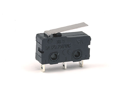
If you use this micro switch it'll work great for your signals . You can do it 2 ways. If your using the tortoise type switch machine mounted under the table you place the micro switch where the wire that moves the switch points(On your track) will just hit it and close the switch. Looking at the micro switch you'll see it has 3 prongs . One of those is power .The other 2 are for your signal one will go to the hot lead of your green light and the other to the hot lead of your red light

So with the tortoise operating rod laying against that metal tab on top your signal will be green . When you press the button on your control panel to activate your turn out the tortoise's operating wire will move away from the micro switch and change the signal from green to red.

The second way to do it if you have DZ switch machines which I don't, I use under the table R/C aircraft servo's but you can mount the switch beside the DZ machine and attach a short wire to the DZ operating lever with a 90 degree bend on the end that will contact the micro switch(So the wire will have enough area on the end to hit the tab).

Same principal- when the short wire has that tab on top of the switch compressed your signal is green. Throw the switch, the lever moves the short wire away from the micro switch and your signal turns red.

Mounting for either way is done by using 2 screws in the center of the switch but I recommend mounting the micro switch on a small piece of sheet metal or styrene with ovaled holes for attaching it to your layout so you can get it adjusted just right.


David

Hello Michael,


In an earlier post I mentioned that I would try my earlier recommendation out once I returned from Germany. Well, I am home now.


I recommended that you could use a 5V DC solid state relay similar to this eBay listing:

http://www.ebay.com/itm/New-So...;hash=item3cc18e47ba


I connected it to a gateman set at 12 V AC that I intended to have operate when the Fastrack turnout is in the out position and it worked perfectly.


Using the fine instructions provided by JoetheBro this is how you would wire your signal to the 5V relay I identified above.


Post 1 to the orange wire from your signal

Post 2 to ground

Post 3 to the black wire in your Fastrack switch controller

Post 4 to the yellow wire in your Fastrack switch controller


This wiring assumes that you want the orange wire to go to ground when the turnout is in the out position. If this is backwards for you and you want orange to ground when the turnout is in the thru position then you only need to switch the yellow and black wires (post 3 and 4).


@gunnrunerjohn - I am happy that this worked as I remembered as I hate to give bum advice. These relays are perfect if all you need is a SPST relay. They are physically big and easy to wire, much easier than my pcb mount micro switches.


Cheers

Denny

Hi all,


I skimmed through this thread, so I apologize if I'm repeating info.  The easiest way add position detection to any twin-coil type switch machine for integration with Custom Signals' system is to use the Atlas #6924 non-derailing board.  The same wires that drive the "out" and "thru" terminals on the FasTrack switch get wired in parallel to the "IN A" and "IN B" terminals on the #6924.   The board features two SPDT latching relays and a dedicated output that provides GND to the TSC-1 or TSC-2.

After careful thought, I am happy with the idea of the micro switch. I hope to drive Atlas CPL or PRR Position signals with these switches. However the microswitch might help me determine yard switch positions... to throw a wrench into the mix, MTH also makes a CPL Dwarf which is available at my LHS.


I did discard the Ross on the bay and have real trax coming. (Yes they will be permanently mounted.) Everything is in a state of change as I learn what works well.


I am not exactly ready yet for signalling, however am aware that I will need some kind of fast visual feedback from the switches in the yard and safety using the 2 block 3 system of approach. Running through switches incorrectly is not welcome.


I apologize if I was hard on anyone.

Originally Posted by Lee 145:

After careful thought, I am happy with the idea of the micro switch. I hope to drive Atlas CPL or PRR Position signals with these switches. However the microswitch might help me determine yard switch positions... to throw a wrench into the mix, MTH also makes a CPL Dwarf which is available at my LHS.


I did discard the Ross on the bay and have real trax coming. (Yes they will be permanently mounted.) Everything is in a state of change as I learn what works well.


I am not exactly ready yet for signalling, however am aware that I will need some kind of fast visual feedback from the switches in the yard and safety using the 2 block 3 system of approach. Running through switches incorrectly is not welcome.


I apologize if I was hard on anyone.

Lee my e mails in my profile. If you get snagged hit me up .We can talk on the phone which is a lot easier to do than me trying to hen peck at this keyboard.
Like I said I'll help anyway I can .

David

I would like to add an aside to the discussion about fixing a micro-switch to the mechanical moving parts of a Tortoise machine. There is no need to do that. The Tortoise comes with two sets of Form-C contacts, which can, in turn, be used to operate as many relays or other devices, via relays, as you need. Adding mechanical stuff where electrical parts can be used is counter-productive, and just adds another place where things can get out of adjustment.

Art I don't have tortoise machines so I was giving a electro-mechanical solution based on the tortoise's operating characteristics . And whats the difference your adding a relay? I'm not using a relay but adding a switch. A switch that's every bit as dependable as the relay . Once the micro switch is positioned and set there is no needed adjustment .

The wire on  the switch machine hits the paddle on the  micro switch and changes the signal. When the turnout is activated the wire on the switch machine moves away from the micro switch and changes the signal.
Mine have been working for 2 years with no problems in O scale and previously for 10 years in N scale so in 12 years they never moved out of adjustment.
A 2 pack of micro switches from radio shack is 3 bucks how much are 2 relays?
To wire the switch up for a signal it takes a hot, a common and the 2 wires going to the signal .

David

Hi DPC,


Art I don't have tortoise machines so I was giving a electro-mechanical solution based on the tortoise's operating characteristics . And whats the difference your adding a relay?

Obviously you've never seen a Tortoise in person.  Arthur is NOT suggesting that a person could add a couple relays.  The Tortoise switch machine has two mechanically operated SPDT switches built into their mechanism (bronze wipers that move across PCB traces).  If you have a Tortoise motor you don't have to spend anything extra for switch position detection.  What's more, if you needed more than two set of contacts for some reason a micro switch would not be an advisable choice for a Tortoise switch machine.  The operating rod on a Tortoise also serves as a spring for mechanical non-derailing.  It is important for proper operation of the points that the pressure applied by the operating rod be roughly equal in either position.  Adding a micro switch to one side creates an asymmetric load that would make it very difficult to properly adjust the point pressure.

Well as you said Dave I haven't seen a Tortoise machine in other than pictures.
My aircraft servo's are mounted under the table and the operating rod on the servo's act as a spring for non derailing just as you describe for the tortoise.
Although the switch in the picture I posted above looks big it's measurements are 3/4" long and 3/8" wide by 1/4 inch thick.

It takes all of about an ounce of pressure to active it, so adjusted correctly side load is not going to be a factor because considering the thickness of the plywood, the micro switch is only a half inch away from the turnout throw bar. I run everything thru the switches from a Big Boy to a Beep with no problems.

I'm using 0.032 stainless steel wire for my operating rods and I even have a coil incorporated into them which consists of 3 rounds around a medium handled X-Acto knife to act as a spring to insure non- derailing  and they operate fine. 12 combined years and they operate fine. I'm using Futaba metal geared servo's which are incredibly strong.

They do have the ability to rip HO track off the ties. Considering the environment they were designed for and the application I'm using them for they'll be under that table and working long after I'm dead and gone.
The servo's need to be centered just like the tortoise although they are programmable for throw rate and distance in both directions which will allow them to  apply considerably more pressure than the tortoise I'm sure.

David

Post

OGR Publishing, Inc., 1310 Eastside Centre Ct, Suite 6, Mountain Home, AR 72653
800-980-OGRR (6477)
www.ogaugerr.com

×
×
×
×
Link copied to your clipboard.
×
×