I want to build a model bridge, about 40-50 inch long span.
It has to be functional for O gauge trains.
I think this will be a fun project to teach my daughter about engineering.
Anybody tried something like this?


|
|
I want to build a model bridge, about 40-50 inch long span.
It has to be functional for O gauge trains.
I think this will be a fun project to teach my daughter about engineering.
Anybody tried something like this?
Replies sorted oldest to newest
It may be more practical to use an existing Atlas or MTH bridge as a starting point and then combine sections to enlarge the size to fit the opening.
For example combining bridges of different styles can be used to lengthen the overall bridge span. For multiple track requirements the bridges can be cut and enlarged (widened).
See various MTH bridges attached.


Not in O scale. I did once build a through truss bridge out of craft sticks in HO, about 3' long or so, to connect two tables of a friend's layout. The sticks were squared off and assembled into I-beams, which were then glued together and reinforced with heavy-gauge stick pins through the splice plates.
I did load-test it by sitting three MTH diesels (about 15-18 pounds) on top of the assembly while it was supported at each end. No deflection was visible. The structure also survived a fall to the floor when one of the tables was bumped before the bridge was securely mounted. Only damage was one of the end trusses came loose. It was repaired and the joint modified to include reinforcing pins.
Had it been wide enough, I probably could have put a Big Boy through it without incident.
---PCJ
Harry, That is a very nice job. I think it was well worth your 60 hours. What did you use for the finish surface? Pat B.
Well here is one i built last year for my layout
it's 8 feet long 2 feet hight.
here pic of it being built it was all hand carver. took about 60 hours to build.


What kind of bridge are you looking to scratch build?
trestle? truss? girder? Have to have some parameters here.
located on the layout or free standing?
straight or curved span?
I think all my bridges are scratch build except my Atlas truss bridge.
Your right, I should have specified.
I want to build a truss bridge.
Pratt or Warren. I'm rather fond of the bowstring type.
Already built, off-the-shelf bridges will not do. The idea is to teach my daughter about structural engineering. Starting with a bridge type, then creating drawings and plans, the construction and testing.
I thought about a kit and found this one:

Definitely strong enough, well engineered, but kinda pricey.
I think we would get more out of it by engineering and building ourselves.
Here are some more websites about building model bridges:
http://bridgecontest.usma.edu/purpose.htm
A Waddell Truss looks like it might be an easy build.

I am looking to build a pedestrian bridge over my garden railroad.
My plan: dig four 36 inch footers; frame them with pressure treated wood, and install ramps both ways for passage. I realize this is a different concept from O gauge, but, the plan is the same: footers, frame it and have a base.
Hope this helps.
I want to build a model bridge, about 40-50 inch long span.
It has to be functional for O gauge trains.
I think this will be a fun project to teach my daughter about engineering.
Anybody tried something like this?
Both are pretty close to each others design- from what I saw.
How many tracks on it?...how many support pylons?
Me, I'd buy an even amount of 3/8" aluminum L or angle stock and line both sides with those- pylon to pylon- then build over and around that in styrene...or wood...whichever you happen to like.
Very cool hah3!
I created 2 bridges with my kids. we started by drawing bridge to O-scale on brown wrapping paper. Got the designs from book "bridges and tressles", which has many plans. You just convert the real size to O-scale at 1"=4ft.
I used pine, cut into 1/4"x1/4" and 1/4"x1/2" pieces. I made this on a table saw, however you may be able to purchase the wood precut, or you could use platic. (plastic I-beams would look better, however more expensive). Using pine wood and wood glue works well and is very strong.
Some pictures to show the method and end results:

draw to scale, then cut the wood to match, place cut wood on the drawing and file as needed to get the correct fit at the joints.


The gussets were cut from mandarine orange boxes using an exacto knife. No balsa wood was used, as this would not give the structural strength need to support the trains.

coffee sturr sticks and slices of orange boxes were used for the various cross supports. I used weights to hold things in place until they dried

The project took time, as I worked in batches, and had to allow time for the glue to dry. I used plastic film (like the kind on a clear cover report) to prevent the glue and wood from sticking to the drawing. I made 4 identical trusses.


Although this bridge looks complex (and is), when you work one piece of wood at a time, it is much easier to build than it looks. You simply follow your drawing, which I borrowed from a published model bridge book.
What is also good about building your own bridge, is you can get exactly the span you need to fill the space. I simply adjusted the span width to give the total length I needed. In the bridge shown, My space was too small for the original design, which would have been 6" between uprights. I reduced this to 4" in order to get the right look. In the end, no one notices how I compressed things.
Good Luck: Joe K


Thats excellent Joe.
Exactly what I want to do.
Thank you. Very encouraging.
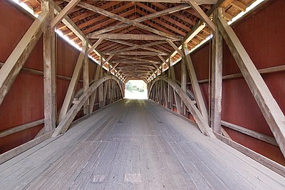
Just a suggestion...check out a Burr Arch bridge design. Many of this type were used in the construction of covered bridges. I'm not sure if that type ever supported a railroad bridge but they were widely used for vehicular traffic. The combination of the arch and truss in the same bridge provided greater strength and load limits than either the arch or truss alone. Many exceeded 200 feet in length.
Two double track bridges, one a plate girder 2 ft long, the second a Warren Truss Bridge 3 ft long. Bridge construction, bass wood strips glued(Elmers Wood Glue) together to make structural shapes and strips cut to make reinforcing plates, track Gargraves Phantom 3-Rail, bridges painted flat black. Considering the construction of a 5 or 6 Ft Warren Truss Bridge. Some may consider these model train structures but given these spans and end pier supports, they are actual functional structural bridges.
Harry's bridge is foam underneath and plaster hand carved stonework. That picture of him sitting in front of it was repeated a number of times while I was there. ![]() That's actually a module that we'll be able to take on the road for our modular layout!
That's actually a module that we'll be able to take on the road for our modular layout!
Replica of the Newport Bridge with two tracks.

Concrete Arch bridges are pretty easy (easy defined as even I can do it) -- a wood skeleton to support the train, and 1/4 luan plywood "skins" for the arch, with trim and moulding pieces for the details. This particular one is 16" high at the rail bed and four feet long. It leads out onto a viaduct which ends on another long, thin concrete arch bridge.


The pylons for the viaduct were constructed similar to the bridge towers. The girders were contact cemented to a "spine" made from HDPE lumber cut into 6' x .75" x 1.25" strips with "ladder rungs" in between to form 2.5" wide bed for the tracks.


Trestle construction is much more involved. The construction of those is on the club website (http://www.angelsgatehirailers.org).
Either way, though, the build is a lot of fun overall and you get a great sense of accomplishment when you're finished and it's sitting in the layout. I'm drawing up plans for a model of the Pacific Electric Torrance bridge which had six arches -- two in the middle for trains, two for the street, and two for the sidewalks, plus it supported tracks on top. They just restored the bridge a few months back. I'd like to build a model of the UP bridge over the Santa Ana River in Riverside, but the model would be close to 20 feet long -- not practical at this time.


Flash,
Thanks for starting this thread. I have not scratch-built an O scale bridge, but it is on my list. Yesterday a friend laughingly pointed out that I don't do any small projects. And so it will be true of this bridge as well.
The plan is to build a shortened (7') version of the center span of this double-track bridge (shown below).

I have not been able to start on this project, although planning has been underway for awhile. I have more than fifty photos of this structure. Several approaches have been considered, but I haven't finalized anything yet.
George
...
George
I love this picture. Would be great to duplicate it in an O scale layout if the space was available.
JohnS, is your bridge wood?
it is tempered hardboard, a water resistant type of masonite.
Do you own the laser?
...
George
I love this picture. Would be great to duplicate it in an O scale layout if the space was available.
Matt,
I grew up looking at that bridge. It is just over 1900 feet long (including the approaches). I intend to model only the raised center spans, but I have to make it fit into 7'. ![]() No problem, right? By the way, in O scale, the bridge would be 39.58' long.
No problem, right? By the way, in O scale, the bridge would be 39.58' long.
George

Do you own the laser?
we now own 2
Matt,
I grew up looking at that bridge. It is just over 1900 feet long (including the approaches). I intend to model only the raised center spans, but I have to make it fit into 7'. ![]() No problem, right? By the way, in O scale, the bridge would be 39.58' long.
No problem, right? By the way, in O scale, the bridge would be 39.58' long.
George
And I thought my bridge modeling fantasy was unmanageable. Yours would be twice the bridge of mine. Now I have "river-span envy."![]()
drew this and cut on laser

John:
Great CAD and laser work. That's better than anything I've seen commercially so far other than brass.
...
George
I love this picture. Would be great to duplicate it in an O scale layout if the space was available.
Matt,
Here are some shots of the prototype just for you!


Enjoy!
George


George, Are these your photos? Very nice. What bridge is this? Regards, Pat B.
Matt,
Here are some shots of the prototype just for you!
Matt, are those girders from Scenic Express or were they scratch built?
George, Are these your photos? Very nice. What bridge is this? Regards, Pat B.
Matt,
Here are some shots of the prototype just for you!
Pat,
Yes, these are my photos. Most of were taken in 2001 with my brother-in-law's Nikon (film) camera. I've actually seen the first photo used on someone's website (without permission or at least a credit).
To my knowledge, the bridge doesn't have a name. The Pennsylvania Railroad would refer to it as the bridge at MP 42.11 on the Panhandle Division. It was originally immortalized in the Grif Teller painting "Crossroads of Commerce" and used in the 1953 PRR Calendar. The bridge crosses the Ohio River between Weirton, WV and Steubenville, OH. It was originally double-tracked. There is an April 2, 1927 issue of Railway Age that details the construction of this bridge (the 3rd on the site).
My father, who is 96, remembers walking across the bridge as a teenager. He told me that when a train came along, they had to grab on to the uprights because the bridge shook.
I was born in Steubenville and grew up in Weirton. To me, this is one of the most fascinating and prettiest railroad bridges in the world. Yet you rarely see photos or find it in books.
If you are interested, my can see my layout (very much a work in progress) on the OGR Photo Forum at: https://ogrforum.ogaugerr.com/t...r-panhandle-division
This is more of a blog than a photo album; in it's 4 incarnations (the previous OGR forum software used to purge entries after so long) it has been viewed well over 45,000 times. This version of web software doesn't keep track of viewings, so I have no idea how much of a following it has currently. I typically note my photos, thoughts, and (lack of) progress every so often. It's useful to me to know what techniques I used, what worked, what my thought process was, and what mistakes to avoid. I hope that works for others as well.
Best,
George
This is a bridge I built from a kit from Plastruct it was a 30" kit but I made it 40" if you buy the kit buy 2 kit to make it longer it is cheaper than buying the extra parts and you can make it wider it come's with plan's on how to build ,I built 2 of them I use one of them for a road bridge it is also 40" long.
Guy


George, It is in fact a beautiful bridge. Thanks for the info. Pat B.
I was born in Steubenville and grew up in Weirton. To me, this is one of the most fascinating and prettiest railroad bridges in the world.
Matt, are those girders from Scenic Express or were they scratch built?
A scratch-built master was used to make a mold, then we cast them in resin. Unfortunately, the mold wore out and the master is MIA. Many of the girders on the viaduct are "seconds" but at the distance they'll be viewed from, you couldn't see the details anyway, especially with the red oxide primer.
Access to this requires an OGR Forum Supporting Membership


