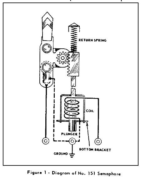
I had the idea that I wanted to use semphores to signal when my track blocks were turned on.  Not really knowing how they worked until I got a couple, I see they are designed to operate from  the tains movement and not from straight electric from the track.  


A quick look and it appears I can wire them to the blocks to signal green when on and maybe have them fall back to red when the block is turned off, although they wouldn't light up  when they should be red.   Does this sound right?   Anybody wired these up so they operate straight from block voltage and not from the trains movement?   I see that probably I should have used block signals, but I liked the semaphores better and this is a make believe world!

Original Post

Replies sorted oldest to newest

If you run them off track power and use modern engines, I would add a TVS on each  semaphore coil. These things can really generate voltage spikes. I would run them off a separate circuit using a dpdt relay. One contact set turning on track power on the block,the other running the semaphore off a separate accessory circuit. 


Switching track power with toggles and relays is described here


http://www.jcstudiosinc.com/Bl...=635&categoryId=


Dale H

Originally Posted by matt b:

I had the idea that I wanted to use semphores to signal when my track blocks were turned on. 


A quick look and it appears I can wire them to the blocks to signal green when on and maybe have them fall back to red when the block is turned off, although they wouldn't light up  when they should be red.   Does this sound right?  

I think the simple answer is if you want the signal to show Red (Stop) when there is no track power to the block, the semaphore arm would be in the down (horizontal) position which requires the semaphore coil to be energized so obviously you can’t use voltage from that track block which would be zero.  If you want to show Green (Go) when the block has power the semaphore arm would be vertical with the light shining through the green lens which means the coil would not be energized. 


But you don’t want to use track voltage anyway because track voltage varies with the desired speed, the type of engine and the load on it (length and weight of consist) so it may not be high enough at all times to supply sufficient power to the coil to move the arm fully down to the horizontal position.


If you’re not using DPDT relays like Dale suggested, you would need a DPDT switch with one pole having track power on the normally closed contact and the other pole having power from another source (an accessory terminal) to the semaphore coil on the normally OPEN contact.  Power to the semaphore light would be constant accessory power.   


And I agree with others that the #151 is not designed to be activated for long periods of time.  Been there, done that and burned a few out!  You’re better off using block signals.


HTH,


Bill

The light bulb on all the time is fine. The coil on for long periods say 5 minutes will burn it up.


I would wire it so the bulb has its power source and common separate from the track. The coil can be powered from this source also. The coil common can be controlled via a relay with the N/O making common for the coil. The track hot would activate the relay.


I would use the postwar block signal and a relay. No burning coils.

One way possibly to reduce the current through the #151 semamphore is as follows:

1) Power the #151 semaphore from an "accessory transformer", independent from the train-powering transformer.

2)  Put a diode, a resistor, and the activating contactor in series with the power to the solenoid.

3)  From the resistor, by-pass the contactor and the solenoid coil with an electrolytic cacapacitor.

When the contactor is "open", power from the accessory transformer will charge up the electrolytic capacitor to full voltage.

When the contactor closes the circuit to the solenoid, the full charge on the capacitor will "kick" the solenoid into action, but the resistor will limit the amount of "holding" current which the solenoid will receive.


I would guess that the resistor would be somewhere in the range of 5 ohms to 10 ohms (5 watts), and the bigger the electrolytic capacitor, the better (maybe 1000 microfarads, 35 VDC).  Experimentation with different values may be necessary.

If I succeed in attaching the diagram, it may make this idea clearer.

Attachments

Images (1)
  • diagram

Has anyone attempted to operate the MTH 151 semaphore with DV as opposed to ac?  I just wired up a new one to ac and it makes so much noise that it's not pleasant at all.  I believe the noise is due to the ac supply to the coil magnet.  Also - I'm finding that it will not operate with the 14vac accessory supply.  Looks like it takes at least 16ac to operate the flag.  Wondering is anyone else has experienced that.

Thanks for posting the diagram of the 151.  Wish the manufacturer would do that.

Stephen

I found 2 AF's on Ebay.  One starting at $50 and one starting at $89.  4-5 of them would more than I am inclined to spend just to get some more "action" on my little RR.   I will keep watching.  I may consider just wiring the 151's in the stock Lionel manner with contactors.   I actually wanted to use them instead of lighted lock-ons, just for the action part.   thanks for all the info.

Thanks guys for your responses!  My timing probably wasn't the best in that I've had family from out of town visiting and they will be here through the end of June.  My young grandson, Patrick (just turned 7) is one of the visitors and we've been sidetracked with other 'train' projects.  Including the addition of a new-to-us Alaska (where he's from) diesel engine to Patrick Station.


I plan on following up with the two issues I've raised and will report back with what I find out as soon as I can.  -Stephen

Post

OGR Publishing, Inc., 1310 Eastside Centre Ct, Suite 6, Mountain Home, AR 72653
800-980-OGRR (6477)
www.ogaugerr.com

×
×
×
×
Link copied to your clipboard.
×
×