Hi guys,
I have been looking through the #6008 Atlas O 3-Rail layouts book, for a track plan. However, when I try to recreate a track plan in Anyrail or SCARM, it looks nothing like the drawing. What am I doing wrong?


|
|
Hi guys,
I have been looking through the #6008 Atlas O 3-Rail layouts book, for a track plan. However, when I try to recreate a track plan in Anyrail or SCARM, it looks nothing like the drawing. What am I doing wrong?
Replies sorted oldest to newest
You really must remember that most of us are not clairvoyant. How about attaching a picture of the Atlas plan AND a copy of your SCARM file? Then, maybe somebody can help you.
Chuck
@PRR1950 posted:You really must remember that most of us are not clairvoyant. How about attaching a picture of the Atlas plan AND a copy of your SCARM file? Then, maybe somebody can help you.
Chuck
I am having issues posting a SCARM file, so I am going to post one and see if it will work. (This is for a separate, standard gauge section, which will run underneath a modified 'Cave Creek Central' track plan by Atlas. It is O-16 on pages 43-44.) I tried to create the Cave Creek Central plan but gave up when it was looking nothing like the image in the book.
Your post of the SCARM file above worked fine; I was able to download it and open it. So, now, how about your actual SCARM file with issues and a photo of that ATLAS plan? Many of us might not have access to that book.
Chuck
PS: I'm signing off for the night, but will look again tomorrow some time.
This is the layout you mentioned. I;m not clear what layout plan you are trying to recreate.
Jan
https://shop.atlasrr.com/p-443...e-creek-central.aspx

I figured I might go with a track plan like these. It was created in Anyrail, as I couldn't get it to work in SCARM. This is more or less what I am aiming for.
I took a look at the AnyRail file settings. One reason the 2 might not match is because AnyRail is more forgiving with it's default track joining tolerances. It joins tracks that are up to .125" (1/8") and 3° apart whereas SCARM uses only .079" (just over 1/12") and 2°. Therefore, if the tracks are "close" to the AnyRail tolerances, they'll join in AnyRail, but not in SCARM and the resulting design in SCARM will end up looking quite different depending on where the disconnects are during the design process. FWIW, RR-Track uses a default tolerance of .05" and doesn't show the angle. It may show that somewhere in the documentation, but I don't see any option to change whatever they use. That said, I'm not saying that changing the tolerance settings in SCARM will solve your problem and get you matching designs. You didn't post your SCARM file, so I have no way of knowing what else might be involved.
Alex,
Just one comment about your multi-level plan; think about what with, or how, you plan to support the upper level, and then think about how that affects what you can see of your trains on the lower level. If you are going to build a table layout, my suggestion would be to keep the lower level on the outside (all the way around) with the upper level fitting in the middle. Conversely (I think??), if your building an around the walls layout, keep your lower level closest to the front and your upper level to the back (nearest the wall) unless you intend to hide what's behind the upper level. Hmmm, maybe not so conversely after all.
Chuck
@DoubleDAZ posted:I took a look at the AnyRail file settings. One reason the 2 might not match is because AnyRail is more forgiving with it's default track joining tolerances. It joins tracks that are up to .125" (1/8") and 3° apart whereas SCARM uses only .079" (just over 1/12") and 2°. Therefore, if the tracks are "close" to the AnyRail tolerances, they'll join in AnyRail, but not in SCARM and the resulting design in SCARM will end up looking quite different depending on where the disconnects are during the design process. FWIW, RR-Track uses a default tolerance of .05" and doesn't show the angle. It may show that somewhere in the documentation, but I don't see any option to change whatever they use. That said, I'm not saying that changing the tolerance settings in SCARM will solve your problem and get you matching designs. You didn't post your SCARM file, so I have no way of knowing what else might be involved.
Adding to what Dave said, from the SCARM blog: http://www.scarm.info/blog/pro...a-given-layout-plan/
Thanks guys for the help. I was able to get things working. I looked at Cave Creek Central and modified it to create my own track plan. I like how it looks, but I'd like some feedback. For example, is there anything that I should change?
I do have some 18 and 21 inch coaches, so is overhang going to be an issue?
Yes, reverse the 2 crossovers at the top left from right hand to left hand crossovers. As now designed, you have a run-around track that you can only exit by reversing.
Do you have enough room to walk all the way around this plan? If not, you will have to build pop-ups in the middle of each loop to access track unreachable from the "front."
Since it appears that O81 is your outside loop and O72 is your inside loop, you should have no clearance problems with your passenger cars.
Chuck
The clearance around your loops varies from 4.0” at the O-54 switches to 4.5” at the #5 switches. Even though the O-72/O-81 curves are wide, I think it’s hard to say whether or not your particular equipment will hit without setting up a test.
Dave,
Good catch on the O54 switches, but I think the bigger issue is that the 21" coaches might not traverse those switches very well at speed, or at all. My recommendation would be to change to O72 switches at the minimum (except for spurs the passenger cars will never used), but my preference would be to use all #5 switches which should insure that all mainline separations stay at 4.5" minimum.
Chuck
I don't have any experience with 21" cars and O54 switches, but I did a version with some #5 switches in the upper left. However, they don't fit in the center or in the upper right due to their length. I was able to replace all but 1 flex track, but flex might be preferred over cutting small fitter pieces. I don't know why the top was so close to the edge, so I moved it down some.


Hi all,
Thanks for the advice. I had the layout against the back wall as the room is 22' 8" x 15' 2". So, if you were wondering about the location of where the layout will be, it will not be an island, but more of an 'around the room' type. Dave, I looked at your changes and I made some adjustments to my track plan. I took notes from you and PRR1950 about clearance issues, so I'm hoping these changes will work.
Update - I managed to remove most of the O54 switches, will figure out how to get rid of the last few.
Works for me, Alex. Good luck with the build.
@DoubleDAZ posted:Works for me, Alex. Good luck with the build.
Thanks Dave!
Made another variant recently, with a turntable. Tried to remove all the O54 curves and replaced them with wider ones where possible.
Like your new variant, just a question and comment. First, do you still plan to run an upper level Standard Gauge layout? Second, would you consider changing the top portion of the Cave Creek based on the suggestion I've attached? Third, and an even more complicated suggestion would be to consider placing your yard within the same loop where you've now placed a turntable. The third suggestion also has the benefit of narrowing your table at the top and making any necessary "reach" a bit easier.
Chuck
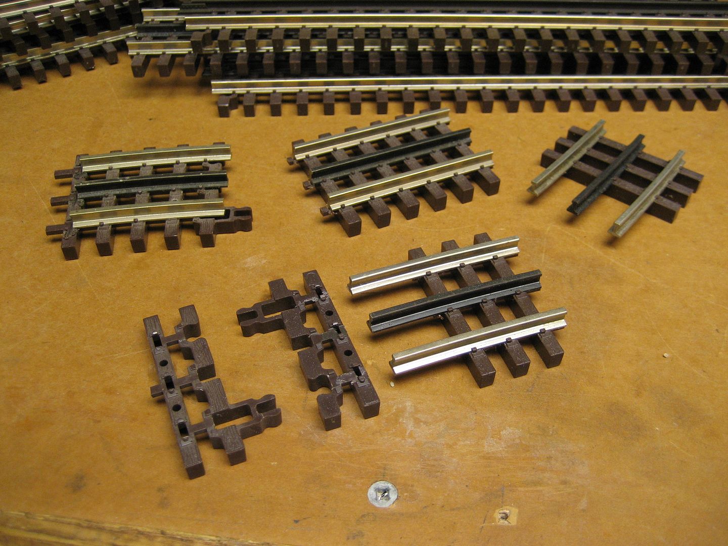
Custom layout may require a few custom track pieces. Atlas has track end pieces for custom cuts.
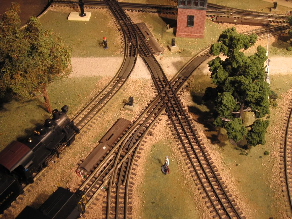
Slight change in direction, gravel road way.
Hi guys,
I have been playing around with track plans again, trying to find the 'Perfect' one. The picture below (V3) is an attempt to see how things would look. The one thing I do kind of worry about, is are my curves too close to the walls? I have included two SCARM files below, one is V2_1, which uses some advice from PRR1950, and the other is V3.
Note: Been thinking of maybe an Over-then-under, type of track-plan, but have no idea how to make it work in SCARM. Always looks like spaghetti when I try.
Red- Doors and AC
Green- Pathway (Where you could walk)

I’ll take a look in a bit, but in the meantime, if you want some help with the over/under, post one of your attempts and I’ll try to guide you through it, assuming you’re having trouble setting grades.
Hi Dave,
I created an over and under loop, minus the grades. I know how to change elevation, etc., but grades... Well, I have no idea. I marked some sections as a bridge, hoping that it will make it stand out from the rest of the loop.
Let's talk about version 3 first. Don't take this the wrong way because any idea deserves consideration, but IMO, version 3 belongs on a scrap heap. The main problem is that your outer oval runs through 2 double-slip switches, a recipe for disaster. Double slip switches should only be used (for model purposes) when you are constructing a yard or terminal; in other words, where only slow speeds are allowed. Running a full speed passenger or freight train through them creates just a "YIKES" moment.
I like that you've moved the yard to the center, but instead of connecting it to the mainline, why not connect it to the inside most passing siding. That way, the passing siding can also double as a yard lead, allowing you to "work" the yard without fouling the mainline.
Version 2.1 is a definite improvement over earlier versions IMO.
Finally, you mentioned the idea of an around-the-walls layout. Generally speaking, that means no part of the layout is more than 30"-36" away from the wall supporting it, requiring no duck-unders to reach any part of the layout. That method also usually requires some sort of bridge or moveable section of benchwork right where the entry door is located. Based on the plan you started with, you could place 2 reversing double track loops (I like to think of them as "bulbs") in the southwest and southeast corners of your room (leaving enough room for access) that then connect to a yard / town along the top. Some people actually put the reversing loops over each other in one corner, place a yard and engine house in the other corner, and then use a rise (or fall, depending on direction) in the two rear tracks of a 4-track mainline along the north wall.
I hope this makes some sense and doesn't overwhelm you!
Chuck
Alex. Unfortunately, you can't do an over/under the way you have it. The green tracks have been raised to 6". The purple tracks are the grades. The green tracks overlap the purple tracks on the loops so there isn't enough separation for trains to pass. The purple tracks in the center that aren't covered are too short, so the grade there is over 10%. The small yellow blocks are 4.5" and the long yellow blocks are 3". Depending on engine overhang, you might be able to get away with 2.5", but I tend to use 3" to be on the safe side. The last thing you want to do is hit a wall.
Re grades, the easiest way to create them is to color-code the tracks that will be part of the grade. Then you can double-click to select them and all you have to do is set the height on one end to 0 and the other to 6. If you need to add tracks to the group to lower the grade, simply change their colors, double-click again and reset the beginning and end heights.
I noticed judicious use of FlexTrack and as a result several straight pieces ended up on angles. That in turn forced some weird configurations in the purple and green upper loops. So, I fiddled a bit and was able to get the grades down to around 5%, still too steep, but progress. Check out the attached files and see what you think.


Hi Dave, would this work?
Would the extra 10" straights help or make it worse?
No, the problem is there isn't enough length to the tracks I circled in Blue to lower the grade below 5% and most want it below 3%, closer to 2%. Now, modern engines can negotiate 5% grades and that's what you get with Lionel's graduated trestle set. Trouble is it's not prototypical, so it's frowned on. It also limits how long your trains can be because even the best engines can only pull so much up steep grades.

Dave, Chuck, and Mike, all good suggestions as usual.
Just putting this out for consideration. Maybe not ideal for operational flexibility or for grade prototypicality, but if the trains only ran in only one direction, they would have a gentle ~2.7% grade up hill (orange) and ~5.3% grade downhill (purple). Perhaps further refinements will allow reduction of the steeper grade if desired...


Playing around with reverse loops, like Chuck suggested. I do like his idea about the loops. Also, I tried to move the track further from the walls.
Alex,
I thought that maybe if I provided some examples you might better understand my suggestions. The more complicated example is an actual layout plan with two "bulb" (reverse loops) at each end of the layout, separated by a peninsula in the middle with a roundhouse. The simpler example is actually a layout "progression" that starts with two ovals designed to look like water-wings, then folds the ends of the oval over itself, and so on. Looking at the simple layout #1, if you placed two 90 degree curves just before each "bulb" and added more straight track down each new side, you would have a "u" shaped layout with the "bulbs" near the bottom. Proper placement of a few switches changes those "bulbs" into reversing loops, if you choose.
Now, you have all that straight track area (minus the 90 degree curves) to plan a yard, industries, passenger stations, and maybe even an engine service area off of the yard on its own peninsula. The only thing to be careful about is that O81 curves will make the bulbs about 90 inches wide. You will have to leave room at each wall for access to all sides of each bulb.
Chuck


It shouldn't surprise anyone that I color coded things to make discussion easier. ![]()
You now have 3 levels. Since I have absolutely no idea what to do, I fiddled with one of the other versions and came up with Photo 2. You can see the grades and heights.


Alex, I got an email saying you posted some changes, but I don't see anything. Did you change your mind and delete it?
@DoubleDAZ posted:Alex, I got an email saying you posted some changes, but I don't see anything. Did you change your mind and delete it?
Hi Dave,
I had made a few adjustments, but I changed my mind and deleted the post. I have attached the file below, if you would like to see it.
I see what you did. Never know when a slight change in perspective will spark an idea. No matter what I try though I can't get both sides of the lower overpass below 4%. When I lower one side, the other side goes up.
@DoubleDAZ posted:I see what you did. Never know when a slight change in perspective will spark an idea. No matter what I try though I can't get both sides of the lower overpass below 4%. When I lower one side, the other side goes up.
Hi Dave,
Thanks again for your help. I appreciate it.
Should my engines and cars be fine with the 4% grade? The longest car is a 21" coach.
Hi all,
I had a question. Will my GN S-2 and 21" coaches be a problem? Or will the 4% grade be OK?
@Lionel2056 posted:Hi all,
I had a question. Will my GN S-2 and 21" coaches be a problem? Or will the 4% grade be OK?
Alex, I would suggest to answer this question that you construct a test track with the grade you're considering and check how well the loco pulls the cars up that grade. If the grade portion of the planned layout also has curves, include those exact curve diameters in the test track as well, because the curves add friction and can decrease the pulling ability of the loco. This will give you a better idea of how many and what types of cars the loco is able to pull up the grade.
Alex, I agree with Steve, but that assumes you have track, etc. if you don’t, you might want to post the question in the 3-Rail forum to get more viewers, but even then you probably won’t find many who have experience with that engine and those cars. Mark Boyce might be able to tell you about the grade test he did for his layout.
Hi guys,
I've decided to abandon the track plan with the 4% grades, as that will cause headaches later on. So, what I did was revisit one of the older track plans and add to it. I am thinking of blocking vision of the train in certain locations, hoping that it makes the layout look larger than it really is. Attached below is an updated track plan:
Alex,
For some unknown reason, I can not download and open your last posted file. I did go back and try one of your earlier files, and it downloaded and opened just fine. Maybe try uploading your last file again.
Chuck
Also, you’ll get more feedback if you post a photo along with the SCARM file. Not everyone has SCARM and my laptop is busy doing an update.
I re-uploaded the file, so let me know if it works/doesn't work. I have posted a photo below. If you want to see the 3D view, I can upload it.

Note that unless these are short locomotives, having curved whisker tracks will be a problem as the locomotives are likely to hit the TT bridge when moving on or off.


Alex,
First off, thanks for re-doing the SCARM link; I was able to download and look at your plan. Now for the comments and suggestions. First, John is correct about the curved spokes from the turntable; they will inevitably give you problems.
Second, you might want to consider moving the coal tower and water tank from current location to along side the track that enters the turntable from mainlines. Locomotives usually stopped for "fill-up" as they left the roundhouse to pick up a train. As now configured, your engines would have to move to the fill track, then move back on the turntable to exit on the departure/arrival track for the roundhouse.
Third, your design still runs from edge-to-edge on the 23' side of the room, and almost runs edge-to-edge on the 16' side of the room. Have you thought about how you will reach a derailment that might occur right at the front of the roundhouse? And, have you laid out the entry angles from the turntable to your roundhouse choice (have you made one?) to make sure you have sufficient space? Trust me when I say that your choice of turntable size and roundhouse kit can have a dramatic effect on the required build space.
I also think your edge-to-edge design is at least partially driven by your choice of very wide curves to accommodate 21" passenger cars. While I appreciate the improved look for those cars, your choices are causing the issues I describe next.
When constructing a plan, one must consider access to all points for either routine maintenance, remodeling (we all see something that needs improvement after we think the job is done), or accident fix. So unless you build with less than a 3 foot reach for all points, you will have to build strong enough that you can walk or crawl on your layout. Alternatively, you can provide access "hatches" (e.g. to solve the turntable derailment reach problem), but many recommend against those because they now require bending and/or crawling under your layout to reach those areas. Never fun as one ages.
Hope this helps.
Chuck
I changed the location of the turntable and roundhouse, moving the whisker tracks as well. Also, I moved the coaling station, diesel fuel depot and water tower towards the exit, so the locomotives can refuel as they leave the roundhouse. I believe I could fit an access hatch, or maybe get a topside creeper. I posted the updated picture above.
Edit: Almost forgot, here's an updated file too:
No graphic, no SCARM, so I can't see it. ![]()
John, he updated the original photo in the 2nd post.
Personally, I don't think a topside creeper is going to give you enough reach into either of the upper corners, and you have no place to put any access hatches that will reach those corners unless you place your turntable and industries on removable hatches. If your room were 4' wider in length and width, you would be golden (2' on each side).
Good luck with your build.
Chuck
Hi guys,
I made a variant without the turntable and roundhouse, but as I eliminated one issue, I believe I created another issue. However, there would be room for an access hatch inside the reversing loop.


Edit: Just made another variant, which I hope clears up the issues regarding clearance. Also, it should allow for access hatches.
Hi guys,
I realized the room is more or less 272 x 182 inches, so the track plan isn't going to work.
So, I have flipped through the pages of my copy of Atlas O gauge track plans and found a good one, 0-30. While an oval, it has O-72 as the minimum curve, with an O-81 and O-90 dual-track mainline, with room for a turntable! So, this seems like a good one to modify into something I'll like. Do you think this could be changed into a folded dogbone?

Not sure if this track plan will work, but could the lower loop on the right-hand side be lowered, or the upper right-hand loop be raised? I kind of like this track plan and would like to figure out how to make it work.

You have plenty of length to gently raise your lowest to your second level and to raise your second level to the third level. However, your layout has several other faults. For example, how do you plan to reach / fix derailments that occur at your roundhouse/turntable or on your figure 8 in the middle? (Remember, it's buried under / separated from you by 3 layers of track.)
If you start to run a train clockwise on the figure 8, how will you ever get it out of the figure 8? Are you just looking for the longest "run" possible for your trains or do you plan to operate? If so, how? Do you plan to include any structures or scenery other than the turntable / roundhouse? If so, where and how?
Don't build something that will bore you within days of "completion."
Chuck
Hi Chuck,
thank you for the advice. I just made some changes and think I got it to work. I could squeeze in some extra turnouts so a train is able to exit the figure eight. Also, I did add a lift gate, where I would stand inside the upper loop.

To me the original design looks like a two-level, out and back design. A train pulling away from the turntable moves to the outer main that is a return loop, raised and folded back. The train ends up pulling in to the turntable because that is the reverse mechanism for the lower loop. So I believe you would have to use the round table on every out and back run. Your modification gives access to the outer loops when a train is traveling clockwise in the figure eight and relieves operation of always going over the round table. I would keep that even with the turntable.
I don't have SCARM so I can't check for sure, but it looks like you don't have that big center loop above the long transition tracks. That big loop is the second level.
@turkey_hollow_rr posted:To me the original design looks like a two-level, out and back design. A train pulling away from the turntable moves to the outer main that is a return loop, raised and folded back. The train ends up pulling in to the turntable because that is the reverse mechanism for the lower loop. So I believe you would have to use the round table on every out and back run. Your modification gives access to the outer loops when a train is traveling clockwise in the figure eight and relieves operation of always going over the round table. I would keep that even with the turntable.
I don't have SCARM so I can't check for sure, but it looks like you don't have that big center loop above the long transition tracks. That big loop is the second level.
I noticed that. The 3D view does show the upper loop above the straight length of track. Maybe it's a bug or something?

@Lionel2056 posted:I noticed that. The 3D view does show the upper loop above the straight length of track. Maybe it's a bug or something?
I don’t see a bug, but the 2D display does make it look like that track connects to the loop. That’s why I color-code tracks to show the whisker tracks vs lead tracks vs 2nd level tracks. It’s kind of a mute point though since the latest design doesn’t have the TT. Without the TT you should be able to add access hatches, assuming this is surrounded by 3 walls. I’m not really sure what a lift-gate gets you, other than a lower balance in your bank account. How much difference is standing just on the other side of some tracks going to make vs standing outside? Do you really want to be turning in circles? Just food for thought.
@DoubleDAZ posted:I don’t see a bug, but the 2D display does make it look like that track connects to the loop. That’s why I color-code tracks to show the whisker tracks vs lead tracks vs 2nd level tracks. It’s kind of a mute point though since the latest design doesn’t have the TT. Without the TT you should be able to add access hatches, assuming this is surrounded by 3 walls. I’m not really sure what a lift-gate gets you, other than a lower balance in your bank account. How much difference is standing just on the other side of some tracks going to make vs standing outside? Do you really want to be turning in circles? Just food for thought.
Hi Dave,
there's an air conditioner nearby on my side of the basement. I'm hoping that the lift-out section(s) will prevent unnecessary damage to the layout, if someone has to work on the air conditioning.
I made some changes as I realized that a train could get trapped in the figure eight. Updated track plan should allow multiple trains to operate.

It looks like you are moving toward a folded pattern. The length of a train will be limited by the circumference of the loop in the lower level turn around if that matters. About 17, 18 feet long.
You may be able to work this plan to avoid the area you want to have access to. One simple mod would be to move the transitions and upper loop closer to the double main at the top. A lot depends on where the transitioning tracks cross under the upper loop and how much clearance there is between the two. Try to keep thinking in three dimensions. It can be a challenge to keep up with grades and clearances while you play with loop sizes, transition lengths, and even the height of the second level. And how will you add scenery to whatever you come up with.
We have similar size constraints. I have a 273" x 120" space and I'm also working in two levels. With more restriction on the sides I am having to design with more hidden track so most of my transition to the upper level won't be seen.
Checked the measurements of the basement and found out it is actually 22 feet 5 inches x 15 feet 2 inches, which meant I had to redesign the track plan again. This layout should allow multiple trains to operate. Maybe could fit a mini CTC control panel to operate turnouts and signals...

Not sure if my measurements are correct, but it might actually be 22' 8" by 15' 2" (272 x 182"). If that is the case, this track plan should work. I took the "New" York Central, O-35, and folded it on top of itself. If you have the 36 layouts booklet by Atlas O, you can find the original on pages 73-74.

I think I got a track plan that I like!

I am thinking this might be a good track plan. Start with the loop in grey, then add the orange and red-highlighted track as I build the layout.

I don't see any sidings, I'd think about adding some parking for cars and made up trains.
Did some work to an older track plan and added a reversing loop. Should be plenty of room for sidings.

Worked on another track plan and made some changes. Might choose this one or the other that I posted two days ago.

You basically have a folded dogbone which is what I have. As you have discovered, it requires duck-unders which drives table height and reduces areas for scenery. That said, my only concern is the track grade between the green-dark gray intersection and yellow-light gray. I am not sure of your dimensions or your minimum grade requirement but that lower left trackage would be my focus.
@Bruce Brown posted:You basically have a folded dogbone which is what I have. As you have discovered, it requires duck-unders which drives table height and reduces areas for scenery. That said, my only concern is the track grade between the green-dark gray intersection and yellow-light gray. I am not sure of your dimensions or your minimum grade requirement but that lower left trackage would be my focus.
You are talking about the two turnouts on the lift-out bridge, correct? I am sure I could fix that when I start construction. I did some work to see if I could get less harsh grades on that left-hand curve that leads to the bridge.

You can simply make the lower level right loop smaller and the upper level right loop larger. That will allow you to start the descent of the trackage near the right wall, then level off at the bridge, and continue to drop towards the left wall.
Made some adjustments to the track plan as I found out that the room is 3" shorter than I thought.

I have decided to modify my track plan into an "Around-the-Room" layout, as I believe this would be the more practical option given the space I have. A couple of lift-out sections allow access to the sliding door and AC, if needed.


Access to this requires an OGR Forum Supporting Membership


