
After reading about dead spots on Atlas O switches, does someone have a diagram to fix the problem.  The dead spots on the track.  Gunnerjohn suggested tight clips and soldering joints.  The problem we have at the museum its not in the joint.  I soldered all 3 rails at the joint.  The dead spot is in the middle of a section.  It's an inch or less long.  Tried cleaning with Goo Gone,  Isopropyl alcohol, &  lightly sanding the the center rail.  Any suggestions.

I thought Atlas O would be easier to work with, I guess not when powered up.

Gerry

Original Post

Replies sorted oldest to newest

@Missabe posted:

After reading about dead spots on Atlas O switches, does someone have a diagram to fix the problem.  The dead spots on the track.  Gunnerjohn suggested tight clips and soldering joints.  The problem we have at the museum its not in the joint.  I soldered all 3 rails at the joint.  The dead spot is in the middle of a section.  It's an inch or less long.  Tried cleaning with Goo Gone,  Isopropyl alcohol, &  lightly sanding the the center rail.  Any suggestions.

I thought Atlas O would be easier to work with, I guess not when powered up.

Gerry

The problem is, if it is a switch, Atlas changed over time how they manufactured them. They used spot welds of copper connecting wires that then get molded into the plastic ties and base structure of the switch. Those spot welds break from the rails flexing and then you lost electrical power conduction. At best it's intermittent and worst completely lost or high resistance. Again, if you flip an earlier Atlas switch upside down, sometimes you can see just barely the copper wire molded inside the plastic ribs of the ties and supporting ribs.

I used a capacitor based spot welder and nickel battery strips after using a Dremel to remove the plastic giving access to the bottom of the rails.

Brand new Atlas switches significantly changed construction and thus less of these connections (more one piece center rail section- specifically at the entrance of the switch).

Attachments

Images (1)
  • mceclip0

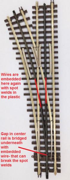
Our club layout had problems with older Atlas switches (circa 2000).  they had thin wires that supplied power to the middle rails.  However, we we had a derailment on these switches, sometimes those thin wires would burn out and result in a power gap to the middle rail.  The best solution was to solder a connection beneath the rail, but the problem was that the section of rail (that you label as "gap in center rail") was composed of some metal that was difficult to solder to.  As a result, we ended up drilling into the bottom of that rail to insert a screw to electrify the rail.

On the switches where we didn't want to pry up, we drilled a hole in the side of the rail (similar to what Steve Horvath suggests) to solder a wire jumper to the nearest powered center rail.

The newer Atlas switches have beefed up power jumpers compared to the old ones.  Also, they have a non-conductive "roller helpers" in the middle of the switch  between your two red lines for the middle rails.  We ended up making our own wooden "roller helpers" for those earlier switches that didn't have them

Add Reply

Post

OGR Publishing, Inc., 1310 Eastside Centre Ct, Suite 6, Mountain Home, AR 72653
800-980-OGRR (6477)
www.ogaugerr.com

×
×
×
×
Link copied to your clipboard.
×
×