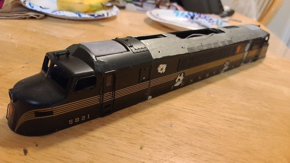
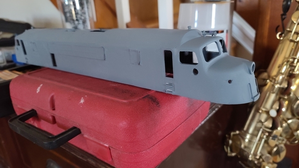
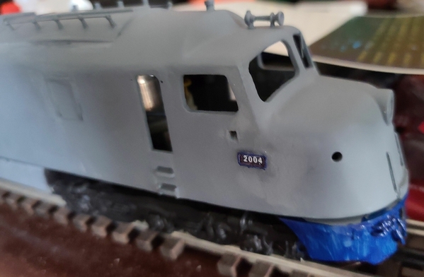
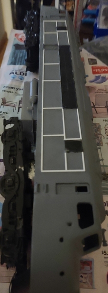
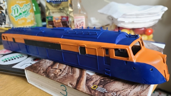
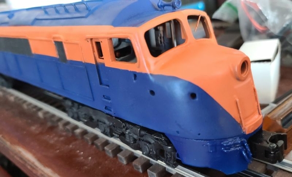
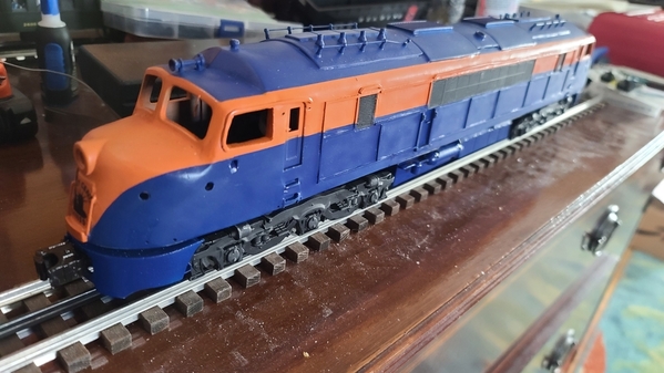
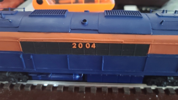
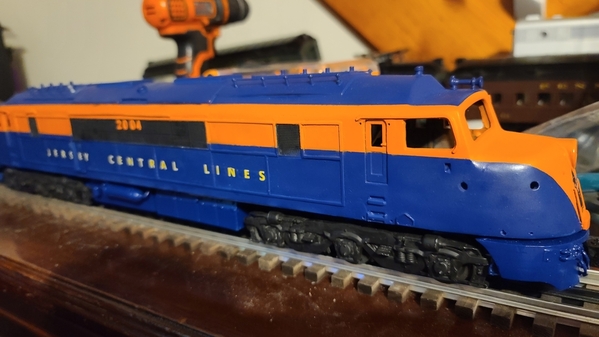
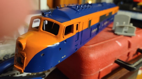
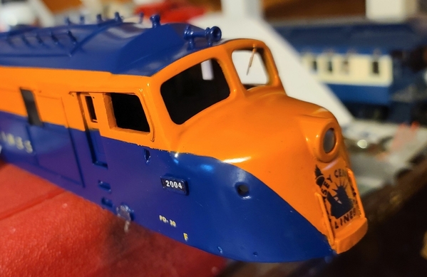
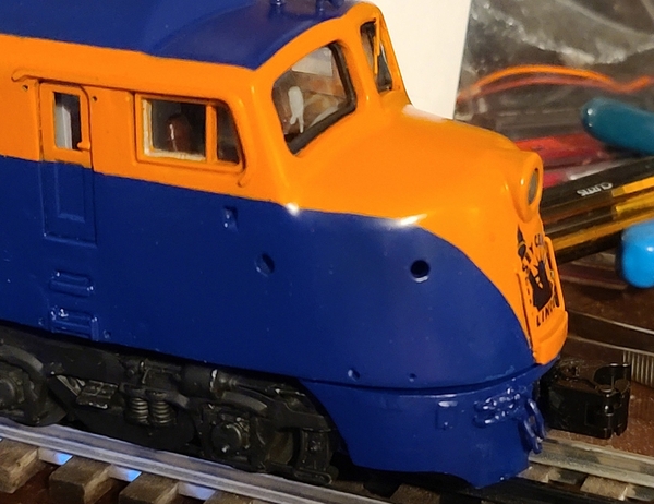
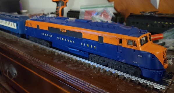
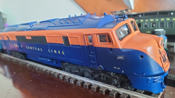
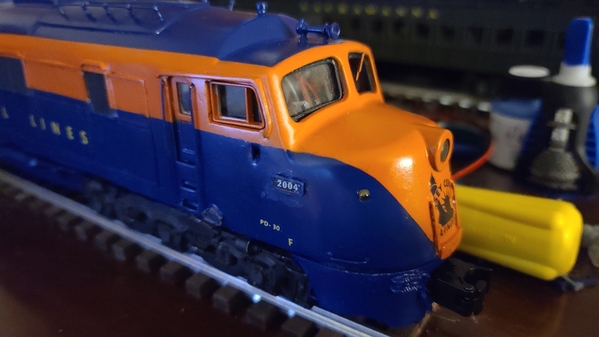
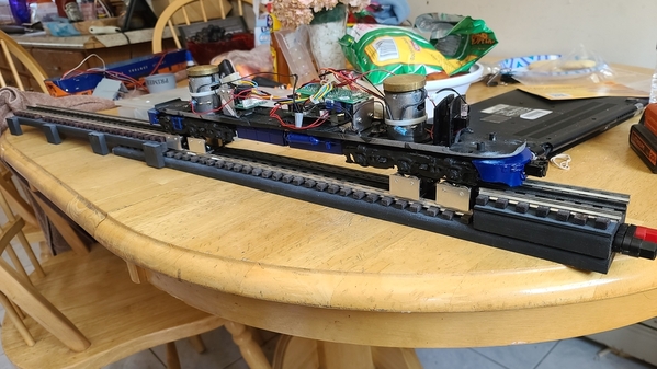
While work has slowed on my CNJ Heavy Mike project due to workspace also being used as classroom space, I figured "what the heck, I probably need ANOTHER half-finished project lying around". So, I give you, the "CNJ DRX-6-4-2000" project. What is it with 3 rails and a general lack of Baldwin diesels? I can find shells to easily make one of these in HO, but other than an obscure kit by the now-defunct Locomotive Workshop, nothing close to these has ever shown up on O scale.

For those unfamiliar, the DRX-6-4-2000 was a double-ended version of the  Baldwin DR-6-4-2000, a 2000 HP passenger cab unit with an A1A-A1A wheel configuration built in 1946. Unlike PRR's "passenger sharks" (which are also DR-6-4-2000s), these used Baldwin's older "Baby face" design. CNJ ordered 6 of them, divided into 2 groups with slightly different appearances.

How to go about building one? Well, after some research, it seems the trucks are the same as those used on Alco PA-1s and DL-109s. The DL-109 is supposedly a better fit, as it's close to the DR-6-4-2000's length. The PA-1 is 12' shorter. After a quick search for a donor engine, it seems the best value I could find at the moment was a Lionel 6-18952 PA-1 that I found on eBay. Has TMCC, which saves on a costly upgrade. Sadly, it only has Signalsounds, instead of Railsounds, but it covers the basics. It'll need to be stretched 3 inches, but that shouldn't prove problematic (says the guy who hasn't yet taken off the Alco's shell).

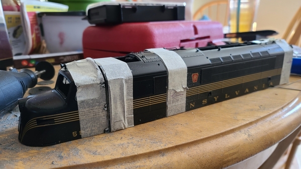
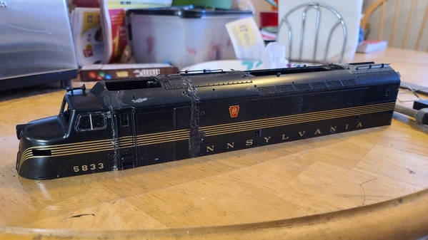
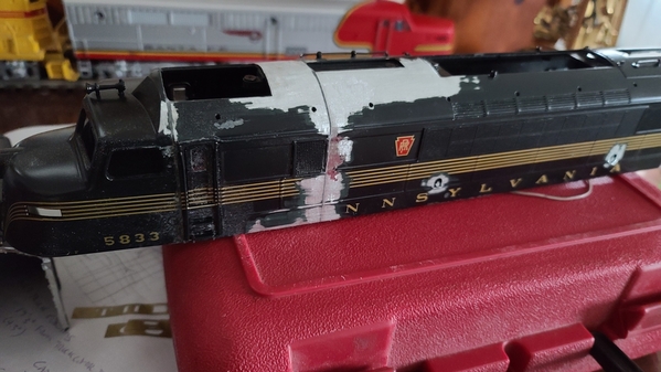
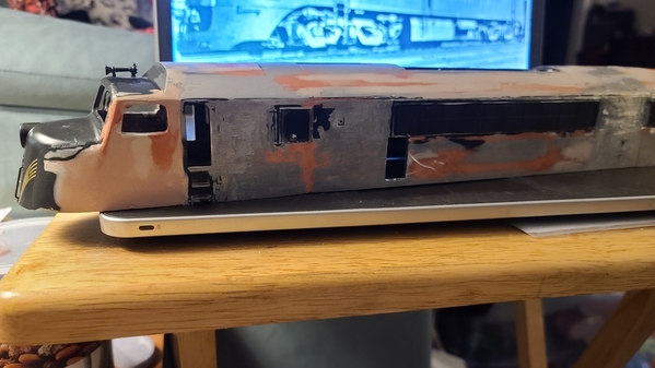
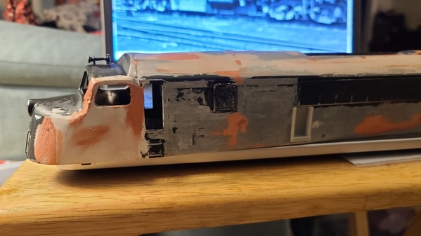
Next comes the trickier part, the body. The ONLY thing readily available with a Baldwin Baby Face profile is the Centipede. Both Lionel and MTH made one, but the cab has an annoying taper starting at the cab door which other Baby Face units like the DR-6-4-2000s and DR-4-4-1500s don't have. I THINK I can offset this using body filler, as it should be less than 1/8th of an inch on the model. I'll have to cut out an inch between the cab windows and the cab door, cut halfway through the first grill (the centipede has 2 grills at either end, and a long set in the center, the DR-6-4-2000 has only 1 at either end along with the long set in the center) and then trim the center section to provide the correct overall length.

Then I have to decide whether to do that all over again for the other end, or make a casting of the first cab and use that for the other. Pics will show up as the project moves along...

Original Post

Replies sorted oldest to newest

Looking forward to the project also. Note, the Centipede Babyface is a different face profile. You may not care as you are willing to deal with the sidewall taper. Just wanted to let you know if it “doesn’t look right” against pics. I too wish someone would make these shells available, hopefully via 3D printing. First Person Scale Models is considering it for a summer project. If interested please contact him, the more interest the better chance it will happen.

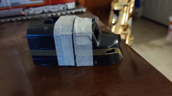
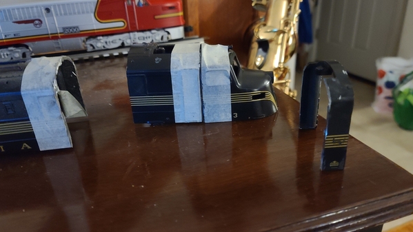
A better modeler than I would have used something like a bandsaw or possibly a bladerunner to ensure straight cuts of the centipede shell. Not having access to a bandsaw, and Amazon jacking up the price of a bladerunner $30 made me decide to try and do the cuts with a Dremel using a right angle attachment. Using a square, I applied masking tape in hopefully straight, perpendicular lines to use as a guide for the Dremel cuts.

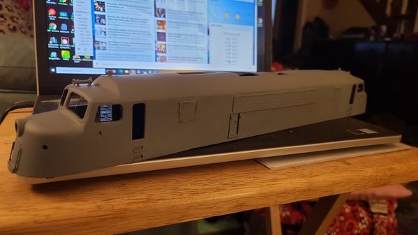
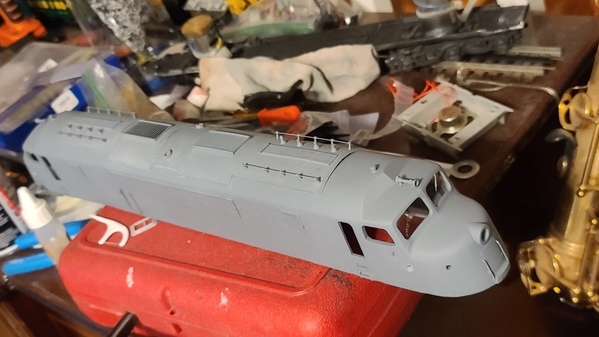
Went through 3 standard cut off wheels on the 1st cut. Switched to one of the larger, reinforced wheels after that, and it did the job on the remaining 2 cuts (there'll be another cut, but I need to figure out how long the center section needs to be before I make that one). Next up, some filing and/or grinding to ensure the cuts are straight and smooth, then they'll be joined together.

20210129_22053120210129_220607

Attachments

Images (2)
  • 20210129_220531
  • 20210129_220607
@Trainmstr posted:

Looking forward to the project also. Note, the Centipede Babyface is a different face profile. You may not care as you are willing to deal with the sidewall taper. Just wanted to let you know if it “doesn’t look right” against pics. I too wish someone would make these shells available, hopefully via 3D printing. First Person Scale Models is considering it for a summer project. If interested please contact him, the more interest the better chance it will happen.

Considering what I'm attempting, and the scanty documentation available on the prototypes, there will be no rivet counting. Other than folks online, I doubt anyone who'll ever see it will have ever seen the original (heck, other than photos I'VE never seen the original). The main difference that I can see is the DRX-6-4-2000 and DR-4-4-1500's noses don't start curving in until past the front of the cab side windows, where the centipede starts curving in right in front of the cab door. The rest of the nose profile might differ slightly, but considering there aren't any models in O scale of the others (and how many widely distributed models of things like RS-3s are incorrect), I'm not sweating it.

As it is, I'll be off a few scale inches on the space between the cab window and cab door, but I want to be sure to leave enough material so that the cab door still operates. If it were a plastic shell, I'd work it closer, but since a die-cast shell is more difficult to work with, I'm not sweating it. I'll be moving the running numbers back to the correct position, and filling in the holes where the centipede's number boards attached.

May take a crack at 3D printing the pilot, if that doesn't turn out well, I can always pick up a couple of the Lionel ones, even if I have to wait until November to get them half off. I've talked to Zach about purchasing his DR-4-4-1500 model, but it's currently in a very rudimentary state.

This reminds me of my project from about 15 years ago...still sitting in a box. Combining the Weaver BF16s A-B shells to make a single BP20 passenger shark A-unit.  This was before Weaver produced the brass BP20. Of course, they were introduced right when I couldn't afford it (2nd kid). Anyway, I chickened out right at cutting the back off the A and the front of the B. So it waits...maybe I'll learn enough from watching your posts to get it out and restart.

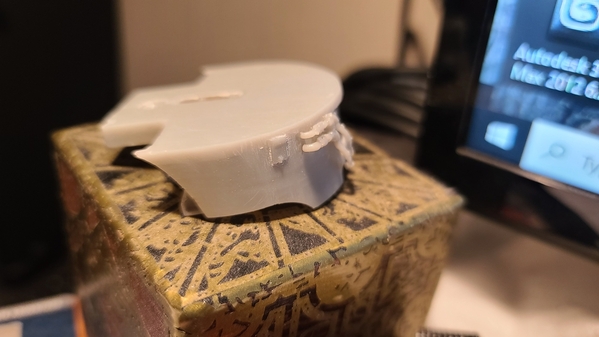
Removing detail. While the sides are similar, the placement isn't, so much of the detail on both the sides and roof will be removed and then replaced. Thankfully a sanding wheel on the Dremel handles this fairly easily. Wish I had better pictures of the roof detail, but surprisingly almost no one seems to take pictures of the roofs of train engines!

20210131_132639

Attachments

Images (1)
  • 20210131_132639

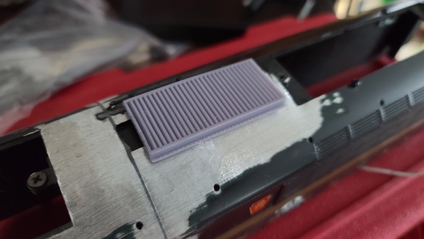
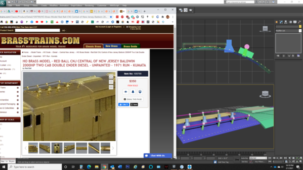
Just a prototype for the roof louver detail, will actually be further back over the "center" section, but at the moment there's a big hole where it goes. Have to work on the rest of the roof detail. Basing it off of the Red Ball HO brass model, figure that'll be as correct as anything else out there. https://brasstrains.com/Classi...nted-1971-Run-Kumata

20210201_134326

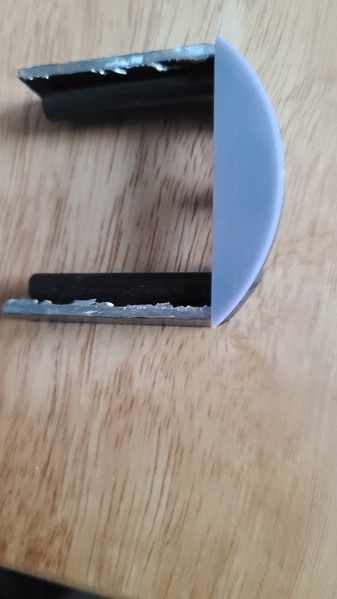
Also printed out a jig to see if I have the curve of the roof correct for roof panels I'll be printing. Looks great except for the corners, which will be adjusted.

20210201_135826

Attachments

Images (2)
  • 20210201_134326
  • 20210201_135826
Last edited by Magicland

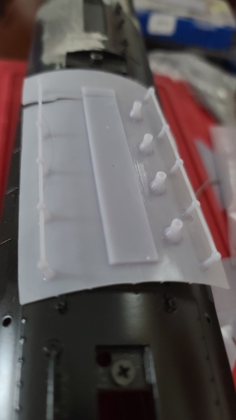
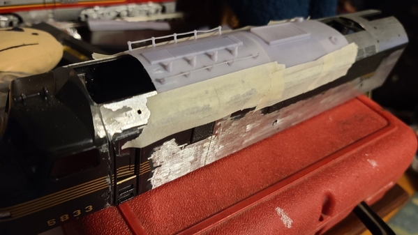
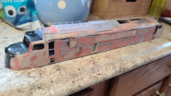
Okay, everything for the roof detail is done and scaled correctly. Just taped in place at the moment (2 panels will be repeated and reversed on the other end), the roof will need to be filled in and smoothed out for painting before it's applied. Glad it looks like Baldwin just riveted on 5 panels (of disparate size) on the roof! I have most of the detail removed from one side of the body (I'll re-add it correctly later). Donor shell for the other cab is on its way, will hopefully show up this weekend if the snow hasn't slowed delivery.

While researching, I discovered that the Red Ball brass has a fairly serious error. The small door in the side of the locomotive is located in the same spot (relatively, ie., on the "left" end no matter which side you view it from), and they have it towards the rear of the engine (the end without the air tanks) on both sides. Tricky, as I could only find one picture of the prototype's left side. This is why you can't blindly base your models on other people's models.

Once the entire shell is together and unwanted detail is removed, I'll move the running numbers back, drill for the marker lights, and re-shape the cab slightly.

20210203_172652

Attachments

Images (1)
  • 20210203_172652
Last edited by Magicland

Today's progress, it's now a double-ender! Even more incorrectly located detail to be removed (sigh!). I'm printing the headlight lenses, side grill numbers, and hopefully a cab side window that didn't come with one of the donor shells (if that works, I'll take a crack at the windshield). I've compiled a list of detail parts I need to design/print, including the undercarriage detail, there's still a ton of work to be done, but it's moving along!

20210206_190853

Attachments

Images (1)
  • 20210206_190853

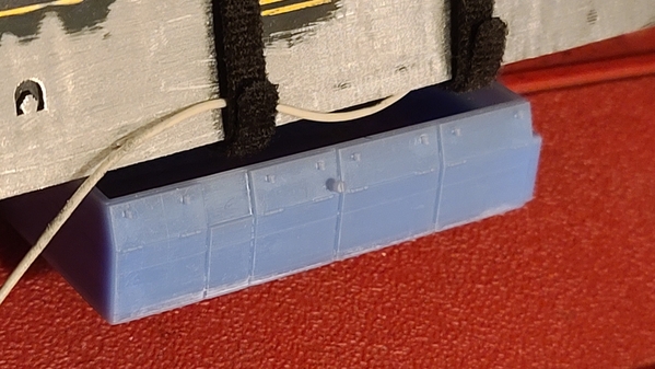
Most body detail removed. Started designing undercarriage detail, first test print done (parts of the latch handles are missing, forgot they needed supports). Currently working on the "front" grouping with the air tanks. Probably dis-assemble the PA-1 "donor" this weekend, and figure where best to cut it to add the needed 3". Then once it's stretched, I'll finalize the undercarriage stuff and print that. Meanwhile, filling and smoothing the body progresses...

20210209_174559

Attachments

Images (1)
  • 20210209_174559

Tomorrow I see if I can reshape the nose to eliminate the centipede's taper (waiting for filler to cure). Meanwhile, back at the ranch, I've been playing around with builder's plates. This pic shows one about an inch wide, which is still way too big. Have ones less than half that size, but working on improving legibility (number and build date are incorrect on this first prototype, current ones are correct)...

20210210_192546

Attachments

Images (1)
  • 20210210_192546
Last edited by Magicland

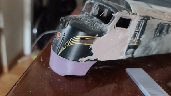
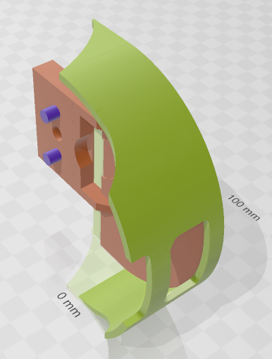
Pilot is ready to prototype (I've got another item in the printer currently, so it'll have to wait, rendered image provided until then). Apparently the thicker die-cast shell doesn't fit on a chassis made for a plastic shell, so that's going to need modified, hopefully I can thin down each side rather than have to cut things.
2" speaker from the "donor" engine won't fit in any of the undercarriage pieces, so I'll either need to find a smaller 8 ohm one, or relocate it.

Going to cut the chassis, and attempt to slim down the sides while I'm waiting for the printer...
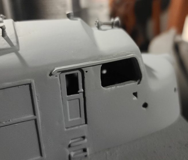
2021-02-13

Attachments

Images (1)
  • 2021-02-13

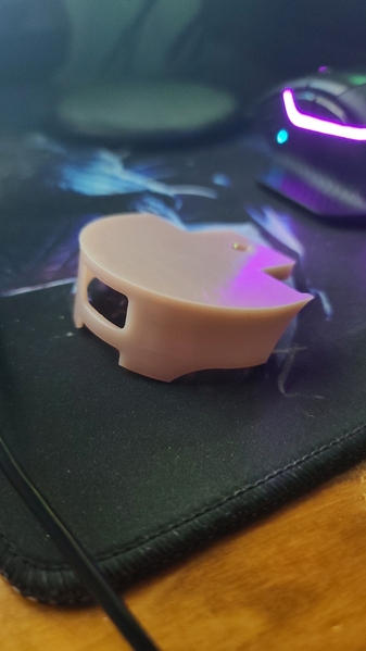
Okay, pilot printed, and it works perfectly. Except for not being able to fit the coupler through the hole where the coupler is supposed to go through. The back of the coupler will go through it, but in order to assemble it without completely removing the truck from the chassis (and I haven't yet figured out how to do that), either the knuckle of the coupler needs to be able to pass through the hole in the pilot, or there needs to be a hole in the pilot so the coupler can be attached, which might be seen as the pilot and truck swivel to negotiate curves.

So I'm faced with either opening the hole for the coupler up to unrealistic proportions to allow the standard Lionel non-scale coupler to fit, or to add a hole on top of the pilot so the coupler can be attached. Will experiment further tomorrow.

Have the chassis separated, and am currently working on fitting both ends into the shell. Have run into a clearance issue with the electronics, which should be able to be resolved by relocating them closer to the center of the engine.

20210213_213316

Attachments

Images (1)
  • 20210213_213316
Last edited by Magicland

Some good progress today! Got both sets of wheels fitting in the shell in the correct position, and a prototype pilot attached. Electrocoupler fits, manual one doesn't. Even though this has TMCC, I don't think it supports electrocouplers. Since I don't plan on using it for a switcher, I can live with it. Now I need to join the 2 ends of the chassis together, and press on with the bodywork...

20210214_155544

Attachments

Images (1)
  • 20210214_155544

Wow, this is coming together very nicely with a lot of skill craft work.   Three of us thought about and actually detail planned to build a model of the similar GM&O passenger Baldwins.   The GM&O's locos were standard single cab baby faces on the same chassis as the CNJ locos.   We even have the MTH Centipede shells to use for making the modifications.   Our GM&O locos would not be as difficult as the CNJ double enders but still a challenge.  We had decided that we would be able to look past the nose side tapers on our models.  We may still get back to this project, with your project as our encouragement.   Nice work.     Brian J. 
@Brian J posted:

Wow, this is coming together very nicely with a lot of skill craft work.   Three of us thought about and actually detail planned to build a model of the similar GM&O passenger Baldwins.   The GM&O's locos were standard single cab baby faces on the same chassis as the CNJ locos.   We even have the MTH Centipede shells to use for making the modifications.   Our GM&O locos would not be as difficult as the CNJ double enders but still a challenge.  We had decided that we would be able to look past the nose side tapers on our models.  We may still get back to this project, with your project as our encouragement.   Nice work.     Brian J.

If you do decide to do it, keep watch for a deal on a DL-109 in case one comes up, as that'll save on extending the length of the chassis. You'll still possibly need to modify the shape of the chassis nose to fit the centipede shell's taper, but it'll be a lot less work than using a PA-1's chassis.

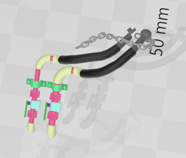
Another snow day, so more time to work on the train! I was working on adding detail to the pilot. Have the 2 brake lines, attempted to print a chain around the ends, but small scale chain is next to impossible to 3D print. There are valve handles, but they won't print unless I change the orientation of the part, which triples the print time. As I'm still prototyping, I'm not worrying about them for now. Also made the hose on the lower line longer after this print.

20210218_135207

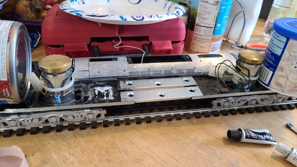
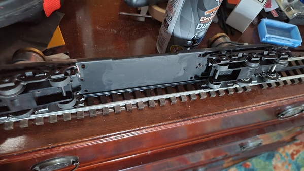
Joining the two chassis pieces together. Wanted something that would maintain the structural strength. Thickest sheet metal I could get easily was 1/16th of an inch, and 1/4" steel bars stopped at 2" wide. Decided to cut a corner bracket in 2, and grind down the ends of each piece on the bench grinder so it would fit better in the hole, while still having a good bit of overlap to provide strength. There's a lot going on in this picture. The shell is being used as a straight edge to keep both ends properly aligned. The track is doing this too. The can of frosting and of chicken are counter-weighting the ends so they don't droop in the middle while they're being joined. I've removed all of the electronics except the motors and a switch (taking pictures as I went along to aid in re-assembly). Once the JB Weld is cured, I'll fill in gaps and holes as needed and clean things up. Then chassis fit will be checked, and mounting holes will be marked and drilled.

20210218_134003

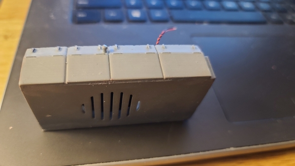
I've located a speaker that will fit in the undercarriage detail, and have added grill cutouts as well as mounts for it to the detail. Once the chassis cures, I'll check placement of the undercarriage detail to ensure that the trucks can rotate properly, and shorten it if needed before printing out final versions.

UPDATE!

And here she is, for the first time, sitting on her newly fabbed chassis! Undercarriage detail is still just placed beneath it prior to clearance testing and final fabrication.

20210218_192950

Attachments

Images (3)
  • 20210218_135207
  • 20210218_134003
  • 20210218_192950
Last edited by Magicland

Been working on it all day, but not a lot of progress to show yet. Decided to print the undercarriage and pilot detail separately to get the best results, then assemble them. Airtanks, pipes and filters have the glue drying, as does the fuel tank and it's sides. Speaker will be mounted in the fuel tank (grill is molded in the bottom). Pilots are printed, just waiting on the hoses to print. Once all the adhesives have cured, I'll hit them with a coat of primer. Paint was supposed to be here yesterday, but the good ol' USPS is up to their unreliable selves (had 2 different packages they're late delivering). Going with Tru-Color's C&O and B&O blue (TCP-072) and CNJ Tangerine (TCP-295).

20210221_225954

Below is the detail for the brake hoses on the pilot, chain was supposed to go around the hoses and be hooked through the lower pilot opening, but it seems it's impossible to get the chain to print correctly. I may just go with some actual chain. Never mind the colors, they're just to help differentiate parts during construction, it all prints the same.

2021-02-21

Attachments

Images (2)
  • 2021-02-21
  • 20210221_225954
Last edited by Magicland

Undercarriage detail primed, drilled for mounting, and with speaker mounted. Found one from Mouser that both fit the fuel tank and the specs of the original one. As the "donor" engine was equipped with signalsounds, it had an 8 ohm 0.2 watt speaker. Unfortunately, the original's 50mm diameter wasn't going to cut it unless it was mounted in the body. May have to upgrade if I ever upgrade to a railsounds system, but this should work for now. Speaker

20210224_19423720210224_193716

Work on the chassis is almost done. Frame sides are now painted black, "stretched" portion has been filled and is just about ready to prime and paint. Still need to mark and drill holes for mounting the shell and the undercarriage detail. I could use a few more snow days, and the couplers and mounting parts that I ordered from Lionel to show up...

20210225_065854

Attachments

Images (3)
  • 20210224_194237
  • 20210224_193716
  • 20210225_065854
Last edited by Magicland

Parts came from Lionel, and fortunately I was able to find a spring that apparently they couldn't, so now the coupler and pilots can be attached at both ends. Not that I'm ready for that, won't happen until they're painted, and hopefully everything will be painted in 2 shots, tangerine first, then blue. Not a fan of cleaning the airbrush...

Roof is filled, sanded and awaiting detail to be attached, which unfortunately won't happen until after I get the sides finished. Most of the bodywork on the cabs is finished, still some final shaping and hand sanding to do, but they're close to what they should be (except for needing to re-add holes for marker lights, running numbers, and sand filler hatches).

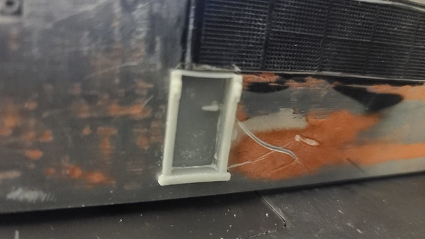
Got the side doors cut today after work. Can't say it was fun, and I managed to break the tips off 2 files (because I'm an idiot who should know not to use them to pry things), but they're there.

20210301_185009

Started prototyping the side doors. All models I've seen have flush doors with windows, however the actual ones were recessed, and I've yet to see a picture of an actual engine with a discernable window in the side doors, so no windows on mine. Cab doors will open, but I don't think it's worth the effort for the side ones. Once I get the spacing and alignment down, detail such as the attachments for the grab irons and door handles will be added.

20210301_212050

Attachments

Images (2)
  • 20210301_185009
  • 20210301_212050

Really looking forward to seeing this as a completed model.  What is the overall length of the locomotive?  What do you anticipate will be the minimum radius for it?  I never saw anything on the CNJ growing up that was blue and tangerine but have seen pictures, they all looked a bit weathered.

@Trainmstr posted:

This is turning out great! Can’t wait to see the cab painted. Do you think using a metal shell rather than a plastic one made the kitbash easier?

Interesting question. I basically went with what was available. I know Lionel and MTH both make Centipedes, but only Lionel shells were available when I started this (and I'm not sure if MTH's are plastic or die-cast). So it wasn't like I had a choice. Given the choice, I'd probably have chosen plastic, as it's a heck of a lot easier to cut, drill, etc. The metal is probably more forgiving to work with, but it definitely takes more work. If it had been plastic, I'd probably have moved the cab door slightly closer to the cab window, but being metal I didn't want to cut it too close and possibly have a weak joint if there weren't enough metal on both sides. 

@necrails posted:

Really looking forward to seeing this as a completed model.  What is the overall length of the locomotive?  What do you anticipate will be the minimum radius for it?  I never saw anything on the CNJ growing up that was blue and tangerine but have seen pictures, they all looked a bit weathered.

It's 20", which is based on the 80' length of a Baldwin DR-6-4-2000 from pulling face to pulling face. Wasn't able find specs or plans of the CNJ's DRX-6-4-2000 variant, so I'm just going to assume they're the same length and run with it. As for minimum radius, The PA1 would do 31" curves before I extended it 3". I'm assuming this will require 42", but haven't tested it yet. As with many O 3-rail models, the pilots attach to the trucks, which while not prototypical, allows a tighter turning radius.

Great on the minimun radius although at 20 inches long it will have some overhang.  I have a vague memory of there being drawings of this locomotive in model railroader back in the late 60s early 70s.  The only reason I have any memory of it is because this was so unique.  If i turn up something I'll forward it to you.

Have the doors finished and printed:

20210302_203105

Hard to see in the photo, but the blocks near the top sides of the frame have 2 nuts on the top and a hole for the grab iron on the bottom. Now to finish smoothing out the sides and mount them...

Finished the detail for the pilots as well, including hoses and the stirrup steps. They're just about ready to be ready to be primed and painted.

20210302_203507

Also finished the cab roof vent pipes. Probably drill and mount those tomorrow, as well as possibly the center roof detail with the exhaust stacks.

Attachments

Images (2)
  • 20210302_203105
  • 20210302_203507

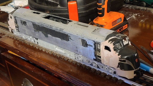
Last of the "ugly" photos (hopefully). Finished with the machine sanding, now for a bit of hand sanding, and a quick coat of primer so I can see if there are any problem areas which need more work. Cab vent pipes are in. Roof detail and side door just sitting in place, will be installed once sanding is done.

20210306_130730

Holes drilled for classification lights and sand fill hatches. Still have to  add holes for the number boards. Final body touch-ups will be done, then side and roof detail added...

20210307_081253

Attached the sand filler hatches, pic of that once they're cleaned up a bit.

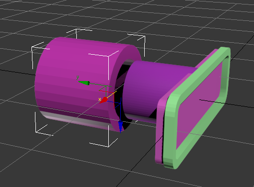
Was trying to figure out a good way to attach the numberboards without having to cut huge holes in the shell like Lionel did for the original ones, since these are located further back and I can't re-use the original holes (which have been filled). Since I want them to light, I'm going to print them with transparent resin. What I decided to to is to attach a 3 mm post (which should act as a light pipe for the LED) to the back of them (which is the same size as the LEDs which I"m using for these and the classification lights). That way I can drill the same size hole I did for the classification lights, mount the number boards flush, and on the inside will be a printed sleeve with a 3 mm hole which will slip over the post on the back of the number boards AND provide a seat for the LED. Concept illustration below.  Once I run off a prototype, I'll adjust the length of the post and sleeve as needed before final prints.

2021-03-07

Attachments

Images (3)
  • 20210306_130730
  • 20210307_081253
  • 2021-03-07
Last edited by Magicland

Feels like I get a lot less work done when I have to go to work. If I stopped going to work, I'd probably be finished already!

Grills have been re-painted and masked off. Sand filler hatches are in. Side doors are in. Still some minor body work to be done before I start adding the side and roof detail. Next up, marking and drilling the holes for the number boards and the lower grab irons on the front(s) and pilots. They'll be attached later so I don't screw them up while I'm still working.

Decided to go a different way with the cab side windows. I don't have them all, and printing one with "clear" resin was producing less than satisfactory results. Changed the frame design, they'll now have clear acetate glued to the rear of them for window panes, the fit is great. I'll probably replace all 4 so that they match. Just wish I knew if they were silver or orange, don't have any good color prototype photos which show them. Same deal with the grills. The B&W photos clearly show they're NOT 2-tone, but are they black or blue?

Anyway, here's where we stand at the moment:

20210310_214137

Attachments

Images (1)
  • 20210310_214137

Magic land,

I checked all my photos, the only thing that would look silver were the stainless steel wrapped around the retractable side window, on each side. Everything else is tangerine, including the vertical post supporting the triangular vent (butterfly) window and the window gutters. Front windshields just have black rubber grommets, no stainless inserts.

Hope this helps.

@Trainmstr posted:

Magic land,

I checked all my photos, the only thing that would look silver were the stainless steel wrapped around the retractable side window, on each side. Everything else is tangerine, including the vertical post supporting the triangular vent (butterfly) window and the window gutters. Front windshields just have black rubber grommets, no stainless inserts.

Hope this helps.

Thanks, that's a huge help!

Making progress, slowly. Spent last weekend and part of this rebuilding my gazebo that came down after that 18" of snow. Drilled for the number boards, but the bit wandered after it got through the body filler and hit the die-cast shell, so I'll need to file and shape them into the correct positions, re-fill, sand and smoothing the damage afterwards.

Started attaching the roof detail. It was nice being able to design the antennas into it, but the reality didn't match up with my expectations, as the resin didn't cure straight enough in such a fine line and I wasn't happy with the results. Plus, it was extremely fragile. Re-engineered them without the antenna cross-pieces and with holes in the stanchions, and ran .020 brass wire. Tried first with holes slightly larger than the wire, but they didn't print cleanly, so I doubled the size of the holes and the wire passes through them.

20210321_105937

I currently have 4 of the 5 roof panels attached, waiting on the last to cure, along with the re-proportioned number boards. After printing out the numbers, I decided to make them shorter, which should also increase the odds of them landing on the flat before the nose starts to taper in. Also made the rods longer, as they were barely clearing the filler and the die-cast shell. Hopefully have a cleaned up and primed pic in a few days. At that point, I just need to do the rest of the side detail and I should be close to painting, probably next weekend. Decals? Yeah, as if anyone had any. We'll burn that bridge when we get to it.

Attachments

Images (1)
  • 20210321_105937

Whew! I'd hoped to have posted more progress pics by now, but I've been down with the Covid. While that would seem like plenty of free time to get stuff done, I haven't had the ambition, mental acuity and temperment all at the same time to get anything done.

Fingers crossed, but at day 10, the odds look good that I'm going to survive this thing and be able to continue my project. Attached the final piece of roof detail this morning. Once I get everything evened out and hit it with a touch of primer, I'll see if I can get a pic up on here. It seemed like a great idea molding in the rivet details to the roof panels, but in practice, I'm losing a lot of it along the way. Oh, well...

Okay, one step forward, 2 steps back department... Was working on the step design for the cab doors, and decided to test with the chassis to see how far down they came. On one hand, I verified that the engine WILL negotiate an O42 curve (it won't look pretty doing so, but it WILL do it). On the other hand, I can't attach the steps to the engine body as I'd planned, as the trucks will knock them off while turning. I'm going to have to figure out some way to attach the steps directly to the trucks. Won't look nearly as good, but it'll work. I believe the donor PA-1 had steps attached to the trucks, now I know why. The steps for the small side doors should be able to be attached directly to the body, as they're beyond the truck's turning radius.

20210331_2017032021-03-31

Attachments

Images (2)
  • 20210331_201703
  • 2021-03-31
Last edited by Magicland

Moving along, slowly. Being back at work has cut into my free time. Roof detail is all cleaned up, gaps filled, etc. Broke off a stanchion on the antennas while doing so, just sanded it down flat to the surface, printed out a few more, glued on the replacement, and back in business! Nice being able to produce your own custom parts.

What's going on here. Ends are masked to ensure correct position for running number boards. 2 holes are fairly close to where I need them, 2 need some work to move them to the correct locations. And yes, though you can't see it from the crappy picture I took, it's sitting on the chassis on track! Still has one of the test pilots, the finished ones won't go on until they're painted, and I'm hoping to do most painting in 2 passes (tangerine, then blue). Not a big fan of cleaning out the airbrush...

Hoping cocktail straws will be close to the dimension I need for the running number boards posts, once the holes are moved to the correct positions, I want to stick them in the holes so they don't get fouled when I fill in around them. Drilling, filling, sanding, more filling and more sanding are on the agenda for tonight. At that point it should be ready for another coat of primer, and then we start attaching the side detail...

20210409_194756

Have the holes moved correctly, cocktail straw "whiskers" inserted (using one going directly across helps ensure they're aligned correctly), JB Kwikweld curing. Straws are out now, but it won't be fully cured until after I'm asleep, so filing, sanding, filling, etc. will have to wait for morning.

20210409_210916

Attachments

Images (2)
  • 20210409_194756
  • 20210409_210916
Last edited by Magicland

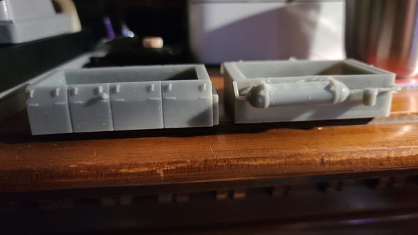
Another 2 steps forward, 1 step back day. Drilled the holes in the chassis to attach the undercarriage detail, and actually got them in the right places! Unfortunately, the resin the detail is made from is rather brittle, and didn't take well to #4 screws. I can obviously just glue on the one with the air tanks, as it'll never need removed, but I'd like to have the fuel tank removable, as it has the speaker in it. Back to the drawing board...

Was going to use cardstock for much of the side detail, as thin styrene tends to curl when cut from sheets. Unfortunately, the cardstock was too thin. Doubled up, the thickness is fine, but after attempting to glue 2 sheets together, it's all wavy, and I haven't even tried to cut it yet. Searched for brass strips as a possible replacement, but none were thin enough, widthwise. After a bit more searching, I found that Evergreen Scale Models makes styrene strips in just about every size imaginable. Measuring the detail on the engine, it seems their .030 x .080 strips are just what I need! So, the side detail is on pause until they get here...

20210410_105852

Running number board shown is just a prototype, the actual ones are shorter, and have longer pegs to connect to the tubes which hold them and the LEDs.

We have a remedy (hopefully)! Since I can't screw into the drilled resin detail pieces, I'll reverse the process. Cutting the heads off some bolts, going to glue them into the holes (producing threaded studs on the detail pieces), and then attach them to the chassis with nuts.

Attachments

Images (1)
  • 20210410_105852
Last edited by Magicland

Crappy week. Girlfriend's ended up in the hospital on Wednesday. She's back home now, but it's taken away a lot of time I could have spent working on this. Got the undercarriage detail mounted. Next up, finishing the remaining blemishes on the body, and applying the side detail. Then, hopefully, we move on to the painting phase. Strips for the sides will allegedly be here tomorrow.

20210418_235217

Attachments

Images (1)
  • 20210418_235217

Just playing around today, real work starts tomorrow!

20210422_172934

Number board test installation, and one of the final pilots sitting in place. It'll come back off and get painted along with everything else. Windows on the cab doors were surprisingly easy to remove, so they've been primed (not shown). This is the "back" end. How do you tell on a "double-ender"? Well, the little "F" on the front end (which obviously isn't there yet) and the undercarriage. Air tanks are towards the front end. There's a bunch of mis-labled crap out there (models, drawings), but this is verified with prototype photos.

Attachments

Images (1)
  • 20210422_172934
Last edited by Magicland

You are correct, later version had air tanks on end designated front. Weird they would change it. As a note, the classification lights are vertically centered with the number boards and closer to the board, I’d say at most 1.5 the length of the number board separating the two. Your number boards should be more forward, left side being even with windshield frame. Not nitpicking!!! Just thought you might want to know. Looking great!

@Trainmstr posted:

You are correct, later version had air tanks on end designated front. Weird they would change it. As a note, the classification lights are vertically centered with the number boards and closer to the board, I’d say at most 1.5 the length of the number board separating the two. Your number boards should be more forward, left side being even with windshield frame. Not nitpicking!!! Just thought you might want to know. Looking great!

Yeah, wanted to be sure that they'd sit on the flat side before the nose started curving, so I was a bit conservative with their placement. I can live with it.

you could do the entire shell in a FormLabs 3L printer (>$10,000).

There is a guy in the Netherlands that would print it but at a cost of 1Euro per ml plus VAT and shipping. So close to $500 (+ VAT and Shipping) for say two shells.  If you want his name and email let me know.

Instead, for a large model I am building I split my model into 3 sections with interconnectors.

@AlanRail posted:

you could do the entire shell in a FormLabs 3L printer (>$10,000).

There is a guy in the Netherlands that would print it but at a cost of 1Euro per ml plus VAT and shipping. So close to $500 (+ VAT and Shipping) for say two shells.  If you want his name and email let me know.

Instead, for a large model I am building I split my model into 3 sections with interconnectors.

Provided, of course, I had a full 3D model of the engine.

Had hoped to get a bit more done this weekend, but... Seems the .080 x .030 strips turned out to be too wide. Depth is spot on. Measured the existing trim with a caliper, but I guess something was off. I'd thought at the time about getting the next size down (.060 x .030) just in case, but thought I had it nailed. Oh well, new ones might get here by Wednesday, managed to order them from some place in York, PA.

DID make some good progress, but not much to actually see. 3 of the posts embedded in the undercarriage detail needed re-seated, that's done. The holes in the chassis to mount the body are now in. Screws from the donor engine are too long (as it had a plastic shell), but I have some nylon 6-32 bolts which I was able to cut down to the correct size. I imagine I'll have to isolate the shell from the chassis for the TMCC to be able to use it as an antenna, so that was going to need to be done anyway. Haven't even begun thinking about re-installing the electronics, I guess it's about time to start.

Think I'm finally done with the bodywork, sanding, filling, sanding, etc. Again, it doesn't look like much has changed, so no pics. Also re-mounted the cab doors, as it'll be a heck of a lot easier getting the paint to align properly if they're painted on the body, rather than separately. Slow and steady, but getting closer to done. Which is good, as I've got a Weaver VO-1000 coming in for paint...

Aaaaand..., after waiting an extra day for the .030 x .060 strips to arrive (only 4 days priority mail from York, PA, next state over, bang-up job those USPS stooges are droing, eh?), I ended up using the .030 x .040 strips that came Wednesday. Could have been done by now. After looking at the 2 side by side on the engine, the .040 strips just looked better, based on the best prototype photo I have.

Only one side is done. Besides it being my mom's 89th birthday, I found that if I attempted to do too much at once before the glue set, I'd just have to re-arrange everything. Would have loved to have gone with a faster setting adhesive, but the pieces occasionally needed a bit of adjustment after placing, so I needed something that wasn't instant setting, wouldn't leave too much of a mess when a piece was repositioned, etc...

Here's an unfortunately somewhat blurry shot I managed to take after moving the engine from the table so we could have cake. Hope to have a better one once the other side is done tomorrow.

20210429_211109

Attachments

Images (1)
  • 20210429_211109

Trying to figure out a few things. Steps, blue? I'm assuming since they're connected to the body (at least on the prototype) and not the trucks, they'd be blue and not black. Builders plate? Any idea what color it was "as delivered"? Pic I have in the original paint (B&W, of course) looks like it blends in with the body, so I'm assuming at least the background is blue. Looks like 2 "Water Fill" labels on the right side (don't have any pics in original paint of the left side). Any ideas about the lettering? "Jersey Central Lines" on the side, tangerine or gold? Hoping the latter because I may have a decal in gold from the passenger cars (have to check size and see if it'll work), anything else and it'll be tough to come up with something, as there are no "O" scale decals available for anything pre-1960s other than cabooses). I THINK I can do a dark blue liberty logo on clear water slide that'll work on the tangerine for the ends. I'm actually excited to be at the point where I need to figure out what color to paint things

Magicland, I own several books on CNJ motive power.

Regarding your question about the color of the lettering, here's a quote from one of the books...

"The body was done in an orange and blue scheme separated by a red stripe.  Initially, the roof was painted orange, but quickly grew black with usage.  The roof was later painted blue and all following orders came this way.  Lettering was the same orange or blue, depending on the background color, and outlined with a thin, red border.  Trucks and undercarriage were black."

Further..."Other cab units arrived in a simplified variation of this scheme.  Gone were the red stripe and border, and gold leaf replaced the orange lettering.  As the CNJ had found out earlier with the switchers, the gold-leaf tended to tarnish and blend in with the surrounding dark background, making the identification almost invisible from any distance.  An engineering directive changed the orange in the gold-leaf lettering color to imitation gold."

Another quote taken from a late '40's photo caption for unit #2004 states...

"Original metallic gold lettering is barely readable and demonstrates why the CNJ quickly replaced it with imitation gold paint".

So depending upon what road # you're planning to model, the "Jersey Central lines" lettering could be orange, gold-leaf...or imitation gold!

Maybe you're already aware of this, but here are some other interesting notes on the original blue & orange paint scheme...

Units 2000-2002 were delivered with orange roofs and had a red pinstripe separating the blue and orange on the car body...with orange lettering.  Even the blue nose heralds--as well as the name (Jersey Central Lines) and road # at the top, center of the car body--also carried a very narrow 1/4" red pinstripe around them...which was barely visible even in the sharpest of color photographs.

Units 2003-2005 were delivered with the "simplified" paint scheme mentioned above...with blue roofs instead of orange and no separating red pinstripes between the body colors or around the lettering and heralds.

As for the color of the steps...the best I can tell from the color builder's photos of class unit # 2000, they were painted black to match the trucks and under-carriage details.  The reason I say "best I can tell" is because the original blue paint was so dark it almost looks black in the color photos!

The builder's plate also appears to be dark blue in the color photos.

Interestingly, I can't see any "Water Fill" stenciling in the builder's photos.

Hope this helps a bit.  I’m enjoying following your project!

Last edited by CNJ #1601
@CNJ #1601 posted:

Magicland, I own several books on CNJ motive power.

Regarding your question about the color of the lettering, here's a quote from one of the books...

"The body was done in an orange and blue scheme separated by a red stripe.  Initially, the roof was painted orange, but quickly grew black with usage.  The roof was later painted blue and all following orders came this way.  Lettering was the same orange or blue, depending on the background color, and outlined with a thin, red border.  Trucks and undercarriage were black."

Further..."Other cab units arrived in a simplified variation of this scheme.  Gone were the red stripe and border, and gold leaf replaced the orange lettering.  As the CNJ had found out earlier with the switchers, the gold-leaf tended to tarnish and blend in with the surrounding dark background, making the identification almost invisible from any distance.  An engineering directive changed the orange in the gold-leaf lettering color to imitation gold."

Another quote taken from a late '40's photo caption for unit #2004 states...

"Original metallic gold lettering is barely readable and demonstrates why the CNJ quickly replaced it with imitation gold paint".

So depending upon what road # you're planning to model, the "Jersey Central lines" lettering could be orange, gold-leaf...or imitation gold!

Maybe you're already aware of this, but here are some other interesting notes on the original blue & orange paint scheme...

Units 2000-2002 were delivered with orange roofs and had a red pinstripe separating the blue and orange on the car body...with orange lettering.  Even the blue nose heralds--as well as the name (Jersey Central Lines) and road # at the top, center of the car body--also carried a very narrow 1/4" red pinstripe around them...which was barely visible even in the sharpest of color photographs.

Units 2003-2005 were delivered with the "simplified" paint scheme mentioned above...with blue roofs and no separating red pinstripes.

As for the steps...the best I can tell from the color builder's photos of class unit # 2000, they were painted black to match the trucks and under-carriage details.  The reason I say "best I can tell" is because the original blue paint was so dark it almost looks black in the color photos!

The builder's plate also appears to be dark blue in the color photos.

Interestingly, I can't see any "Water Fill" stenciling in the builder's photos.

Hope this helps a bit!

Some interesting stuff there, didn't know about the red striping around the herald, letters and road numbers. I'm modeling 2004, so that makes things a bit easier. Also a bit more difficult, as most of the color photos seem to be of the earlier 3. Just about every Baldwin builder's plate I've seen that still has paint on it seems to have the lettering highlighted in some contrasting color, wonder if they used orange, gold, or something else?

If you zoom in on this photo, you can see the 2 "Water Fill" marks, one just to the right of the cab door, the other about the center of the engine. https://i1.wp.com/digitalraila...2017/10/CNJ-2004.jpg

Last edited by Magicland

Put on the gutters over the cab doors and windows, which other than railings, should be the last bits that need added. I swear, every time I look at this it grows more areas that need a touch up though...

20210503_205835

Hopefully by the end of the week I'll have knocked it into good enough shape to break out the airbrush. Heading to the finish line...

Sadly, I lose too much text definition when attempting to print the builder's plate at a scale 8mm, so I have to decide what to do with them. Maybe just the plate, edges and logo and decal the text...

Attachments

Images (1)
  • 20210503_205835
Last edited by Magicland

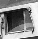
Not sure I'll be able to get retractable windows on there, don't think I have the patience to attempt it. And without any good close-up pictures of the prototype, I'm afraid they're going to be closer to the ones that Lionel put in the Centipedes (though I have moved the divider between the sliding window and "vent" window closer to the front than they did). Running a divider down that piece, with one half tangerine, and the other silver may not be something my eyes are up to anymore.

window

This is the best pic I've got of one of the windows. It's down, mine'll be up. As I mentioned, not sure I can nail that line dividing them and the 2 colors.

Attachments

Images (1)
  • window

Think this is the best I can do. Re-designed the window with an inset frame on the main part of the window (I assume the original sits in channels on the sides and slides down, but that's not happening in 1/48th scale). Ugh, also just noticed that on the prototype, the rear corners of the window opening have 90 degree angles, while on the centipede (which this originally was), they're rounded. Back to the ol' drawing board...

20210506_071227

Attachments

Images (1)
  • 20210506_071227

Looking really good, can’t wait to see it painted. You’re going to have one beautiful loco when completed. My grandfather was an engineer for JC so someone taking the effort to replicate their motive power hits home. I’ll never understand why the manufacturers ignored Baldwin cabs, it’s not like the JC was the only one to purchase them.

It's funny that you can get just about all of them in HO, if not actual RTR engines, at least shells which can easily be built and detailed. I guess in O, with less competition in the marketplace, they build what they figure will sell the most with the least expense to tooling modifications. I was originally interested in a DR-6-1500, as I figured a shark chassis would be a good starting point, and are readily available. However, since they mostly ran back and forth to PA, and the area that I'm "modeling" (once I actually have room for a layout) is South Amboy, it would make more sense for a DRX-6-2000, since they ran regularly on the NY&LB.

I'd like to see one in 2R for my NY&LB, but MY CNJ roster is finally starting to fill out with the shiny new four EMD (I mean 3rd Rail) GP7Ps just delivered.  Still would be a very nice locomotive to add to the roster.  Maybe someday I'll tackle that project.  I still have a fleet of All Nation coaches to build first to put behind the locomotives I have.   

The progress is great.  Looking very nice.

Better hurry, before all those Geeps are running out of Newark Penn...

The impending demise of my dryer delayed things slightly while I replaced it, but they're rolling again.

This is about as close as I can get the silver window frames. At the moment, it's just held there by scotch tape, as it'll need to come back out when the blue goes on, then they'll receive some acetate "glass" before final assembly.

I've (hopefully) printed out the last of the parts, the ladders for the side doors and those little thingies which are just to the inboard sides of the cab doors. Almost forgot to pull the headlight lens I had in for the mockup before I painted! Plan on masking everything and hitting it with some blue tomorrow.

20210513_212611

Attachments

Images (1)
  • 20210513_212611

More fun! Remembered I needed to re-install rivets on the roof panels (why, Baldwin, why?). They were printed with them, but between sanding into shape and several coats of primer, were no longer visible. Fortunately found my rivet decals. No idea where my 3M 1/8 vinyl tape has disappeared to. Also can't find my Micro Sol.

White vinegar (which is basically Micro Set) seemed to work OK.

20210514_125528

As for the missing tape, nobody in the tri-state area seems to actually stock it. Everyone can order it. Heck, I can order it. I believe I had to order it the first time I got some. That's not helping me. In a pinch, figuring it didn't have to stick long if I put it on right before painting, I went with some vinyl electrical tape, as the curves I was doing weren't especially tricky. Also changed my mind about painting everything in 2 shots. Decided I'd do the blue on the roof first, then the blue on the sides, as it made the masking easier. It also gives me a 2nd shot to paint any auxiliary pieces I need again (as 2 turned up missing when I went to paint them). On the bright side, the missing builder's plate turned up, now for the 2nd time as it had previously been lost and found.

20210514_173440

At some point I'll make the missing 2 windshield wipers, but that'll probably be after everything is painted and assembled, as I don't want them breaking off in the process. Still waiting for the decals to arrive, I'll experiment with the electrical tape for masking the noses, and if that seems like it'll work, I'll do the sides tomorrow.

Attachments

Images (2)
  • 20210514_125528
  • 20210514_173440

It turned out to be a lot easier masking the curves on the roof with electrical tape than on the nose. Managed to make do by cutting it with scissors, once everything is dry I'll evaluated how well each side matches the other.

20210515_205652

Next comes some touchups with the tangerine, then a few more shots with the blue, hoping to get both done tomorrow. Picked up a great set of drill bits for the dremel at Harbor Freight which made drilling the holes for the railings a snap. Got word today that the decals were shipping (which probably means they'll actually ship Monday, but at least they're finally on the way).

Then comes all the fun of attempting to re-assemble it. I ordered 2 electro couplers from Lionel. One has normal length wires, the other has wires that are about 2" long. No idea what they'd be used for, but it's supposed to be 2 of the same couplers. Easier splicing in longer ones than attempting to return it and wait, but it's holding up progress. Space shouldn't be a problem, as there's 3" more of it than there was in the PA-1. Speaking of which, the PA-1 had a cab. So now I'm thinking about making cabs for this. Fortunately, they can be added in at any time. Wiring everything up and getting it working should be enough of a challenge for now. I'll have to see what boards are in it (the PA-1 had TMCC, but no railsounds) and if there's any place to hook the couplers and possible directional lighting.

Attachments

Images (1)
  • 20210515_205652

OK, the main painting is done. Still need to touch up the grills. Most models show them painted 2-tone, but the pics I have, at least in the original paint and on the 2nd batch all seem to show them being the same color. Whether that's how they were, or if they just got dirty really quickly (like the RDC roofs), I have no idea, but mine will remain black.

20210516_130921

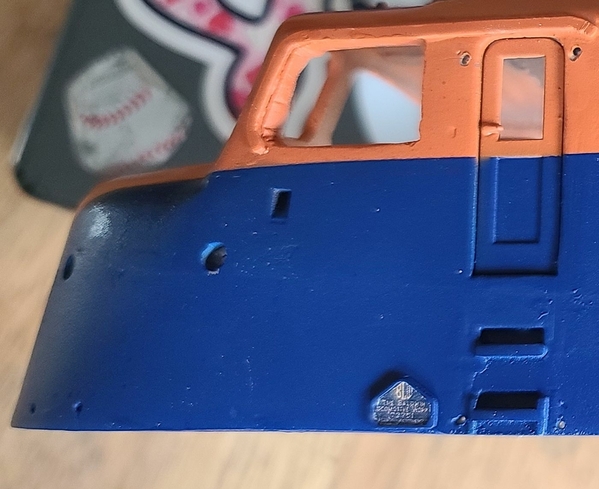
After attempting to scale the builder's plates down to a scale 8mm, I was able to get semi-legible ones at that size, but after several attempts, there was no way I was getting the lettering a different color than the background. That'd be fine for toothpaste stripe models, where they look like the entire plate is just green, but... I compromised, decided to go with a 3-dimensional plate without lettering, and just print the lettering as an insert. If you have REALLY good eyes, you can make most of it out...

20210516_130832

Now to add the railings. I have some .020 brass which seems just a little too fine, have to see what else I can find locally or can order within a few days.

BTW, if your LHS doesn't have the K&S brass product that you need, your next best bet seems to be TrueValue. Around $2 per item (at least for 1/32" brass rods, your mileage may vary) with free ship to store.

Attachments

Images (2)
  • 20210516_130921
  • 20210516_130832
Last edited by Magicland

Don't suppose anyone has any pictures of the cab interior on these? Closest I can find is an RF-16 Shark cab...

Shark has a stepped back wall, but since the engines are reversed in the DRX-6-4-2000 (cab-orientation wise), there'd be no need to bring in the center towards the cab. I assume there'd be a door (or doors, the RF-16 has one on each side, but there might only be one on these).

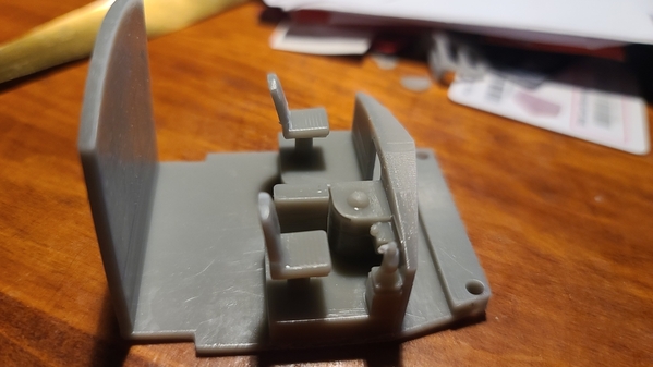
Probably not going to be super-detailed (haven't added the brake stand yet), and the scale of everything in the cab is subject to change, but here's where it stands so far:

2021-05-18 [1)

Attachments

Images (1)
  • 2021-05-18 (1)
Last edited by Magicland

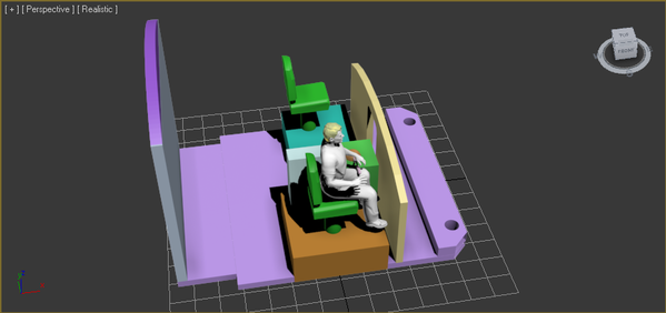
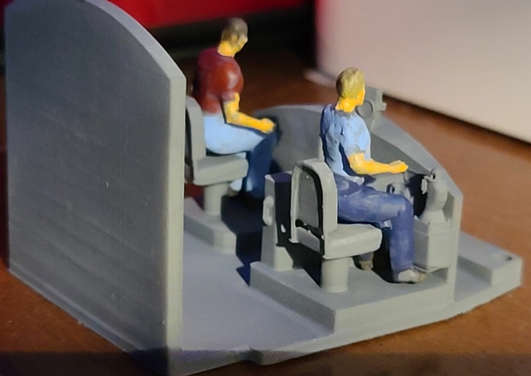
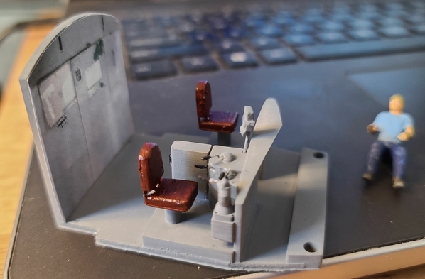
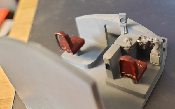
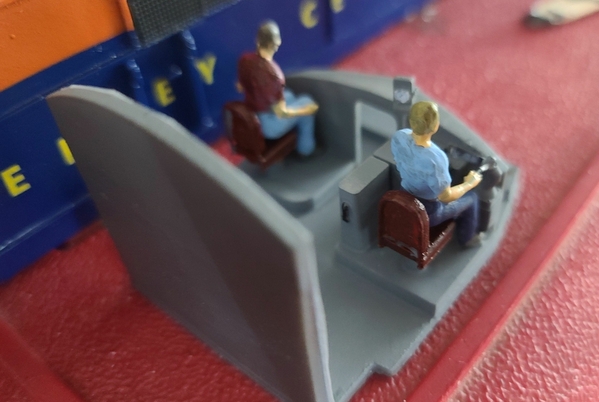
Here's what I've got. This print is super-simplified, just for fitment. I have designed a brake stand, several other things that I don't have a clue what they are, fireman's seat, engineer, fireman, etc., but printing all each time would just be a waste of resin (and I'm running low), so they're not printed here. Early test showed that the handles need to be printed separately. Thought the chairs might need to be too, but they came out OK. Back on the chairs is only supported by 2 posts, one of which broke while cleaning, so I may go with a more robust design.

Main things I was trying to achieve: fit in the space correctly; match up with 2 pre-existing screw holes in the shell for mounting (and thankfully the same screws that hold the pilot on the trucks fit these. I think I ordered like 20 when I needed 1 because the cost was the same); leave room to run wiring between the cab and the chassis for the headlight, classification lights, and number board LEDs. Nailed pretty much everything on the 5th try. Front detail is blurry in the pic, but here it is assembled:

20210519_222328

Decals are in, waiting on the bi-color red/white LEDs for the classification lights, wire for the railings (just got word it's in), and then we're ready to move on to the final assembly stage. Here's where we stand with the interior. Engineer, fireman, speed recorder and the handles will be printed separately. Colors are just to make the objects easier to differentiate in the scene.

2021-05-20 [1)

And we have the first printing (remember, handles and speed recorder will be added on):

20210520_214239

Attachments

Images (3)
  • 20210519_222328
  • 2021-05-20 (1)
  • 20210520_214239
Last edited by Magicland

While a lot of "behind the scenes" stuff goes on, there isn't a lot to see. Waiting for more resin (Sunday) to print the other cab and control handles (did figure out where the reverser goes!). Installed the couplers on both ends, and routed the wire up inside the chassis. Pilots are fitted, but I can't get to the screw to secure them. I think I'm going to have to drill through the chassis to provide access for a screwdriver. Once I drill the holes so I can mount the pilots, I'll see about re-mounting the electronics to the chassis. Then I'll secure the undercarriage details, and the chassis should be pretty much finished. Meanwhile, here's a pic of the body mounted on the chassis with the final pilot in place:

20210521_171253

Attachments

Images (1)
  • 20210521_171253

Feel like I'm finally making progress! Couplers and pilots fully mounted, undercarriage details mounted, electronics mounted to chassis (what fun that was to avoid the undercarriage mounting points). I probably need to lengthen a few wire runs to get it operational (and isolate the body from the chassis to get the TMCC working). Threw on the end decals as I don't picture handling them much, side decals will be applied right before I'm ready to clear-coat the chassis.

20210522_123238

Added the numbers...

20210523_095312

Attachments

Images (2)
  • 20210522_123238
  • 20210523_095312
Last edited by Magicland

Hit everything (except the grills) with a coat of clear satin (which seems to me to be the closest to "O Scale passenger showroom finish", did my 3 Blue Comet cars with it, and they match the MTH factory painted ones very closely). Printed the other cab, drilled both cabs to ensure levers can be attached (very small openings have a habit of closing when printing resin). Now both cabs and the engineer and fireman need painted, once that's done they can be installed in the shell. All the big things are done, now it's "death by 1000 cuts" until it's finished...

20210524_214539

Noticed a problem when I posted this pic. That's the front end, but there's no builder's plate. Seems I put them in the same location on both sides. Was able to detach it with an exacto knife (thank God it was on with krazy glue and not JB Weld!). Left a mess under it though. Had to sand, repaint the area, and then re-clearcoat the entire thing when I got home from work today. UGH!

20210525_194117

Number board, builder's plate, headlight lens. Classification light LEDs should be here Saturday. Windshield is (hopefully) printing. Engineer and fireman are painted. Want to get the windows in before I attempt mounting the cabs (which are currently primed, but not painted).

Attachments

Images (2)
  • 20210524_214539
  • 20210525_194117
Last edited by Magicland

Still have to install the control handles in the cab, if I could manage to get 2 full sets printed. Stuff that tiny isn't easy...

20210525_210513

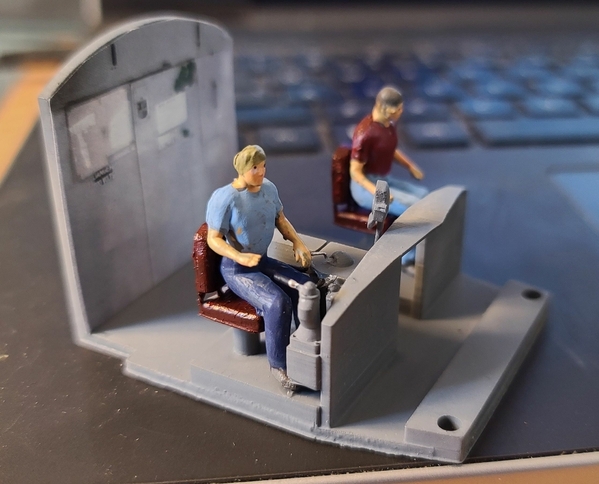
I have printed (paper, not 3D) gauges in the console now, and a printed back cab wall. There's supposed to be a printed dial for the speed recorder, but for the life of me I can't figure out how to cut out a circle that small... Painting the cab tomorrow (mainly the seat cushions and the controller handles), touching up the crew, then I should be ready to install them.

Cab windshield should be just about done, had to tweak it a couple of times, and it's an hour between tweaks to see if it was enough. Last print was very close, but no cigar.

Attachments

Images (1)
  • 20210525_210513
Last edited by Magicland

We have handles! Of course, the reverser is only in the end with the crew, as it should be. Still working on getting the dials in the speed recorders... The entire cab was designed on the computer, based on a few RF-16 cab photos (and modified because there's no HEP equipment behind the cab on this engine like there is on the RF-16, Baldwin located it in the center between the engines), 3d printed in one piece except for the speed recorders and control handles.

20210526_17202720210526_17204020210526_172524

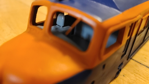
Windows and rear cab installed. Needed to check for clearance for LEDs for the number boards and classification lights. Bi-color LEDs still slated for a Saturday delivery (and since I'm having a BBQ, that's more like a Sunday or Monday install), have extra wiring coming in tomorrow. Miss having Radio Shack around! Still need to add the door window "glass".

20210526_202816

Attachments

Images (4)
  • 20210526_172027
  • 20210526_172040
  • 20210526_172524
  • 20210526_202816
Last edited by Magicland

We’re you in the beach or boro? My first house was on River Rd. in the boro. My three girls were all born at Pt. Pleasant Hospital just down the road, it’s a shame it’s gone. Whenever we visit the area we pass our old house then go over to Manasquan Inlet. Spent many nights, during my younger days, at the inlet watching the submarine races!!

@Trainmstr posted:

We’re you in the beach or boro? My first house was on River Rd. in the boro. My three girls were all born at Pt. Pleasant Hospital just down the road, it’s a shame it’s gone. Whenever we visit the area we pass our old house then go over to Manasquan Inlet. Spent many nights, during my younger days, at the inlet watching the submarine races!!

Beach. It was held at Jenkinson's Inlet. They're ridiculous, charge you through the nose for the event, charge $25 per vehicle for parking, and then won't even reserve you any spots. Lot was full by 11 AM for a 12 noon event, nobody could park. And that's PRE-memorial day. Going to be a zoo this summer. About the only place I'd hit is Point Lobster, mid-week, other than that, I stay away. Over in Manasquan, the Squan tavern isn't bad, but another place I'd only go mid-week this time of year.

I've heard stories about those submarine races, a true sight to (not) behold!

Here's where we stand at the moment...

20210526_214423

Note the builder's plate just in front of the cab door. Shame they didn't run the Blue Comet another 7 years, or we might have seen something like this!

Front cab isn't installed yet, have to investigate some clearance issues between the cab and the number boards. Nothing a dremel and a good bit of cursing can't fix!

Still to do (in no particular order): Railings, LED wiring and installation, cab door steps installation, side door steps installation, door window "glass" (once I get all the glue off my fingers from the cab window "glass" installation), electrically isolate the chassis from the body so the TMCC works.

This last one could be the hardest. I've already got nylon bolts cut to the correct length, but fitting the kapton tape between the chassis and body could be tricky. The fun when you try and fit a chassis made for a thinner plastic shell inside a thicker die-cast body. I've already removed metal from each to get them to mate correctly, but is it enough to allow for the tape thickness? If not, out comes the dremel and more cursing. Tune in next week and see!

BTW, those Lackawanna MU units in the background will be getting some owl eyes and PRR paint once this beastie is done...

Attachments

Images (1)
  • 20210526_214423
Last edited by Magicland

I worked for Jenkinson’s when the family still partially owned it in the 70’s. Used to paint, make candy, and run the beach train. In middle May dig out the tracks for the beach train, was always a rush to get the track cleared and train out of storage and on tracks for Memorial wknd. There used to be a two story concrete storage building in their inlet parting lot. The pavilion at the inlet was still standing and being used in the 70’s, used to be amusement rides by the pavilion too but they disappeared in the 60’s after hurricane Donna. Was in a Jersey Mike’s here in FL and saw a wallpaper pic of me running the train. Have been buying Mike’s Subs since 1958!

I'd like to thank the USPS for keeping my LEDs in Oklahoma city for 6 days (so far). No idea when they'll get here, was supposed to be 2 days ago. Meanwhile, everything BUT the LEDs is re-wired and ready to go. Cab door windows are installed. All railings and grab irons except the side door ones are installed. Getting really close to done.

20210531_163947

Attachments

Images (1)
  • 20210531_163947

And the LEDs are in. Of course, wiring them up is another matter entirely. Not to mention getting the cabs back in (currently full of wire, as can be seen in the pic). And yes, that IS a reverser handle behind the engine, just not one for a Baldwin...

20210603_192313

The classification lights can be white, red or off (not planning on running any second sections, so no need for green. It was hard enough finding the red/white LEDs). Figuring out what to hook them to is another story. Nobody on earth seems to know the pinouts of the LCRU I have (which was originally from the "donor" engine, a Lionel SF PA-1). I've figured out much of it, but as for light polarity, AC or DC, it's all a guess. Going to have to bench it out and see if I can figure it out. Some of these "guesses" are from similar boards, I have no idea if they're active or the same on this one, a 691-PCB1-01B. Just in case you're playing along at home, here's what I've got so far:

J1 - sound connector

Pin 1 – volt +

Pin 2 – volt -

Pin 3 - ?

Pin 4 – serial data


J2 - couplers

Pin 1 – front coupler

Pin 2 – rear coupler


J3 - program switch

Pin 1 – program switch

Pin 2 – program switch


J4 - lights and smoke

Pin 1 – rear headlight

Pin 2 – front headlight

Pin 3 – constant lights

Pin 4 – light ground

Pin 5 - smoke

Attachments

Images (1)
  • 20210603_192313
Last edited by Magicland

Things have somewhat been on hold until I can test out the LCRU board's  outputs. Got the railings installed for both the side doors, and the rollers finally came in for the test track that I need to test the LCRU, so...

20210606_113329

I could just leave the rear part off, as it's not needed for this locomotive, but included it for the pic. Test track (unextended) is 26", and should be long enough for anything I ever throw at it (especially since the longest engine I have is my 2-8-2 Heavy Mike. Power is plugged in via banana plugs at the end, and runs to the whole thing. Now once I test the board's outputs, I can figure out how to wire up the LEDs.

Attachments

Images (1)
  • 20210606_113329

Add Reply

Post

OGR Publishing, Inc., 1310 Eastside Centre Ct, Suite 6, Mountain Home, AR 72653
800-980-OGRR (6477)
www.ogaugerr.com

×
×
×
×
Link copied to your clipboard.
×
×