
Hi all,

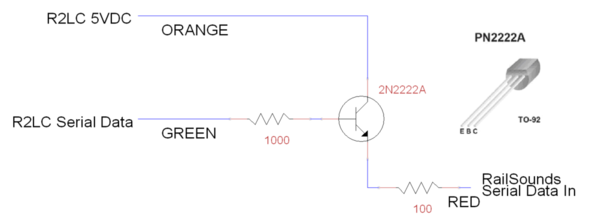
I recently acquired an ERR Cruise Commander M to install in my older Lionel 38095 N&W J class 611, the last of many upgrades I've made to it.  I installed it all per the instructions but I seem to be having issues with the Serial Data Buffer that is supposedly needed to work with the tetherless IR drawbar.  I've heard that it's not needed in some applications due to a board upgrade, but is in others.  The directions aren't very clear to begin with on how to install the buffer in the engine and the wiring in my locomotive is different from what is described in the example photos.  I initially hooked it up as I thought was correct but lost my chuffing sounds.  I removed it and put the modified wiring back to stock and it ran OK conventionally with all sounds but took off uncontrollably in command mode.  This tells me I do in fact need the buffer, but I'm at a loss on how to install it properly so everything works.  Has anybody done this upgrade in one of the J class locomotives that can give me some tips on how to make this work?  It's already gotten upgraded with Gunrunner John's super chuffer and chuff generator for better smoke and 4-chuffs/revolution, but now I'm looking for slightly better running qualities.


Thanks in advance!

Last edited by SantaFe158
Original Post

Replies sorted oldest to newest

I went through the same with my my J. Mine was a runaway at one point as well.

Unplug pin 10 (the one furthest from the heat sink) on the Cruise M and put heat shrink on it. I pulled the 10 pin and removed the wire from the 10 pin and the associated plug on the mother board.

On the 4 pin from the motherboard to the Cruise M, unpin the pink wire and put heat shrink on it. I then used the wire I removed from the 10 pin and put in the 4 pin from the Cruise M to the 4 pin on the motherboard. Looking down on the Cruise M with the heat sink closest to you, the wire will go in the far right position on the motherboard too.

In the pictures I attached the pink wire is still hooked up. It will run this way, but I found issues with it. Do not run it with the pink wire in place. A side note, you will loose your flickering firebox. The center LED stays on like it normally does, but the others come on like ditch lights and will flash/oscillate when you sound the whistle. I have the Super Chuffer and Chuff Generator on the way for mine. The low speed operation with the cruise M is amazing.

Motherboard 4 pin:

Yellow, Black to IR, Blue, Black

Cruise M:

Yellow, Nothing (pink used to live here, went to IR), Blue, Black


Attachments

Images (3)
  • 496844AF-5B66-4241-AB77-10131DA2FB5C
  • 3B04EFE2-BCA9-4E6D-94F7-9D0DD8923981
  • 13FE00C8-DCD5-4436-BCF9-5F878F7CCEEE
Last edited by SPFord27
SPFord27 posted:

I went through the same with my my J. Mine was a runaway at one point as well.

Unplug pin 10 (the one furthest from the heat sink) on the Cruise M and put heat shrink on it. I pulled the 10 pin and removed the wire from the 10 pin and the associated plug on the mother board.

On the 4 pin from the motherboard to the Cruise M, unpin the pink wire and put heat shrink on it. I then used the wire I removed from the 10 pin and put in the 4 pin from the Cruise M to the 4 pin on the motherboard. Looking down on the Cruise M with the heat sink closest to you, the wire will go in the far right position on the motherboard too.

In the pictures I attached the pink wire is still hooked up. It will run this way, but I found issues with it. Do not run it with the pink wire in place.

Motherboard 4 pin:

Yellow, Black to IR, Blue, Black

Cruise M:

Yellow, Nothing (pink used to live here, went to IR), Blue, Black

Call me if need be.

252-312-8726

So if I'm understanding correctly, you essentially removed the DC regulator from the equation and directly connected the CC to the 4 pin plug on the motherboard?

Yes.

Mother board feeds the regulator as it normally does. Remove the ground (pin 10), add in the 4th wire from motherboard to cruise m, remove second pin (pink) from 4 pin on cruise m. The second slot in the 4 pin on the cruise m must be open. If you let the mother board and the cruise m feed the regulator it will not operate correctly. Mine would run and shut down after a while. Let it sit and it would start working again for a few minutes. Pulled the pink wire and it’s been fine since. 

Last edited by SPFord27

I don’t know the details on the regulator. I think I removed both and it had no sound control or chuff. I think what drove me to try it was the harness that came with the Cruise M. It didn’t use pin 2 and the train functioned as it should other than sound control. I added the wire back to the motherboard and all was well. Pin 10 turns it into a rocket.

SPFord27 posted:

Maybe it’s losing signal? Are you testing it with an antenna? It shouldn’t matter with the shell off though. 

It does have the antenna wire lead hooked up still.  I tried attaching it to the handrails out of curiosity but had the same results.  I think I'm going to have to ship it out to one of the experts and have them sort it out.  It's quickly getting beyond my skill level for troubleshooting...

Last edited by SantaFe158
SPFord27 posted:

Do you have a spare R2LC or R4LC to swap in? Check the wires to the run/program switch and make sure it’s not pinched and grounding out. Maybe try to unhook the chuff generator and super chuffer? 

I may have a spare R2LC around from a previous project, but it’s not easily accessible at the moment.  I’ll have to look some more tomorrow evening after work.

Let's keep this topic "open" guys as I'm having the same questions installing a CC"M" in my 38053 NYC Mohawk from 2004. I have Scott Mann's serial data buffer that arrived by mail last Saturday. I started my conversion yesterday and am somewhat stumped by the instructions for hookup of the data buffer.

Has anyone conclusively determined the data buffer is actually needed? It sounds like someone has had theirs operate without the buffer????? If needed, has anyone determined exactly what wire needs this buffer installed and is it installed "in-line" or across two separate lines along with hooking it to a 5VDC power source?

My motherboard in my Mohawk appears to be the same one used in the 38095 "J" - P/N 691-PCB1-10D, so the "fix" needed in the "J" conversion here should also apply to my Mohawk.


Please keep the information flowing until this issue is sorted out and finally put to bed.....

Larry


Jake, try posting this on the TMCC/Legacy forum.

Guns or GGG are your go to guys.

I found this tricky as I installed a Cruise M on a Lionel Dreyfuss Hudson. As you say the instructions are not clear when it comes to steam installations. If I remember correctly the examples are diesels and a Kline steamer.

Check this topic and see if it helps

https://ogrforum.ogaugerr.com/...4-cruise-commander-m

Nick

Thanks for the tips guys.  I think I may have fried something in my attempt to get this working, so I'm throwing in the towel and I'll just be sending it off to John hopefully this week.  I'd rather have the professional make it right than ruin more in my attempts.  Perhaps he'll be able to throw in some tips after his work is finished.

Keep me posted by email of the result. We are trying to compile a list of models that need particular ERR boards and which one's need the Serial buffer or not. It's not intended to be this difficult. Any lessons learned we will use to improve the instructions and recommendations.

sdmann posted:

Keep me posted by email of the result. We are trying to compile a list of models that need particular ERR boards and which one's need the Serial buffer or not. It's not intended to be this difficult. Any lessons learned we will use to improve the instructions and recommendations.

Thanks for your looking out to improve Scott.  I'm sure you guys will make things even better than they are.  In its basic form, it's a very easy installation project.  This locomotive is just a somewhat odd one electronically and might require more work beyond my skills to make things operate correctly.  We'll see what happens.

sdmann posted:

Keep me posted by email of the result. We are trying to compile a list of models that need particular ERR boards and which one's need the Serial buffer or not. It's not intended to be this difficult. Any lessons learned we will use to improve the instructions and recommendations.

Scott,

I have been trying to get in touch with you all since shortly after I installed my Cruise M back in November. I managed to get mine working correctly for the most part as stated above.  When I press AUX2 it will turn the lights on and off as it should but I get a pause or stumble. It it would help I can post a video. The other thing that I wanted to discuss was the loss of the flickering firebox. Is there anyway to get a firmware update to get that feature back? The ditch light outputs feed each side of the flickering firebox board so when you sound the whistle the firebox lights oscillate. 

As far as the operation of the board, it’s miles ahead of the old Odyssey system and made a huge difference in my enjoyment with the engine!

Thank you for keeping these options available!

Last edited by SPFord27

The buffer provided by Sunset Models is not needed on diesels, electrics, or steamers when there is a wired connection to the tender.  In some cases, the output of the R2LC is inadequate to drive both the IR LED in the tether and still provide a digital signal to the CCM.  The directions with the serial buffer require the signal wire to tether be cut and the buffer be put in its place.  The directions with the serial buffer indicate what goes where.  The reason the engine goes to runaway condition is due to the loss of the serial signal.  Adding the buffer ensures adequate digital signal goes to the CCM to provide the control.  And separately (after buffering/amplifying) the serial signal also drives the IR LED in the tether.  Hope this helps!

Moon Doggy: I beg to differ somewhat about the clarity of the serial data buffer directions 3rd Rail has supplied...  While those directions picture what appears to be a K-Line locomotive install, most of us buyers are doing Lionel conversions which do not have the "J3" MB connections pictured. In fact, my install on a 38053 Mohawk has no tether wires of the colors demonstrated in the photos provided. The instructions are not clear as to whether the data buffer is installed "in-line" in one data wire or across a pair of wires.

Another hazard in the instructions is mentioning you may have to solder wires to the R2LC MB connections; it mentions PIN numbers, but how many people know how those pins are numbered? I have to look that information up every time I need to figure that out.

I've done many CC conversions and not had this actual issue with those conversions as the serial data connection was already handled by the ERR product and supplied cables.

Not sure how true the above is.  It has nothing to do with the R2LC, rather how the CCM is coded and works.  As some one posted before, ERR made changes for the latest CCM and one should not be needed.  So the question not answered yet, is this Cruise M an old stock?  Attached are two versions,  the second is to drive the IR tether.  G

Attachments

Images (2)
  • CCM Attenuator
  • ERR IR Booster

I've updated my buffer design on advice from Jon Z.  I changed that 470 ohm resistor to a 100 ohm for more drive.  I also added a base resistor as I don't want unlimited current in the event of some flaw or connection failure.  This is the current buffer I use.

I think some of the confusion about the IR tether is what to do with the 3-wire IR sender vs. the 2-wire IR sender wiring.

Attachments

Images (1)
  • mceclip0

I installed the Super Chuffer II and the Cuff Generator tonight. All was well until I wired in the smoke unit and the engine began to act odd. I lost control like it was in conventional, when it did cooperate the speed steps were way off, and the sounds/signal commands were off. I ended up unseating and reseating the R2LC and reprogramming it using aux1 “4” and it went back to normal. May be worth trying before sending the engine off. I am still running the cruise m as described above. 3 wires from the motherboard to the cruise m, pink wire to the regulator unhooked. 

Last edited by SPFord27

Sean,

Not sure what you mean by, "

Scott,

I have been trying to get in touch with you all since shortly after I installed my Cruise M back in November."

We've corresponded no less than 7 times in December.

We can re-flash Cruise Ms, but they come pre-flashed to us from the factory.

sdmann posted:

Sean,

Not sure what you mean by, "

Scott,

I have been trying to get in touch with you all since shortly after I installed my Cruise M back in November."

We've corresponded no less than 7 times in December.

We can re-flash Cruise Ms, but they come pre-flashed to us from the factory.

Scott,

My timeline was wrong, it was the first week of December after reviewing my emails. I spoke with Rob shortly after installing my Cruise Commander in my old Warhorse. While I was on the phone I asked a couple questions about the Cruise M. He got me pointed in the right direction and I was off and running. After installing the Cruise M I emailed the err@3rdrail email address with questions, concerns, and follow up to what I had encountered (last one was sent on 12/8). The emails went unanswered and I have had a difficult time getting Rob on the phone for tech support. I wanted to share my experience with the installation and provide any pictures that you may be able to incorporate into the instructions. 

My main question after installation was what can I do about the flickering firebox? Can the firmware be reflashed and that feature changed? It sounds like it can. My downfall was not following up with the email I sent on back in December about the flickering firebox and including you on that string.

In order for you to do a reflash, do you just need me to box it up and send it to you? Do I need an authorization number?

I didn’t intend for this to come off as poking at anyone, but I have been calling the line posted on the website. 

Again, thank you for keeping this option available for us! Because of you I was able to convert the rest of my fleet over to command control and plan to finish converting my son’s and fathers over as well.

Last edited by SPFord27
SPFord27 posted:
My main question after installation was what can I do about the flickering firebox? Can the firmware be reflashed and that feature changed? It sounds like it can. My downfall was not following up with the email I sent on back in December about the flickering firebox and including you on that string.

OK, I'm curious.  What does the Cruise Commander M have to do with the flickering firebox?  In any case, I'm sure that 3rd Rail just has the object code for the products they produce, and they won't be making any logic changes to the operation.  Besides, I can't imagine what you're referring to, a flickering firebox feature doesn't connect to the CC-M.

SPFord27 posted:
sdmann posted:

Sean,

Not sure what you mean by, "

Scott,

I have been trying to get in touch with you all since shortly after I installed my Cruise M back in November."

We've corresponded no less than 7 times in December.

We can re-flash Cruise Ms, but they come pre-flashed to us from the factory.

Scott,

My timeline was wrong, it was the first week of December after reviewing my emails. 

Suggestion:  Send whatever you want to say to Scott in an EMAIL.  It's unrealistic to expect him to keep up with any discussion on OGR on a day to day basis--particularly when "facts" are mistated.  Besides, most folks find he's excellent about following up on emails.

In almost all cases Lionel connected the flickering firebox board to track voltage.  I have seen one case where Lionel used a different board and connected it to a point on the command board...a lower volatile output.  None of the CC-M outputs are set for on/off or control of the flickering firebox.  

There are several similar operation (but appear different) implementations by Lionel over the years especially for their early command boards.   As such it is difficult to provide a DIY document that addresses all possible cases.  SPFord27, I hope this helps.

John, don’t tmcc motor drivers have the flickering firebox run buy the board. When you uograde to the CCM, this function is no longer available. I just use the Evans designs fire led kit wired to track power.

if your loco isn’t receiving commands, make sure you’re getting power to the ir tether. Does the light flicker when you send the loco commands?

I haven't run across any of them in upgrades that were connected, that doesn't mean none are.  I know that the CC-M doesn't have any output that would drive the flickering firebox, and I'd bet money and give odds that it never will.

Here are all the connections to the CC-M, no option that would possibly drive the firebox.

I make my own flickering firebox modules.

Attachments

Images (2)
  • mceclip0
  • mceclip1

I will contact Scott directly. I was not trying to poke or say anything negative about Scott and I apologize if it was perceived that way.

Now, back to the firebox issue.

I made a post a while back addressing my issues with the loss of the flickering firebox with the Cruise M. I was told to make one and given the links (thank you to all that provided that information). On the old driver board there is a 4 wire cluster (ribbon) that goes from the 10 pin to the firebox board. From what I can tell (I don't have the engine in front of me), pin 3 or 5 feed the center LED, pin 4 or 6 is the common ground for the LED board, pins 7 and 9 feed the outer LEDs. The center LED stays on and the other four would flicker. The board only consist of tracers, LEDs, and a plug. Currently, the four outer LEDs oscillate when the whistle is blown and the center stays solid. The only wiring change in regards to the addition of the Cruise M and the LED board is the removal of pin 10. To be clear, pin 10 did not go to the LED board. 

As a bonus to the Cruise M, the green jewel lights are now AUX2 controlled with the headlight. 

Attachments

Images (2)
  • Firebox
  • 26A69C6A-90F2-477D-B7D9-845FE74E8906
Last edited by SPFord27
gunrunnerjohn posted:

If you connect them to the ditch light output, that would be the expected operation.  However, that's not how Lionel runs them.

John,

I literally pulled pin 10 out of the 10 pin and plugged the 10 pin connector directly into the Cruise M. Why did they flicker before? There has to be some sort of different programing in the DCDS output compared to the Cruise M. If the LEDs were flickering LEDs they should flicker as long as there is current correct?

I just use the Evans Dedigns fire LED kits and put them in a black piece of sheet stock and mount it to the factory board mount then wire them directly to track power. They run off 7 to 19 volts, they’re always on when track powe is on but who cares, steam engines in the yard always keep the fire burning. It’s part of the CCM upgrade that you have to find work around a for some of this stuff. You won’t get the same functionality out of a universal board that you get out of loco specific factory boards with dedicated firmware. It’s part of model railroading 

Alright, spoke with Scott today and got some clarity on things. Thanks again Scott!

Now onto the flickering firebox. Does anyone know what the output voltage is for LEDs I’m the 10 pin? I spoke with Evans Designs and I am going to attempt a 5 bulb set up using the spare LED board I have and let Evans Designs help me put a bulb kit together. 

Did the original poster figure out his issue or what he plans to to? 

Last edited by SPFord27
K4s-RRA posted:

In almost all cases Lionel connected the flickering firebox board to track voltage.  I have seen one case where Lionel used a different board and connected it to a point on the command board...a lower volatile output.  None of the CC-M outputs are set for on/off or control of the flickering firebox.  

There are several similar operation (but appear different) implementations by Lionel over the years especially for their early command boards.   As such it is difficult to provide a DIY document that addresses all possible cases.  SPFord27, I hope this helps.

There are Lionel Steam engines that used the DCDS 10 pin outputs for marker and/or Fire box LEDs.  Whether it is a feature that can be turned on or off,  I do not know.  But as stated the CCM does not have that.

Lionel did have a lot of variations to Firebox. 

I'm not 100% sure what the final fix was, but my radio board was indeed DOA when Gunrunner John received it.  He also replaced the smoke unit AC regulator board as it was bad as well.  I'm extremely happy with how this engine performs now.  The improvement in low speed running is pretty significant.  It's still not quite at the level of a Legacy engine, but as close as one can get.  The smoke unit fills the room now as well.  John did a great job with it!

SPFord27 posted:

Glad you got it sorted out. It makes a huge difference in the operation of that engine! What headlight are you using? I am still using the stock bulb and it’s not that bright. What is the car behind the tender?

The headlight is a warm white LED powered by one of Gunrunner John’s products (can’t remember which one at the moment).  It certainly makes a big difference.

The car behind the tender is an older MTH N&W Express reefer.  A friend of mine snatched it up at the LHS when the owner took in a collection.  It’s a beautiful car, but not easy to find from what I’ve heard.  It’s not a perfect match for the Lionel paint, but looks close enough when going around the track.

It has the Super-Chuffer, the major problem with the smoke was the voltage regulator.  The R2LC was not only totally dead, but it was the C12 version, which is for one of the accessories, I think possibly the Backshop.  I put the proper C13 R2LC into it, and all was well.

I do like the J Class, every time I get one in for repairs or upgrades, I think about getting one.  Of course, then I'll need a set of passenger cars, etc.

SantaFe158 posted:
SPFord27 posted:

Glad you got it sorted out. It makes a huge difference in the operation of that engine! What headlight are you using? I am still using the stock bulb and it’s not that bright. What is the car behind the tender?

The headlight is a warm white LED powered by one of Gunrunner John’s products (can’t remember which one at the moment).  It certainly makes a big difference.

The car behind the tender is an older MTH N&W Express reefer.  A friend of mine snatched it up at the LHS when the owner took in a collection.  It’s a beautiful car, but not easy to find from what I’ve heard.  It’s not a perfect match for the Lionel paint, but looks close enough when going around the track.

I picked up the MTH aux tender and the 2015 (I think) release of the heavyweights for mine. Found the two REA boxcars the other day, picked up the combo and diner car add on pack along with the mail car. Eventually I want to get the add on coach and baggage car pack, but now I need to add the reefer to the list thanks to your video! 

SPFord27 posted:

I picked up the MTH aux tender and the 2015 (I think) release of the heavyweights for mine. Found the two REA boxcars the other day, picked up the combo and diner car add on pack along with the mail car. Eventually I want to get the add on coach and baggage car pack, but now I need to add the reefer to the list thanks to your video! 

The reefer is really a great car.  I've got the Lionel N&W Aux tender (no stripe), but only run that typically if I pull a freight train with the J or a mix of passenger cars simulating the modern era excursion trains.

Add Reply

Post

OGR Publishing, Inc., 1310 Eastside Centre Ct, Suite 6, Mountain Home, AR 72653
800-980-OGRR (6477)
www.ogaugerr.com

×
×
×
×
Link copied to your clipboard.
×
×