
We have a finished attic with a room measuring 11’ x 16’ actually it is 16’ on one side and 12’ on the other because the wall is angled. The ceiling is vaulted because of the roof line.

BF987692-FF0E-4CD5-9CB8-7D0BFBA94B0E

This is from the door looking into the room.

6B357450-45E0-4E51-B01C-92A6F878F93B

This is from the back of the room looking toward the door with angled wall.

I was thinking it would be better to do benchwork along the perimeter of the room, as opposed to a square or rectangle table in the middle of the room.

I would like to be able to run at least three trains at once, with several sidings to park engines and cars on, as well as a trolly line. I have a few accessories, but not many. The biggest of these is the 364 log loader. I also have the following:

- lots of o31 and o27 track

- 4 o42 switches

-12 1121 switches

-1 o gauge four way

-1 o27 four way

-2 dozen plasticville buildings

-450 signal bridge

I would also like to have a bridge and tunnel on the layout. 

Pretty tall order with the space I have available. I guess the first order of business is to paint the walls of the train room. Any ideas of color? Clouds?

Any help is appreciated. I found a layout on YouTube that I would like to loosely follow as far as detail and scenery go. 

https://youtu.be/dPBtMhPXuVg


Attachments

Images (2)
  • BF987692-FF0E-4CD5-9CB8-7D0BFBA94B0E
  • 6B357450-45E0-4E51-B01C-92A6F878F93B
Original Post

Replies sorted oldest to newest

Allowing for a 2' aisle, best possible table is about 7x12. Consider that on two sides your aisle is going to have a sloped ceiling overhead.

An 11x12 around-the-room layout will work nicely. The height of your knee wall and/or the bottom of the window will be the controlling height of the bench work. One advantage, with lower bench work your top can be wider. I'd suggest 42" max. A peninsula in the center (from window back towards the door) will give you space for sidings/yard area.

Were it mine, I'd do a U shaped folded dog bone with reversing loops on each end.  

Last edited by Gilly@N&W

Hi ASYMAIR95,

Some other considerations:

  1. The knee wall height is higher than the window sill height -- going to the highest point where the slope starts decreases use of table top for train clearance-- I would suggest somewhere between to two heights or just below the window sill. Can you hang the AC units in the top sash?
  2. Speaking of the windows--that table may have to more narrow than the rest -- you'll need access to the windows
  3. It's appears that the long wall has the heat unit-- that table should stand away from the wall to permit good convection--floor to ceiling air flow
  4. Electrical needs--are the receptacles for this area on their breaker in the electrical panel? Are the receptacles on one circuit or separate circuits? Are any of the receptacles switched on/off by a switch near the door? Having clean power and the ability to power the layout on/off at the door are good options
  5. Are you satisfied with the lighting?

I would paint what ever vertical wall is exposed and the ceilings in Sherwin-Williams Tibetan Sky - it is a very light blue - like the color of the horizon over the tree tops on a sunny day- it shows less blue when brightly lit and slightly darker in dimmer light. It is actually a white with a touch of blue.

I don't see any need to do the end walls. You may want to paint a scene or put backdrop photos there.

You'll also need a visual block for AC unit(s) in the windows. They are what they are, a necessity, but if you hide them in any way, it will look better.

here's a concept for the U shape with an allowance for the baseboard connector. The grid is 6" blocks.

I can see the long corner being good for a yard/engine storage and using Gilly's thoughts. if you give me a few measurements and some clarification on track inventory, I can put together a track plan concept to start you off. 30" wide tables except for the window end and the turnaround ends near the door. 24" in front of the windows.


Attachments

Images (1)
  • Room_Table_Concept
Last edited by Moonman

Thank you for the help Moonman. That is the kind of brain stimulation I was looking for. Let me try and answer some of the questions.

-The window ac units are for the downstairs bedrooms, not the windows in this room. We are just storing them here for the moment.  There will be no ac in these windows.

-We usually do not open these windows. Wasps tend to come in when we do. Thinking we can keep the benchwork wider in this spot.

-The heater is not used too much in this area, helps keep the fuel oil bill down. Will be using a plug in heater to just heat this room. Summers I will not be using the trains much, so no need for cooling.

-I will check the electrical out today. That was something I hadn’t thought of. Will report back with findings.

-The only lighting in this area at the moment is on the ceiling fan in the middle of the room. What would you recommend for lighting on a layout? Something on a dimmer switch I assume? A fan would be a bad idea because it would blow around scenic grass and foam?

-Will head out today and find some Tibetan blue. I need to paint the whole room because it needs it. It hasn’t seen paint in decades. Also need to finish some baseboard trim and paint before I start. Hoping to get that going today.

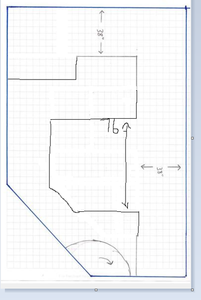
-Some updated measurements:

The shorter long wall is 135”

The longer long wall is 202”

The window wall is 137”

The door section of wall is 61” from door frame to corner of  shorter long wall.

The last section of wall is from door frame to corner of longer long wall. This section of wall is not angled, it is flat and perpendicular to the window wall. This piece is 70”

The only section that is angled is the wall with the door in it.

Height of the knee wall is 44”

Height to bottom of window sash is 34”

Thank you again for all the help. 

Just a quick back story. All of my track, and most of my trains came to me from my Father. They were his and my Uncles when they were kids in the 50’s. My Grandfather who I was very close with bought most of these train sets for them and spent hours playing with them with the kids. My Grandfather, and Uncle have both since passed. My Dad is 71, and I would like him to see his trains running once again before his health deteriorates. I now have children of my own 4 and 7, and would like to pass on this Lionel tradition.

Thank you again for your help. I’m currently cleaning all of their old track and will get a track count for you. I figured I could always buy more if I ran out. Thanks again

Welcome to the forum. Lot's of great talent and advice to be found here. I agree with Tom and Carl, an around the room "folded dog bone" style layout would work best. The head room along the wall is poor due to the roof line so better to place the trains there. I peninsula in the center would make for a great yard for switching trains.

Think about how you want to operate your trains- do you like to do a lot of switching or loop running.

If you want operating accessories watch the size of them. They take up a lot of real estate.

Try and use larger radius curves (054 min), as this will allow longer trains to negotiate curves easily.

How many trains do you want to run simultaneously?

You've come to the right place for help.

Bob

The whole room may be too much blue. Paint it any color that you like.

At the top of the forum, in the blue menu bar, you will see a search button.

Search attic layout a look at some of posts. That will give you some ideas of how other forum members utilize the space.

I think you'll need a fan at times. You can always get some different LED bulbs in different colors (2700k, 3200k, 5000k) to change the look. it should be ok for what you want to do and keep the costs down.

Thanks for the measurements. 34" isn't too low for a deck height - set up something flat that high and see how you like it. Avoiding going around the windows over the sill will make the build easier. That will give you 8"-10" on the sides of vertical space for buildings flats or painted scenery.

I'll set up the walls in my software and a beginning table shape to start and make them 30" wide, except for the ends near the door. 24"may work for you and it will make better use of sheet material. Cut a piece of cardboard and lay four lines of straight and an accessory or building, maybe a switch. Mock up what can fit for the long runs. You may be surprised with 24".

keeps things simple now to get something up and running. That will be enough of a task.

I can offer you a suggestion you may want to consider for your walls and ceiling. How eager you are to wanting the walls and ceiling painted would be a factor.

Using a roller, I gave the whole room a basecoat of a not-too-bright off-white; then, I painted the blue, using a brush, with my attitude relaxed, bit by bit. When I came to a spot where I thought a cloud might be happy, I left that area unpainted in blue, leaving it white; thus, having more of a creative experience than a chore. IMG_7634orig

The gradual process turned out to be fun. So, all the clouds you see here were not painted atop the blue sky. Rather, the blue was painted up to where I imagined clouds would be, letting the clouds take shape in front of me.

IMG_9208

photo 2x_edited-1

gift

parsonage [4)b

And of course I realized that if I wanted parts of the sky to be a little more stormy, I could take a bit of gray and shade/feather the bottoms in anytime I wanted.

Attachments

Images (5)
  • IMG_9208
  • IMG_7634orig
  • photo 2x_edited-1
  • gift
  • parsonage (4)b
Last edited by Moonson

Those are all amazing recommendations, thank you, thank you.

I checked the power today and all four outlets are hot and non switched. I think the whole attic is on one breaker.

I was thinking of making the benchwork wider, just using 4x8 sheets around the perimeter. Is 48” too deep to use for the top of the benchwork? That would leave me with 3’ in the middle to move around between the two sections. 

I would like a good mix of loop running and switching, with emphasis on loop running. I would like to run three trains at once, with a trolly/gang car line. I mainly will be using the sidings for storage of cars and engines. The few operating accessories I have could be on their own siding.

I bought some paint today and will get to work with the roller and brush.

Thank you again for the help.

Joe

Asymair95 posted:

I was thinking of making the benchwork wider, just using 4x8 sheets around the perimeter. Is 48” too deep to use for the top of the benchwork?

Height to bottom of window sash is 34”

Joe

If you build 32" tall bench work (same as I have in my attic layout), 42" wide is doable. I would not suggest going 48". FWIW, you can get under 32" bench work, but it is not fun. I'm 6'2" and can barely sit up under the layout. If I could have built it @34", I would have.

Last edited by Gilly@N&W

I was doing some mock up today and discovered what you are talking about. 48” is difficult to reach across for someone my height 5’9”. I am going with 34” on the height. 

I painted all the baseboard and doorway trim yesterday. This week will be the blue on the walls/clouds, and buying wood for the benchwork. 

Every night after everyone is in bed I clean 10 pieces of track. I have already cleaned, repaired, and tested all the switches. 

Interesting perspective on too low. My issue was it being seen while lounging on a sofa. 30" would have been nice I think, but before I ever take some off the legs I have something new to measure; the melon to joist clearance.

I'd want at least enough at 40" or 50" to fit an 0-36 or 0-48 line in. I know your focus is postwar, but there are just too many tempting engines that need something bigger than 0-31. You can't even run an old Berk, FM-TM, GG-1 etc on the 0-27, the 0-31 would be pushing it slightly.

A few comments on the comments.

Running a 726 Berkshire - I've run mine witht Irvingtom, Manhattan and Madison on my O-31 test loop with no problems, but it looks ridiculous.  You need two inches clearnace from the third rail on the outside of the curve.  Consider using O-56 on the outer loop, O-31 on the inner and something between on the middle.

The GG1 on O-31 is fine, the articulated chassis has four short segments.

Consider running all the way raound the room and having a lift bridge at the doorway.  It's not difficult and would give you about 50 foot long loops with no worries about the kind of crowding you'd have at the end of a dogbone.  I've built two of them, on curves.  I'll take some photos and post them tomorrow or Tuesday.  

I have solved all of the problems of maintaining alignment and electrical continuity.  Maybe I should write an article about building drawbridges.

In regard to accessories, If you want to be able to use the 97 coal elevator or 164 log loader, you need two tracks 15 inches apart.  That's an exact fit for a layout using  022 switches.  Consider this lyard diagram with a reverse curve between A and c and an 022 at B.  Tracks 1 and 2 will be 15 inches apart and the 97 0r 164 will fit perfectly.

1_____A

              \C______B______

2_____________  /

Some answers to concerns posted above.

I don’t want to use a wider radius track than the o31 I currently have. Part of the reason for building this layout is the nostalgia of running trains on track that was used by my Grandpa, Uncle, and Dad. This is why I’m going through all the trouble of cleaning the old track. I’ve seen videos of the wider radius track, looks great though. I have more o27 than I have o31 though.

I do have a few engines that will require the o31 track. There is a GG1 and Southern F3 that need the wider radius. Most everything else is o27 friendly.

I’m using 3m pads to clean the track, followed by a wipe down with wd40. The oil will be removed before running.

I was thinking about adding a complete loop around the room. The door to the room opens into the room though and would hit the benchwork. 

I don’t have either of those accessories. The only one left is the 364 log loader. All the other ones were sold several years ago when we fell on hard times

I would like to buy back some of the accessories we sold during that time. I will have to get a list together.


 Im not even addressing overhang looks, just versatility and my own regrets.

I only have a few modern pieces, and no huge desire for more, and defiantly not huge steam like a Big Boy, etc.; but already know two of my "new" medium-large choices would be no-go due to curve limits.  I have "all three" old track types in seperate loops on at ground level, and one more elevated 0-27 all on a 4.5x9 for a deep dish spaghetti bowl. Most of old the 0-27 and some old Super O (0-36) is there for much the same reason, "family track". but a larger loop still could have been worked in, and been a touch nicer, allowed bigger locos and/or allow more "scale" loco choices as even small ones are going to have greater restrictions in curves.

   Wanting to run fat wheel tin plate and also run smaller wheel flanges on the squared Super O rails, had me glad I had squared tube at least, but I was also removing the Super O switches a year or so after the install, to pass fat wheels and shoes by too.. sigh. I was aware and warned too; hindsight is a bit... ...too late.

Much of my being satisfied with old track went out the window the first time I added and used a new 3' section. On my ceiling layout, much of the track got soldered together to kill off pin issues as they occured. Another $40 in new track would have paid for itself easy vs repair times, even at only $5 an hour, plus lost performance, plus pita...

...just sayin', new metal is awsome & think about future possibilities


ASYMAIR95,

The room looks good.

Did you ever determine if the room is on its' on breaker?

You have assessed the infrastructure concerns. Identify the wall stud spacing now to the build easier when start.

I see that your are thinking of a wide table of about 42". View some of the photos that Dewey and others posted of their attic layouts. I don't think it's really necessary to have a table that wide when doing an around the room. You can create a peninsula, say for a yard or engine service area (as others have suggested) if you want one at a later time.

Around the room employs a different point of view or visual perspective to work with than a table layout. using the lower table height will permit building flats and scenic items along remaining vertical on the knee wall sides of the room. ~ 8" I believe, from your measurements.

You could save a lot of time using Evapo-Rust on the track. True value and auto stores should have the gallon. It will clean everything off and not harm the insulating paper. Soak, rinse with water, let dry, done.

Thinking about a track plan, I went back and viewed the layout that posted the link to on YouTube. The big difference with what you can do using an around the room is yours will be a stretched or expanded version. You will be able to have scenic areas separated. City, suburbs, woods, fields, hills, mountains. Perhaps traveling from one city to another. You could have a pseudo logging scene and the log loader and then travel to the other side to a sawmill/lumber yard scene.

Anyway, even if it's not deeply developed, having a reason for a train to run around adds to the viewing enjoyment.

Also, don't let the door stop you from thinking about going completely around the room. A lift out is not difficult to build. It's like a removable bridge. The track plan on the ends could designed now to permit changing the route or adding the change to a line in the future. (back to keep it simple and get trains running now)

Thanks for sharing your build project. It helps others and anyone with a layout will admit that this is a fun part process.

Here’s an idea for a layout that would give the maximum length of around the wall run with an allowance for the swing of the door.  The area behind the door could be for stub sidings.  I’m assuming a centered three foot door opening.

 I made a few assumptions about distance constraints.  I’m 5-10, and my greatest reach to set a train back on the track is about 33 inches,  given  a three foot high table.  That means a 3’ wide table. 

The sketch is based on  a continuous outside loop with a drawbridge or lift out section at the door.  It might be easier to have it be a hinged drop-down.  The two inner tracks could continue across the doorway on a 15 to 20 inch wide bridge. 

 Alternatively, the two inner tracks could converge with the outer track to cross the bridge, but then when running three trains, you’d need some traffic  control.  Of course that wouldn’t work if you want to start three trains and let them run.

 Did  I saw you mention that most of your equipment could run on  O-27 ?  With O-31 on the outer loop and O-27 on the inner, there are a lot of options to cross the doorway. 

 You didn’t say whether you must have a way to reverse trains.  There would be room for two loops at the window end of the room.

 The upper left hand corner shows space for a coal elevator and log loader.  You would have to close the door for access there.

 If you want to pursue the idea of a bridge across the doorway, I’d be glad to sketch a few specific possibilities and give you some rough specs for a drop-down section.

 Now I’m asking myself why am I doing this.  I think it’s because I enjoy working out layout problems but don’t have the room to build what I design.  I’ve designed much of the track layout on a famous HO model railroad club but don’t have the skills for actually building the track.  So I’m glad to do anything I can to help with  design .

 attic layoutMalcolm Laughlin

Attachments

Images (1)
  • attic layout

Today I went to Lowe’s and started purchasing lumber and supplies. 

5 sheets osb

10 2x4 studs for legs

20 1x4 for the frame.

paint

drywall mud

14ga wire red, black, grey

wire taps

glue

screws

foam

And some other things I can’t remember right now

C534F412-480A-4E43-825C-95CB0C0F4378

Mlaughlin, I’m thinking to start I would like to stick with a simple horse shoe design. Later I could possibly add on and do the lift gate. Your layout plan looks nice though. 

Moonman, I’m trying to picture a thinner bench top with an Island. Are you saying the peninsula would come out from the window area? This would make three long table tops, but just not as wide? How would I run multiple trains on a layout like this? If I did 32” wide I could run an outside loop of o31 and an inside of o27, but I’m not sure it would leave much room for sidings, accessories, and buildings.

The attic is on one breaker. There really is nothing drawing much power up there. Just a tv that doesn’t get used.

Thanks for the tip on evaporust, will give it a try.

Will check on the stud spacing. Will we be fastening the bench to the wall?

I looked up homasote at Home Depot and it is very expensive. I’m going to go with some cork roadbed from Midwest cork and paint/ballast it.

Attachments

Images (1)
  • C534F412-480A-4E43-825C-95CB0C0F4378

With kids aged 4 and 7 you are limited in the depth of the layout.  I would suggest no more than 2 feet. 

I would set the height at no more than 30 inches so the youngest can see and operated trains without needing a stool.

You need to have two mainlines (i.e., to kids) that will be operated (read that as race) trains independently,  

Add sidings and passing tracks along the inside edge for operating accessories.  They will need to be in easy reach of the youngest.

Any manual switch will also need to be within reach.

Keep scenery to a minimum.  It will just get in they way.  A few Plastiville buildings with a farm and a road with cars would good.

In a few years you'll be building a new layout with a pair of older kids.  From age 6 to 18 we had 6 different or "enhanced" layouts.  The first was 9' by 5', and the last was 16' by 11'.  Aren't full basements wonderful?

Jan

Last edited by Jan

ASYMAIR95,

You are moving right along - so, here it is - I was going to suggest a table build style borrowing elements from L-Girder construction.

Use pylons for wall supports and L-girders without joists for mounting the deck. This keeps everything open under the table, permits standing right up to the edge, and provides a thin edge for perhaps a hardboard or Masonite fascia.

I'll attach some photos of some examples of the elements below. I would have sent this stuff to you if you had an email in your profile.

Notice the spacer board on the wall to match the thickness of the baseboard that provides and even mounting surface.

The width of the L-girders only has to get within about 10" of the end of 3/4" deck material. Therefore the table width determines the length of the top rail.

The deck material is fastened from the bottom through the top of the L-girder. Drill a hole beforehand. Then, the top surface is smooth.

Pull the wire runs before installing the decking. Sounds like you've intended on doing that.

What do you think about this style? 


Attachments

Images (4)
  • L-Girder Wall pylons
  • L-girders no risers
  • Wall brackets
  • braces on L-Girders
mlaughlinnyc posted:

Here’s an idea for a layout that would give the maximum length of around the wall run with an allowance for the swing of the door.  The area behind the door could be for stub sidings.  I’m assuming a centered three foot door opening.

 I made a few assumptions about distance constraints.  I’m 5-10, and my greatest reach to set a train back on the track is about 33 inches,  given  a three foot high table.  That means a 3’ wide table. 

The sketch is based on  a continuous outside loop with a drawbridge or lift out section at the door.  It might be easier to have it be a hinged drop-down.  The two inner tracks could continue across the doorway on a 15 to 20 inch wide bridge. 

 Alternatively, the two inner tracks could converge with the outer track to cross the bridge, but then when running three trains, you’d need some traffic  control.  Of course that wouldn’t work if you want to start three trains and let them run.

 Did  I saw you mention that most of your equipment could run on  O-27 ?  With O-31 on the outer loop and O-27 on the inner, there are a lot of options to cross the doorway. 

 You didn’t say whether you must have a way to reverse trains.  There would be room for two loops at the window end of the room.

 The upper left hand corner shows space for a coal elevator and log loader.  You would have to close the door for access there.

 If you want to pursue the idea of a bridge across the doorway, I’d be glad to sketch a few specific possibilities and give you some rough specs for a drop-down section.

 Now I’m asking myself why am I doing this.  I think it’s because I enjoy working out layout problems but don’t have the room to build what I design.  I’ve designed much of the track layout on a famous HO model railroad club but don’t have the skills for actually building the track.  So I’m glad to do anything I can to help with  design .

 Malcolm Laughlin

Malcolm,

I like this design with branch lines and a mainline. He is going more the for '50's style and running his family trains. A difference with O gauge operators is that many prefer display type to operational running, meaning that multiple trains can run simultaneously unattended.

Here is Asymair95's room. The grid is 6". I am assuming a 30" door.

He will be running an O31 loop and an O27 track loop.

See what comes to mind. We'll see what he has for inventory and switches. Out and back with an r-loop at each side near the door, a continuous loop, ?

perhaps a few spurs for a yard to park some engines with kill switches. Conventional transformer controlled operation.

Attachments

Images (1)
  • Asymair95_Room
Last edited by Moonman

Was going to get going on the construction today, but I have a kid home from school today with the stomach bug...up vomiting all night long, fun.

Moonman, that benchwork is beautiful, but I’m not crazy about the idea of putting holes in the wall like that. I was thinking of just doing a simple table type with a rectangle frame, and 2x4 legs with everything screwed together for easy disassembly if the need arises.

Jan, my kids will be supervised at all times when operating the layout. These trains are family heirlooms and my kids are...less than gentle with their toys. I guess they are typical little boys.

Asymair95 posted:

Was going to get going on the construction today, but I have a kid home from school today with the stomach bug...up vomiting all night long, fun.

Moonman, that benchwork is beautiful, but I’m not crazy about the idea of putting holes in the wall like that. I was thinking of just doing a simple table type with a rectangle frame, and 2x4 legs with everything screwed together for easy disassembly if the need arises.

Jan, my kids will be supervised at all times when operating the layout. These trains are family heirlooms and my kids are...less than gentle with their toys. I guess they are typical little boys.

I get the grandkids when that happens.

The holes are no big deal - you just did a kitchen. The pylons can be 8' apart.

Cut a bunch of pieces and assemble them. Deck screws and drill and screw gun. They dissemble just as easily. A screw gun and a sawzall can do a lot of work quickly when it's demolition time.

The big advantage is the open area with no legs underneath.

It's your Benchwork, do it as you please. Just putting it out there.

Help your child feel better, trains tables are a low priority. That was not a fun night.

Thank you for the tips guys. 

Mlaughlin, I believe I have one of those switches. I also have a few Lionel push button types.

Rsjb, that is a nice layout you have there. No toggles for me on the switches, I have the original switch boxes with lights in them for my 1121 switches. I might use a toggle like that for lighting though. I would like some lights for night ops. I really like your control panel, very neat looking.

  From childhood experience, I have to say 42" on height is way too high for kids. That's a adults layouts height, likely a tall one too... imo anyhow. The repercussions will be a need for stools to stand on, and a box of Band-Aids for when they fall off the stools, which in thier excitement WILL happen, more than once or twice too. 

  My elders were always one step ahead of the game.Though the cast train was waiting for me to be born, Gramps also purposly bought me some cheap Scouts for me to destroy when unattended, so I felt the loss of a broken toy and learned to mind my things better. Cast steamers with spur gears vs worms were also chosen because I couldn't do much harm to them; the back up   Only one of his Grandkids got a really nice FM diesel when young "the most careful one" (a girl , who still likes her trains; but she never did get "GG-1 certified" by Gramps. An aunt and I were the only ones he trusted running GG-1s

  I was also included in every build and repair I'd sit still for; which was a lot. The interest was used as a regular incentive to "act right" too. Encouraged behaviors and personal goals reached, often got me some new unannounced "freedom" on Gramps layout, maybe a surprise of a new car or accessory, etc.

  Transformer breakers were tested often and I was shown red hot wires and meltdowns too, so I understood the danger of neglecting a short pretty well. Once you get that first stove blister, you tend to be more careful with "hot"   

  By about second grade I was phasing transformers with phone help and could pretty much do as I pleased with them all. Not all kids mature that soon, but the point is; don't underestimate them. If they do consistantly show the ability to be careful, act "right", and make good choices in general, you should reward it, and toy trains privileges can be an excellent motivation.


mlaughlinnyc posted:

That's my kind of railroad - all track and trains, never mind the scenery. I'm for modeling the railroad to the edge of the roadbed.

I'm in favor of that right-up-front track system, too, but I have managed to squeeze in a little bit of scenery, as well, just to add to the moment when the trains are nearing or passing by, right at the edge. I wanted guests and myself asIMG_1087allPING close to the trains as possible.

IMG_0113

..reach-in and touch them close...

IMG_0068b

FrankM, MoonTownship, USA

Attachments

Images (4)
  • IMG_1087
  • allPING
  • IMG_0113
  • IMG_0068b
Last edited by Moonson

  I model to the edge too, but if I were to have kids running regularly, to stop dives from accidental or careless highspeed rollovers, I'd have a good sized space at the curves bordering the edges, or put a decent guard rail up.

Leaving some space of a few inches away on any portion facing you allows you to lean over to grab this or that while a train is still running. Too close, and the train will likely clip your body as it passes..... unless maybe your real skinny and shirtless  

Reaching over without leaning is very uncomfortable; an unatural postion.

Asymair95 posted:

Wow...that is amazing! Beautiful.

Thank You, very much!

A little trick I use when running the 10 trains (using TMCC) and one trolley is that when a train, steam locomotive or diesel, approaches where a person, adult or child, is standing, usually looking and gesturing, I sound the horns long and steady, warning of their approach, as well as adding a little 'theater" to the moment. Everybody gets the message. I have not had a single locomotive or car knocked off its tracks, not even bumped, since the first layout of 1995.

IMG_0852

looking toward neck

I will, however, at times, stop a train right in front of a guest if it seems  they'd like to give it a touch or a little caress, which has sometimes been the case. I liked everything right up front and available, to scrutiny and touch, as much as possible.

IMG_8599

middle_12

FrankM

P.S. I want the layout to give people joy. I am not touch-me-not about the layout or its trains at all. I like the smiles the best. Beyond that, I do not spend energy worrying about accidents.

Attachments

Images (4)
  • IMG_0852
  • IMG_8599
  • looking toward neck
  • middle_12
Last edited by Moonson

Ok,

The only concern that I have is what happens when you stand in the aisle from the center to the windows? Does the slope of the ceiling force you to bend over?

I flipped your photo and used it as a background image in SCARM and tried to recreate the tables. The walls are the blue polygon outline.

Then, using circles and squares, (well, only circles), placed O31 circles to check for fitment.

You can put rectangle footprints in for accessories and buildings, then work the track around those.

The yard could be a little tricky on the triangle. I may try a wye on the center island and perhaps the yard in there.

Then, work the O27 line in. 

SCARM now has 6"(imperial grid) option. If you have 5", it's an older beta version.

Attachments

Images (1)
  • Asymair95_Room_Table_2

That table design gives me interesting ideas.  Let's check your specs before I play more with this.

1. You want to run three trains independently.  That means three loops.  Is it OK if loops cross w/ 45 or 90 degree crossings ?

2.  Does on O-31 and two O-27 loops meet the spec ?

3. should there be crossovers so taht all loops connect ?

4. do you want to have a wye or reverse loop ?

5. How do you feel about O-31/O-27 transition sections.

Malcol;m 
LAughlin


Just a thought, instead of 2 small peninsulas, why not one wide peninsula that would allow for a great variety of track configurations.  The two small peninsulas (and walk ways) take up a lot of space, and don't give you many track options.

If the one large peninsula (76in below, but could be shortened) is slid toward the door, it would also allow for a bump out in the top section to allow for more space for a reverse loop, wider radius track, scenery, accessories, etc.  

There is a slight reach issue on the right side of the big peninsula, for my money, in that space, I'd be ok sacrificing the reach there to gain a large area as shown below.  Yard tracks/engine house, etc could be down by the door.

Just throwing some ideas out there...

Thanks. 


Attachments

Images (1)
  • mceclip0

2018_01_08_10_53_40_Help_me_design_an_attic_layout_O_Gauge_Railroading_On_Line_Forum

Here is an idea - 

I inserted a lionel dealer display plan for a D-264 onto the peninsula.  Added some track options.  You can have 4 trains running on independent loops.  Has some crossings for interest. Space for industry sidings. A yard for train building. 

Granted, my "work of art" above is not to scale, so my track fitting is just a guess.   Just sending an idea out there to see if this is going down the right track for your end goal or not.

 You could add access below the mountain on the D-264 to gain reach access if needed

D-264 below:

Image result for lionel d-264


Attachments

Images (1)
  • 2018_01_08_10_53_40_Help_me_design_an_attic_layout_O_Gauge_Railroading_On_Line_Forum
Last edited by JD2035RR
Moonman posted:...

You can put rectangle footprints in for accessories and buildings, then work the track around those.

I found that system to be very helpful, often...2This corner trailer- park is an example. The Masonite baseplate was measured and configured and then crafted off the layout, once the track was configured for this wide curve, and then, screwed in place. You may be able to see the Masonite baseplate's edge temporarily exposed here and there..BB

Across the three-mainline tracks at this corner curve is this neighborhood, planned and crafted using the same procedure = baseplate configured in; then, the craftwork completed upon each baseplate, and each individual project affixed into place...

IMG_4345

IMG_4346

IMG_4428

IMG_4422

IMG_4425

The super-advantage to using baseplates everywhere I can is that if I change my mind about emplacement of a vignette, all I have to do is unscrew it (if it is screwed down) and lift it out, with ZERO loss of ingredients or damage to the structures

FrankM, Moon's son..

Attachments

Images (7)
  • 2
  • BB
  • IMG_4345
  • IMG_4346
  • IMG_4422
  • IMG_4425
  • IMG_4428
Last edited by Moonson

JD2035,

I was originally going to have one large peninsula in the middle instead of two smaller ones. I was worried about not being able to reach things though. What do guys typically do on larger areas of real estate like that? I really like your layout ideas though, I would much prefer something along those lines. It adds lots of interest, but still leaves room for accessories. I don’t have that many switches at the moment though, and that plan has lots of them...lol. Here is a pic of what I currently have:

4A470564-8232-4627-BFA0-A3B0CFCF2A50

7 o27 switches, 4 o31 switches and one crossover that I believe is for o31. I have tons of track, but definite have twice as much o27 as I do o31.

Moonman,

Thank you for that plan. I made the aisle 3’ from the wall so I wouldn’t bump my head on the ceiling. After seeing JD2035 larger peninsula idea, I’m leaning more towards that.  How large should I go? I can fit a full 8’ in there and still have a 2’ aisle on the door side and window side.

Mlaughlin,

Yes, all those things sound great. Would the crossover require one train to wait while one passed? My engines aren’t the most reliable, I wouldn’t trust them to start back up again after a mementary stop. What is a o27/o31 transition? Is this a piece I would need to fabricate?

Thank you for all the ideas and help. I got a big box from woodlandscenics today. I’ve also been busy on eBay replacing all the accessories we had to sell a few years back. Still breaks my heart to this day. So far I have scored a Lionel 24” metal bridge, gateman, and switch tower.

What is everyone’s thoughts on the Midwest cork roadbed?

Attachments

Images (1)
  • 4A470564-8232-4627-BFA0-A3B0CFCF2A50

In my sketch, without the yard, there are six LH switches, six RH switches, one 45 degree crossover, and two 90 degree crossovers.  I believe the D-264 is approximately 9x5, but that is using Super 0 track which I believe is 0-36.  You would have to modify the plan for 027-031, but you might still need the same amount of space to ensure that the grade isn't too steep.

I think the peninsula should be 5-6 ft wide (allowing 2.5 - 3.0ft reach from either side), depending on the elements you want to fit inside the space.

There is a buy/sell forum here, I have had good luck acquiring additional pieces I needed for reasonable prices from people who enjoy helping another guy out.  With this size of a layout, you may want to get a bunch of 022 O gauge switches that you can supply with fixed voltage and switch remotely.

Well, you have a switch shortage in O31. Anyhow, we can work what you have.

I just feel like the O27 looks to snappy in the curves. It's a little more delicate to work with. The lower rail height looks good.

I would say lean over a table or something and see where the reach is comfortable to fiddle with a train.

I like the 2 peninsulas  for boys. They can be in different locations and operating different accessories or just having their own viewing spot.

So, the main loop looks like it will be in O27 and the secondary loop in O31. We need some spurs for accessories.

Also, consider that you can shape the deck in curves and still have the rectangular/angles framing underneath. Just allow for enough overhang to cut the curve with a jigsaw. Something about corners bugs me.

let us know what you decide for the peninsulas/width.


After leaning over some correct height tables, I would like to make the peninsula 7’ across. I can fit 8’ but it’s not possible for me to reach that far. The depth of the peninsula can stay the same as it was with the original plan. It will be tough to reach the area behind the peninsula, but I will just leave that somewhat barren, or put a farm there.

Thanks for the heads up on the buy sell area on the forum. Will stop by and put some requests in.

i will definitely leave some room around the outside of the table for jigsaw trimming.


ASYMAIR95, if you close the attic door and notice the room is getting cold, you may have to put a few 1"or 2" dia. holes in the layout against the wall above the baseboard radiator. Sorry I just started following your project this morning. I would have suggested leaving a gap between the wall and the layout above that radiator. Radiators have to move the air in the room through them, by means of convection, as quickly as possible to heat the room at the same speed as the room with the thermostat in it. If you don't allow for the heat to raise, the heat will be trapped under the layout. You may have to put a small fan under there to help move the heat into the room. Which ever you do, it will help to keep the tracks from expanding and contracting over the radiator. Also, if you hang curtains off the front of the layout, keep a gap between the floor and the curtains so that the cold air in the room can move to the radiator.

Last edited by Dave Zucal

Dave, I don’t run the heat much up there to save heating oil. The rising heat from downstairs keeps it pretty warm up there.

2035, I thought about putting a hatch in, but it seems like a lot of work. I’m thinking I’ll just put some plasticville houses in that area to take up space. I’ll keep the track shenanigan to a minimum out there too.

The first coat of paint last night.

888943C0-F75A-4260-8104-E5FCFDBFDBF9

91B926E2-8558-4692-8D89-849D235237B2

Watching the birds at the feeder from the train room

9250A288-03C5-4024-8AF7-242EF90D1035

Attachments

Images (3)
  • 888943C0-F75A-4260-8104-E5FCFDBFDBF9
  • 91B926E2-8558-4692-8D89-849D235237B2
  • 9250A288-03C5-4024-8AF7-242EF90D1035

I throw an idea out there for you.  Sorry I don't do the track planning software.  I included a hatch (green square) as part of the plan.  Redline is the trolley line going through the plasticville city.  Not sure how you feel about a lift bridge/swing bridge/duckunder, but that aisle is begging for a double bridge!  

What elements do you like and dislike in the below idea?


Attachments

Images (1)
  • mceclip0
Last edited by JD2035RR
JD2035RR posted:

I throw an idea out there for you.  Sorry I don't do the track planning software.  I included a hatch (green square) as part of the plan.  Redline is the trolley line going through the plasticville city.  Not surehow you feel about a lift bridge/swing bridge/duckunder, but that aisle is begging for a double bridge!  ..

The only advice I could offer you regarding lift/swing/duckunder bridges on layouts is that I have noticed many postings, here and on other forums, stating that the hobbyists got real tired of them fast, eventually even removing them, in several cases. I wouldn't even consider having one.

As evidence, if you take notice of the line of Second-level bridges and arch-unders in the foreground of this mid-section to my layout...8...I had considered having a duckunder there, but decided against it,  knowing we would have plenty of company and that the chances of somebody, especially children and older, less flexible adults, bumping heads into such a structure, I decided it was best to have guests able to walk right up to the bridges and peer over and beyond them into the valley beyond, and up into the hills of the Second and Third levels beyond, at 14' distance away, approx....IMG_0861edx 

Of course, if having a moveable bridge arrangement interests and amuses you, then doing what you feel would be enjoyable for you, of course, is a big part of the adventure of creating a layout.

FrankM

Attachments

Images (2)
  • 8
  • IMG_0861edx
Last edited by Moonson

Good start with base color - now use other earth colors and patchy areas of a second coat of that color. may want to wait until you get a track plan.

Do you have any half-straights and half-curves in O27?

Oh, no one answered your question about the Midwest cork - if it is in your budget - use it. You will have a very quiet layout and make the experience more enjoyable.  Painting the cork with a single coat of gray will look like ballast.

Last edited by Moonman

Moonman,

I don’t have any half sections. I was going to buy several from tin man, as well as some insulated sections, and several power tap sections. 

I caulked the seams last night and put another coat of green on. Going to fabricate and paint a perimeter around the control panel tonight. Need to finish up cleaning the rest of my track and settle on a track plan. 

I’m thinking of putting push button switches around the perimeter of the layout near different operating accessories and lights for the kids to press. I was going to put them all on the control panel, but thought it would be more fun for the kids to be able to press various buttons throughout the layout and operate things. 

Anyone have a go to switch they use for something like that? 

Ok,

I am working on some track ideas.  just trying to get to know your inventory in O27. You can always cut the long straights, but the curves are a little tricky. It's very limiting to work with a full curve.

Door bell buttons are the simplest for momentary on.  There are big colored and lighted ones, but keep it simple. They like the doorbell buttons with a label.


Attachments

Images (2)
  • Asymair95_Table_as_Built_Track_Idea
  • Asymair95_Table_as_Built_Track_Idea_3D
Files (1)

NEW-HAPP-ARCADE-BUTTONS-ANY-COLOR-OR-PLR-MAME-MULTICADE

https://www.ebay.com/itm/NEW-H...p2060353.m1438.l2649

I bought these.  They come with small micro switches that are easy to wire.  I liked the look and will take a lot of abuse being arcade buttons.  They also have lighted ones.

Do you plan to run your trains conventionally? TMCC/Legacy? DCS? Lionchief (+)/RC?


Attachments

Images (1)
  • mceclip0
Last edited by JD2035RR

Moonman,

thank you, that looks like a good start. I like the cross section of track. I can always buy more track, or specialty pieces if need be. I was thinking of getting another four way, and an X section also. Looking at an auction for four more switches too. I just came in from cleaning the last of my o27 track. Tomorrow I will start on the o31. It should go quick as it is in much better shape.

2035,

Thank you for the button link. My only concern with those is they look like I have to drill a fairly large hole to mount them. I would like to mount them on the facia board around the circumference of the layout. This is also a support board though and is relatively weak being only 1x3 ferring strip. I’m afraid putting a big hole like that through it will weaken it too much. The door bell idea sounds good though. I can just screw it to the outside and drill a small hole for wires to pass through.

This will be a conventional powered layout. I have a zw and a few older Lionel transformers for lighting, accessories, and powering sidings and such.

Do you guys like the woodland scenics incline/decline risers for elevating the track? Good bad?

JD2035RR posted:

NEW-HAPP-ARCADE-BUTTONS-ANY-COLOR-OR-PLR-MAME-MULTICADE

https://www.ebay.com/itm/NEW-H...p2060353.m1438.l2649

I bought these.  They come with small micro switches that are easy to wire.  I liked the look and will take a lot of abuse being arcade buttons.  They also have lighted ones.

Do you plan to run your trains conventionally? TMCC/Legacy? DCS? Lionchief (+)/RC?


JD2035RR - Nice looking button. What I cannot find is the electrical specifications for the switch. I do not know the standards for arcade electronics. Is the voltage/amperage stamped on the bottom of the microswitch?  Do you know from any other source?

Asymair95 - It's an 1 1/8" hole that is needed. It won't hurt the strength as you won't be loading the weight to extremes. A wobbly 1" speed bore and your done. They are cool looking.

Last edited by Moonman

I would use graduated trestles with a roadbed track, so that if I were not happy with the track plan or would get bored with it, it would be easier to make changes to the layout and try some new ideas. Once I felt I was happy with the layout after running it for some time, then I would plaster in some woodland scenic inclines. You can also look through an elevated trestle if it runs in the foreground of a layout. Plastered in elevated track is better in the background of a layout. A word of caution though, a layout can get very heavy. In a basement weight is not a problem. In an attic space, the weight and vibration can become an issue, for the ceiling in the room below it. If that room was meant to be a living space as part of the original building plan, it will have floor joist and support more weight then a room that was created later from an attic space on top of ceiling joist. If there is a supporting wall under an attic room, weight is not much of an issue.

new track ideas - fixed siding directions - 2 -O27 switches left - accessory sidings in - a passing siding -

added O track - whimsical, but will teach the boys switch control - non-derail will be helpful as they can run multiple routes by changing one switch

kept switches and sidings near the edge - that's where derails may happen and accessory operation may need assistance

added a couple of two curve tunnels - kids like to get at eye level and watch the train in the tunnel

you can decide how to deploy the two remaining switches - there is space for sidings

SCARM menu bar > Tools > Parts List will create that to compare to your inventory - an O27 cross, some O27 half straights and a cut track is all that is needed

Oh, I like the location of the control panel - good view of most of the layout without rubber necking

Try running the basic simulator to test for play value - it's cool in 3D


Attachments

Last edited by Moonman
Moonman posted:
JD2035RR posted:

NEW-HAPP-ARCADE-BUTTONS-ANY-COLOR-OR-PLR-MAME-MULTICADE

https://www.ebay.com/itm/NEW-H...p2060353.m1438.l2649

I bought these.  They come with small micro switches that are easy to wire.  I liked the look and will take a lot of abuse being arcade buttons.  They also have lighted ones.

Do you plan to run your trains conventionally? TMCC/Legacy? DCS? Lionchief (+)/RC?


JD2035RR - Nice looking button. What I cannot find is the electrical specifications for the switch. I do not know the standards for arcade electronics. Is the voltage/amperage stamped on the bottom of the microswitch?  Do you know from any other source?

Asymair95 - It's an 1 1/8" hole that is needed. It won't hurt the strength as you won't be loading the weight to extremes. A wobbly 1" speed bore and your done. They are cool looking.

That's a rather large hole to put in a 1" x 3" furring strip, which is not the best grade of lumber to start with.  If he is going with these switches, he would be better served to use a 1 1/8" hole saw.  It will give him a nice clean hole, eliminating the tarot on the back side of the board.  

I found these on Evilbay.  The require a half inch hole. Here's the link.

https://www.ebay.com/itm/New-5-PCS-Push-Power-Button-Green-16mm-Switch-Momentary-Squareness/302604396132?hash=item4674a0a664:g:zGAAAOSw38BaXZ-xbutton 1button 2

Attachments

Images (2)
  • button 1
  • button 2
Moonman posted:
JD2035RR posted:

NEW-HAPP-ARCADE-BUTTONS-ANY-COLOR-OR-PLR-MAME-MULTICADE

https://www.ebay.com/itm/NEW-H...p2060353.m1438.l2649

I bought these.  They come with small micro switches that are easy to wire.  I liked the look and will take a lot of abuse being arcade buttons.  They also have lighted ones.

Do you plan to run your trains conventionally? TMCC/Legacy? DCS? Lionchief (+)/RC?


JD2035RR - Nice looking button. What I cannot find is the electrical specifications for the switch. I do not know the standards for arcade electronics. Is the voltage/amperage stamped on the bottom of the microswitch?  Do you know from any other source?

Asymair95 - It's an 1 1/8" hole that is needed. It won't hurt the strength as you won't be loading the weight to extremes. A wobbly 1" speed bore and your done. They are cool looking.

The switch itself doesn't say. I emailed the eBay seller who said that the specs say 125ac and 15 amps. 

Asymair95 posted:

Thank you for the layout update, that looks nice. It will definitely give me a good start to get going.

The graduated trestle set is a good idea, I will look for some on eBay.

I will also look around on eBay for some buttons, and track cross overs. 

Thank you so much for the help and ideas.

I meant to say that the control panel location does not require rubber necking.

Here's what a #110 set would like with a 317 bridge along the long wall. Starts in the curve and ends in the opposite curve to allow for the bridge.

Asymair95_Layout_01.16.18_3D_Trestles

Attachments

Forum member RogerPete builds a Christmas Display each year. If you watch the table on the far wall in the video you can see what mottled paint turns out for the base.

He just used what they had at the historic group and it turned out well.

Just wanted to point out what you can achieve with some sloppy painting and nothing fancy.

I had to dig to find my bookmark for this post, hence the delay since the baseboard painting post.


Last edited by Moonman

Moonman,

I really like the trestle and bridge. I have a bridge already and will be looking for a trestle set soon. I would also like to add a girder bridge on a small rise, maybe an inch or two. Also purchased the Midwest cork roadbed.

Was thinking of adding an elevated trestle loop over the track on the big middle section where the 8 is. What do you think?

Asymair95 posted:

Moonman,

I really like the trestle and bridge. I have a bridge already and will be looking for a trestle set soon. I would also like to add a girder bridge on a small rise, maybe an inch or two. Also purchased the Midwest cork roadbed.

Was thinking of adding an elevated trestle loop over the track on the big middle section where the 8 is. What do you think?

That would depend on the boys. That would be too difficult of a train to play with for my grandson. He is 6.  he does well getting cars and engines railed on deck height, but sometimes will miss a truck.

I only coach them on their train table. What is on it is free game.

If you limit the voltage to the elevated train, it could be a no touch, run only line for them.

Well, you have the run under the window and along the short length wall to create a low rise up and down. 

Last edited by Moonman
Asymair95 posted:

https://www.ebay.com/itm/40pcs...p2057872.m2749.l2649

I found some switches I like. Think they will work fine for the kids to play with.

Did you notice that they are latching?  On will stay on until pressed again. Something will get cooked. Good switch for building lights on or off or motorized animated things, like lemax Ferris wheels and such, or the beacon tower, the radar tower.

We used the momentary switches on the museum layout with a relay. They can push and hold or continuous push, but it's only activated once until it cycles completely.

Those are good to have on hand.

You'll find with stuff for trains, that when you find something that you like for a purpose, you should get extras. You will want another one later.

Thank you for that trestle link. 

I did get the latching for lights and such. There are a few accessories I would like to run on those too. Need to get some momentary on buttons too for other things like you said.

I think the elevated trestle would be OK as long as it was a small motorized unit like the trolly or gang car. I wouldn’t let them put larger trains up there for safety reasons.

Last night I finished up cleaning all the o27 track and switches. Today I will start on the o31 stuff. Should go quick.

On my o42 switches the red and green lanterns lost their plastic colored lenses. I found them in the bottom of the box, but how do I get them back in? Crazy glue?

Thank you again.

The arcade buttons should not be latching.

Prefabbed metal reinforcement plates and button mounting L brackets are available through arcade suppliers. (my old suppler is out of businesses). (The hole is a bit large for easily drilling your own in metal)(the mounting brackets are usually used inside the game/vending cabnets for programing, etc.)

I can attest to duck unders and lifts getting old fast.  You'll end up ducking anyhow to avoid lifting, smashing fingers, running a train off a cliff, etc..

PITA enough to scrap the yard on a 15x30 oval for a dogbone.

If I did another out of necessity, the bridge (or hatch) would drop down vs lift. 

IMG_1544-001Congratulations on getting your benchwork roughed out.  As Frank (Moonman) suggested ease those sharp hurtful exterior corners before much railroad work is done. Also avoid a duckunder ( if considered) by installing a piano hinged drop section which you can disguise as a plate girder bridge. Jim Barrett did a video[#11) of "how to" as well as parts,etc. You will seriously regret a duckunder as others have said, yet it will provide much flexibility in track planning for longerIMG_1636IMG_1582-001100_1321100_1322 runs. My drop section pictured below  was built from Jim's long ago article in O-Gauge Magazine and is rescued from two of my former layouts.   

Attachments

Images (5)
  • IMG_1636
  • IMG_1582-001
  • 100_1321: Showing the simple mechanism and wiring to power bridge tracks
  • 100_1322: railpower wiring loop from main benchwork to bridge track
  • IMG_1544-001: Highway traffic along the rails.
Last edited by Dewey Trogdon

Answer to your thoughts about an elevated line - yes, if it has somewhere to go - two small hills do that with a station and a platform

You can cut your own support pylons from wood and paint them for a clean look

Asymair95_Layout_01.16.18_3D_Trestles_Elevated_Line

If you want some SCARM buildings to play with, search the net for SCARM Hi-Railers. Forum member John D. and his father own the site.

Save the file and open in a second instance of SCARM. Then copy and paste into the layout SCARM. Set the properties for height and such, rotate for position.

I also found the O27 bridge for the trestle run. The other was an O #317, which was too long. 

Attachments

Moonman posted:
JD2035RR posted:

It's amazing how you bring these things to life, Carl.  Great job!

Thank you. I give credit to others for creating the structures. They have some talent.

The 3D is really helpful to portray an idea.  

I've tried scarm on my home computer, and there's a bit of a learning curve.  You make it seem easy.

That looks great. Will post back when all my track is cleaned and ready for install. Any chance of two outside loops? Maybe one in o31 on the outside, and one in o27 on the inside? The village area looks great, I like the raised trestle, it’s really going to make it look nice. The bridge I have is a 314 I believe. Is it too big for this layout? Maybe I could just go up 3” instead of the full 4” to shorten the incline and decline run? 

Received my 128 operating newsstand  in the mail today. Of course it didn’t work...lol. Been futzing with it all night trying to get the spring tension, and coil air gap right. The problem I was having was the string kept jumping off the pulley. I ended up gluing a guide around the string to keep it from whipping so much and falling off. Works pretty good now. It’s slow, but dependable now.

Also received my operating baggage terminal today. It didn’t work either. That’s tomorrow’s project. It hums and vibrates a bit, but the carts don’t move very well. I adjusted the screws on the bottom, but that didn’t do much. 

Thank you again for the track plan, looks great. 

ASYMAIR95,

I would not put a double main. The track to scenery ration would go to high, the curves diameters are awkward to make interesting and overall would take away from your goal.

You will find that the accessories and buildings take a lot of real estate. Just start placing them on the table to see for yourself.

I like the full trestle set to put on show on that long wall. It's rather boring if you don't.

Post new topics on tuning these accessories. There is a wealth of experience and knowledge on how to make them work reliably. There is also, Olsen's, which has a library of service documents that sometimes have tuning and modification tips. Here is the 128 newsstand. The string coming off is due to too high of a voltage. You'll find that each accessory has a sweet spot for voltage. Many times you can videos on YouTube of them working.

For the newer accessories, viewing the Lionel parts diagram and getting assistance from forum members definitely helps.

Trees, you cannot have enough trees. Bottle brush trees work to get going and are relatively inexpensive.

Don't lose sight of your goal -get the heirloom trains up and running - keep it simple to accomplish it. You and the boys will want to build another one together.

here's the latest version of the layout. Added another siding to the O layout using one of the switches that you acquired.

The Rico station silhouetted against the window light would look nice. it is both freight and passenger.

Asymair95_Layout_01.19.18_3D


Attachments

Images (1)
  • Asymair95_Layout_01.19.18_3D
Files (1)

Looks great. Is there a go to place for cheap trees? I did some looking and they are pretty expensive.

Like that layout, think it will work great for the look I’m going for. I bought a 110 trestle set last night still in the original sealed bags. They are brown ones, but have all the required clips. Is there a trestle set that Lionel made that is just the raised sections, not the incline/decline? 

Thank you for the accessory tips. 

Asymair95 posted:

Looks great. Is there a go to place for cheap trees? I did some looking and they are pretty expensive.

Like that layout, think it will work great for the look I’m going for. I bought a 110 trestle set last night still in the original sealed bags. They are brown ones, but have all the required clips. Is there a trestle set that Lionel made that is just the raised sections, not the incline/decline? 

Thank you for the accessory tips. 

Cheap trees - If you are looking for evergreen, the best tip I have heard is to pick up an old artificial Christmas tree, and cut the branches into varying sizes of trees, and shape the needles accordingly.

The Lionel 111 trestle set is the elevated (all approximately 4 - 7/8 inches high I believe). However, you can certainly make your own out of 1x4s that could allow for greater clearance below.


That’s a great tip, will check out Craigslist for someone giving one away. The wife is going to love me. Every other day a new box is showing up. The only thing saving me from certain doom is the excitement from the kids when we open them...lol. She gives me this look like “You’re lucky...this time” because she can see how happy the kids are.

Trees - making them is craft the boys can do now - there are weeds that work well for arbors - get them gooey and sprinkle stuff on them - or dunk in a box-

There may still be some of the bare weed sticks in a field near you.

check out youtube for various techniques

I do mostly winter - so the frosted bottle brush trees can found for not a lot of money. I couldn't find any plain versions yet.

JD2035RR posted:
Asymair95 posted:

Looks great. Is there a go to place for cheap trees? I did some looking and they are pretty expensive.

Like that layout, think it will work great for the look I’m going for. I bought a 110 trestle set last night still in the original sealed bags. They are brown ones, but have all the required clips. Is there a trestle set that Lionel made that is just the raised sections, not the incline/decline? 

Thank you for the accessory tips. 

Cheap trees - If you are looking for evergreen, the best tip I have heard is to pick up an old artificial Christmas tree, and cut the branches into varying sizes of trees, and shape the needles accordingly.

The Lionel 111 trestle set is the elevated (all approximately 4 - 7/8 inches high I believe). However, you can certainly make your own out of 1x4s that could allow for greater clearance below.


I have the 111 set but only used it for the grades. I made my elevated posts out of 1" wood dowel. My only suggestion is to make them about 5 1/2". I made mine 5" and some newer stuff doesn't fit under my upper level.

2017-01-14 09.54.432017-05-06 08.55.36

Attachments

Images (2)
  • 2017-01-14 09.54.43
  • 2017-05-06 08.55.36
Asymair95 posted:

How many power taps (lockons) will a layout of this size need? 

Id say about every 3-4 ft.. Less if you use 3ft sections. I like to solder to the underside of tubular curves as being close to the feed in curves really helps steady the speed.

Also, I have a zw transformer, and four smaller individual transformers. How many will I need total to run sidings, lighting, accessories, and trains?

As many as you wish though the ZW alone could handle.a lot. BUT when using two or more transformers together they do need to be "phased". This is new and old types alike. The best video imo is on Youtube, search there for Phasing Lionel Transformers, and chose the one by Lionel.

Thank you again for helping a flailing newbie.

Our pleasure !


Asymair95 posted:

How many power taps (lockons) will a layout of this size need? 

The trains will tell you that - they will slow in areas - I would suggest to start with six for the O27 line - two on each side between the ends

two for the O31 - and one for the elevated

Also, I have a zw transformer, and four smaller individual transformers. How many will I need total to run sidings, lighting, accessories, and trains?

Again, it depends on the trains - Use a handle  of the ZW (A& D) for each main loop - use the accessory terminals B & C to group accessories by voltage 14v for switches and 12-14 volt for whatever likes that

use a smaller transformer for the elevated line and another smaller transformer as needed if an accessory likes a different voltage

Thank you again for helping a flailing newbie.

A Handy Reference is attached to reduce flailing - don't let the boys see that!


Attachments

Files (1)
Last edited by Moonman
RSJB18 posted:
JD2035RR posted:
Asymair95 posted:

Looks great. Is there a go to place for cheap trees? I did some looking and they are pretty expensive.

Like that layout, think it will work great for the look I’m going for. I bought a 110 trestle set last night still in the original sealed bags. They are brown ones, but have all the required clips. Is there a trestle set that Lionel made that is just the raised sections, not the incline/decline? 

Thank you for the accessory tips. 

Cheap trees - If you are looking for evergreen, the best tip I have heard is to pick up an old artificial Christmas tree, and cut the branches into varying sizes of trees, and shape the needles accordingly.

The Lionel 111 trestle set is the elevated (all approximately 4 - 7/8 inches high I believe). However, you can certainly make your own out of 1x4s that could allow for greater clearance below.


I have the 111 set but only used it for the grades. I made my elevated posts out of 1" wood dowel. My only suggestion is to make them about 5 1/2". I made mine 5" and some newer stuff doesn't fit under my upper level.

2017-01-14 09.54.432017-05-06 08.55.36

Is your tender on backwards?


I know this thread is a year old, but it took me that long to get back on track (Pun intended) to finish my layout. 

Just a quick refresher on last year’s events. I inherited my Grandfathers, Fathers, and Uncles trains. I am a hopelessly flailing newbie with zero train experience. I have been reading and watching videos over the past year trying to educate myself. I would like to build a layout for my two children and I to enjoy. More importantly, I would like my 80 year old Father to be able to see his trains running again after all these years.

last Winter I was able to get the bench work built, and start on a track plan...this is where it ended. 

I have loosely laid out some track in a design that seems to work well. I will have to cut several pieces to custom lengths, but that’s no big deal. 

I just wanted the knowledgeable folks on this forum to take a peek at what I came up with. I like longer runs of track, as I really like to just watch them run.

Are there any pitfalls you guys can see? I’m open to any and all critiques. Thank you for your help again, it feels good to be back.

Ok... top pic, end of the grade, extend it slowly into the turn. After than smallest plastic piece, shim with popsicle stick to spread that initial transition out more. Spread the last drop in height over +/-3 curves. Some locos aren't going to like a fast transition and curves so close either, try to keep curve to straight more level. At the bottom of a fast grade there is opportunity for a steamer cowcatchers, drawbars, and uncoupling discs to short out on the center rail.. or top of the hill/bottom both, bind at the couplers, or just slide apart. Slow transition helps You also have an S turn or two I think you could eliminate. (not getting an attachment tool right now, I already drew over your photos, lol.) Why not connect that stub siding at the back? Ok, back to the transition in the top pic corner. If any bite you, it is going to be that S curve. Add a 4" or bigger straight there, shift curves, whatever. Tuck the next closest line in tighter to its return track to gain room for "egging" the S turn out of the far loop. Connect the stub siding on the other end, at the back. You again have an S. Try to turn this inner loop into a long teardrop vs a droop. Asap test the grades. Test them again WITH LOADS. Abuse them some. Close tube ends tight again. test again. etc..

Hey Asymair,

Good to hear from you. The layout looks pretty good. I see one area to change a little. I have attached pics. Take the wiggle out of the area of the inside line near the window end.

You can make this work with a flat angled straight. Shorten the long straight from the middle to permit the turn and straight to towards the window to clear the elevated line on a 45°. Then, adjust that to align the curve by cutting a straight. Finally, adjust the length of the last straight near the window .

The plan issue that I see is crossing that line into the oval in the center. You have introduced a lot of electrical issues by doing that. I would separate all three loops to avoid the need for tricky wiring.

The center oval could kept interesting by making a figure 8 inside or maybe a double 8.

Lose the connection to the non-elevated loop and 90° cross tracks of the third loop in the front. 

How long is that area in the front? 

Attachments

Images (2)
  • Asymair95_layout_3
  • Asymair95_layout_4

OK, I think I’m following...lose the teardrop/S-curves. Adjust the grade.

Thinking I will make a short video so I can make sure I’m understanding correctly. 

I know the electrical will be a challenge. I have been watching lots of videos and reading literature/books. I did buy some insulating pins so I could isolate the three loops from each other, as well as sidings.

Be back with a video link soon.

Asymair95 posted:

Made a short video of my layout. Sorry for the shaky camera work and poor sound quality. Hopefully it is enough to give a better idea of what I’m working with. Thank you for the help again.


https://youtu.be/AomGKETWkBM

Sorry, I didn't pay attention to the O27 inventory. A cut curve (in half) will straighten the run that I highlighted. The loop at the other end is ok. There is not enough space to smooth it out.

See attached.

Thanks for video.

it's ok to insulate the loops from one another. One must ensure the transformers are in phase and close to same voltage when crossing from one loop to another.

I like the crossovers on the center line.

I am just not a fan of having conventional loops connected. It works for many.

Why is there is a question about the grades? There should be 11 trestles that are placed at the track joints and provide a 4 3/4" rise at a slope of about 4.7%. That's how the sets were designed.


Attachments

Images (1)
  • Asymair95_Fix
I've had some composng issues with some points, but I finally watched most of the video and what stands out is I think your crurves are too close to wall and locos are going to hit the wall . You need about 1-3/4 inch or more between wall and rail. I had some other points, but the composer attachment tool isn't wotking for me in this thead.
Asymair95 posted:

Got the o31 section of track done and hooked up and there is a short...aaaargh!

Is there a way to find the offending piece of track with a multimeter without dismantling everything? I’m going to check my custom length pieces first as I did move some ties around and may have disturbed the insulated rail.

This recently happened to me, I assumed it was a switch acting up, but it ended up being a nice looking piece of straight track.

I think your best bet it to separate the 031 line in half and test which side causing the short, then separate that side in half to see which of those sides is causing it, etc etc etc until you narrow down which piece of track is the offender. 

The process of elimination above is a good one. 

  To add to it slightly, for tube track at least, look for the heat build up. It will be hottest at the short most of the time.

  Move fast; I didn't say warm. It could cause a blister if you move too slow.  A fast pass along the top of the  center rail with a finger is my "fast check". Then finger and thumb, lower and slower.

The 1073 should have a breaker if Im not mistaken. Let it trip once and quickly go hunting.

 Id likely disconnect at least half first... and mind you this is not a technically proper way to test and heat may not be present.  But it is pretty easy to find if the heat does build, and it usually does.  No heat? Then it's back to process of elimination.

Found the short. It wasn’t in a switch or one of the pieces I cut to length. It was in a new straight piece I had bought from Tin Man last year. There was no obvious metal to metal contact that I could see, so I don’t know what happened. Ran my first train tonight after fixing the track! The trestle grade is fine, nice and smooth. Needs a few more power line drops to smooth things out. 

I got all the trestle pier clips put on tonight and started piecing the o27 track together.

Next order of business is modifying the 1121 switches for aux power...all 11 of them. I’m not going to do the auto derailed mod, so don’t need the capacitor mod. Wish me luck.

Last edited by Asymair95

Good work! 

Do you have someone to help modify the switches? I did about 15 with another guy. It was really helpful making a production out of it. He made the power by-pass wire while I disassembled the switches and then made the wiring change. Two soldering irons to tin the wire and install.

be careful with insulator paper inside. It will be fragile. Have some electrical tape on hand.

It should be easy, but some solenoids were made so that they won't leave you much wire after you clip the track power wire. 

I also lubed the switches with CRC 2-20 at the pivot points and also the solenoid rod. I also put some silicone grease on the direction indicator gears. 

I found that carefully snugging the direction indicator parts to not too tight kept the switch free. They were very snappy when operated after the process.

This also stopped the arcing that these do when on track power. 

Take your time. It's well worth it. These switches will work great.

I’ll be modifying these alone, I have to do all my train work at night after the kids are in bed so it doesn’t interfere with family time. If the little ones were older I would have them help me, but I don’t think a four year old would have the attention span. 

I followed most of your description. I have had some of these switches open already last year for cleaning and lubrication. Most work great now, but I still have a few that need higher voltages to snap completely over. 

My 1121 switches don’t have any gears, only a shutter type piece that blocks the direction light from showing through the lense, and a push rod that throws the switch from the solenoid. I have lubed these with automatic transmission fluid per instructions I read in a different thread on here. Seems to work very well.

My question is what gauge wire should I use to extend the power wire from the switch? Can I get away with 18ga?

Tonight I get to drill out the pop rivets...again. I knew I should have used screws to put them back together last time

Asymair95 posted:

I’ll be modifying these alone, I have to do all my train work at night after the kids are in bed so it doesn’t interfere with family time. If the little ones were older I would have them help me, but I don’t think a four year old would have the attention span. 

I followed most of your description. I have had some of these switches open already last year for cleaning and lubrication. Most work great now, but I still have a few that need higher voltages to snap completely over. 

Mostly the shutters - loosen the screws a little bit and make sure the paper for the color isn't rubbing

My 1121 switches don’t have any gears, only a shutter type piece that blocks the direction light from showing through the lense, and a push rod that throws the switch from the solenoid. I have lubed these with automatic transmission fluid per instructions I read in a different thread on here. Seems to work very well.

yes, that is it - sorry - I lubed everything and found that the through position was easiest to reassemble to - it is mainly the friction of the top on the indicator that slows them down - too tight, misaligned and rub, colored paper coming off

My question is what gauge wire should I use to extend the power wire from the switch? Can I get away with 18ga?

yes, I used 16ga it was a little large to fit and looked too big on the outside - but it was all I brought for the project and we were getting it done that day

Tonight I get to drill out the pop rivets...again. I knew I should have used screws to put them back together last time

I hear ya on that one

here's what the big 16 aux power wires looked like (see attached)

Attachments

Images (1)
  • Thomas_on_Converted_1121_22_Switches

 To run constant power for a turnout coil only? 18g pigtail 2’ length should be fine. Use 16g or heavier for bussing power to those pigtails over a distance.

I don' know if it can apply to yours, but the older turnouts only need a dremel wheel slice (maybe two?) of the trace. It can be done from underside, right thru the steel. The liner will still do its job , just leaving pulling the cover for wire work.  You may want to pull one apart and look at how you might pull it off. Take measurements of where the slices need to be and know that though you can't see it, you know what is being cut.  (Ive done it, but those switches are laid on a ceiling shelf, my other two in the "center of town". I cut a window in the steel the first time, taped edges, etc. but after trying the simple slice and inspection, I'll always just slice.)

With the bulb? Well now you gotta look at that bulbs amp/watt too.

If it is carrying track power around to rails, that is too small.

I hate setting rivets. I'm actually good at it, but if I see good opportunity for a washer/nut /bolt or screw, even "micro", I'm there.  I also have an inherited "lifetime supply" of rivets that keeps me setting them if I need to hunt too hard for a certain threaded fastener. (the dreded unsorted screw box )

I tie knots in my wire before it exits a cover so it pulls at the cover vs connection point.

My plan is to run a 14ga bus wire (That is the smallest Lowe’s had when I was there in a large roll) and then run drops to it from the switches.

Will be doing this for accessories, lighting, track power, and the o27 switches.

Last night I got all the rivets drilled out. Wasn’t as bad as I thought it was going to be. Will try and get these soldered up today.

Baby steps.

Keep up the progress. I know the feeling of fitting in layout building during time that doesn’t disrupt family time. Sometimes I take small projects with me to work on over my lunch break at work. 

Which transformer(s) will you be using to power the layout? I’m curious how many watts those switches will use. 

I will be using two ZW 275. I have a few 50 or 60 watt small ones also. Was thinking of using the four main handles on the ZW to run different train lines, and the four smaller knobs on the ZW to run accessories, switches, and lighting.

8BFCD2DE-8DB4-4CA6-A0A6-8DAAEC14C590

Got six switches done tonight, five more to go. It’s fun opening up switches that have never been opened before. It’s like a time capsule...I found Christmas tree needles, tinsel, and glitter inside a few. I can imagine a kid 70 years ago on Christmas Day watching his brand new Lionel set going round and round


Attachments

Images (1)
  • 8BFCD2DE-8DB4-4CA6-A0A6-8DAAEC14C590
JD2035RR posted:

Keep up the progress. I know the feeling of fitting in layout building during time that doesn’t disrupt family time. Sometimes I take small projects with me to work on over my lunch break at work. 

Which transformer(s) will you be using to power the layout? I’m curious how many watts those switches will use. 

I used 14 volts ACC power and they were snappy after tuning and modding for ACC power. I used mini center off toggles that were sprung for the switch controller. I didn't measure the brief amperage draw.

That layout was for Larry3Rail in Calgary.


Attachments

Images (1)
  • Control_Box
Last edited by Moonman

I'm just seeing this thread now.  My suggestion would be to get things running with what you already have and play around with the track plan a bit until you decide on what you want.  You will find the shortfalls very quickly once the wheels start turning.  Personally I think you may want to open up some real estate for buildings and such.

If you want to keep the kids interested then they should have a section as well.  Kids love plastic cows and gons to put them in.  A milk car is always popular.  The layout can grow as they do.  Lionel sells some nice preformed tunnels, too.  

Ive used the hvac wire for runs over 15' but its usually in round bundles. 

I agree with Montclair, a clearance test & well loaded test asap. 

  A General has about the worst down low overhang at the cow catcher, my E-33 hand railing is next worse at mid height. The last is the cab roof on Hudson and Berk. (If memory serves me right, an FMTM is about the worst for inside & outside overhang clearances both, but it's forgetting steam cab roofs that always bit me most.)

Good news! All 11 switches are now wired for accessory power. I was even able to free up a couple of sticky switches that had been giving me trouble. One was a bent base plate exerting pressure on the swiveling plastic rail. The other was a bent center rail scrubbing the swiveling plastic rail. 

I am again in the process of laying track. Should be a few more nights till I’m done. 

Was wondering how many power taps/drops everyone uses? I have seen guys say every ten pieces of track a few times. Is this a good rule of thumb?

Some bad news too. Bought a ZW on fleabay and got burned. Needs rollers, power strip bolts, and maybe a whistle diode.


Asymair95 posted:

Good news! All 11 switches are now wired for accessory power. I was even able to free up a couple of sticky switches that had been giving me trouble. One was a bent base plate exerting pressure on the swiveling plastic rail. The other was a bent center rail scrubbing the swiveling plastic rail. 

Nice work! Check 'em out and tune 'em up while making the wire change. They'll all be snappy now.

I am again in the process of laying track. Should be a few more nights till I’m done. 

Was wondering how many power taps/drops everyone uses? I have seen guys say every ten pieces of track a few times. Is this a good rule of thumb?

The piece count relates more to the MTH DCS command system. I would use 6 on each L shaped loop and 3 on the center oval. Then, test run the largest amp draw equipment that you have, like a dual motored PulMor and lighted cars.

Some bad news too. Bought a ZW on fleabay and got burned. Needs rollers, power strip bolts, and maybe a whistle diode.

I had a link to a step by step, but, couldn't find it. Start a new topic on how to rebuild it. You'll get some help. Can search the forum using the search tool.


I couldn't see much of anything except the windings look nice.

If it was misrepresented, post that claim. The windings here look ok. The arms too. I couldn't figure the bus bar reference.

  Buy 2 extra wheels and 4 extra pins. The wheels are brittle and the rivets/axle bend easily when you set them. They are delicate & if overset, the axle bows. If the axle bows, the roller wont roll as smooth, it might hang up some, or it might not turn at all. (I think if you search 16a post diode you'll find a reference on that.)

A drop every 4 to 6 sections for me.

Thank you guys. I installed a small bolt in place of the offending dead post, and it seems to have fixed that one. Need to do one more and they should all be back up and running.

I will be careful when doing the rollers. 

Adriatic, I saw in another post you suffer from migraines. I also get these awful things. I was wondering if you have found anything that gives you relief? 

I have a few questions about trestles. I have a large elevated section here.

9185E142-1311-4D1D-BA94-716D573D6DBB

I understand how to use the trestle clips to join the track at the joints. But, how do you secure the bridges to the trestle? The metal bridge is 2.5 track sections long and doesn’t fall on a joint. The smaller girder bridges are one track section long and do fall on track joints. Do I just drill through the bridge base and screw it? Hot glue? Liquid nails?

61908AA4-EAF3-4F3A-8A31-7347E7A1AAA8

I have two different types of track clips. A plastic one on the right, and metal one on the left. Can these be used with o31, and o27 ? Is one better than the other? Which one should I use for the bridges? I also tried to slide the plastic clip between the track ties like the directions said and it was spreading the joints apart. I thought maybe my ties were too close to the ends of the track, but it was all pieces, not just those few. I’m thinking I’ll just nip those pieces off and screw down through the holes of the support bits.

6A9127B7-3A12-4D87-B165-BD3CC77F4EE1

I’ve settled on this design for the middle section. I like the cross over in the middle as it breaks things up a bit.

C612A2D2-347C-482C-8283-107E1BD30A5C

Got rid of the S turns and now have more of a teardrop shape on the turn arounds.

Attachments

Images (4)
  • 9185E142-1311-4D1D-BA94-716D573D6DBB
  • 61908AA4-EAF3-4F3A-8A31-7347E7A1AAA8
  • 6A9127B7-3A12-4D87-B165-BD3CC77F4EE1
  • C612A2D2-347C-482C-8283-107E1BD30A5C

The track configuration for the bridge is 5500(10") - 5505(5.5") - 5500(10") = 25.5" which would put the one side of a trestle clip under the metal edge of the end and line up with the center hole. The last tie would line up with that hole also.

I thought a stone pier was used on each end of the bridge and the trestles for the track.

A track tie sits on either side of the trestle with the joint over the center of the trestle.

There are clips for O and O27 and later Super O. I don't know the difference.  

Last edited by Moonman

Thank you for the instructions. I had seen them and followed them, but it spreads my track joints for some reason. I will trim those pieces off, and just screw into the two horizontal parts.

Will measure my bridges too. I know the black ones fall on a joint, but my metal girder ones do not. But like you said, if I’m using two bridges it would stand to reason they would fall on a joint if they are each 2.5 track sections long.

I have some heavy engines (GG1, F3 Southern) do I need to add extra bents like the instructions say?

I saw a track design in those directions I like. I may try and redisign my center layaout area. 

Whichever clips I use I need to stick with one kind because there is a height difference between them.

   Well, you've already gotten to most suggestions I had wanted to make....and it looks like I finally got an attachment tool too, lol. (those photos are a week or two old now)

  Oh, youve stumbled on one of my "whiney" posts.  I had a young guy I was helping out causing me immense daily life pressures before I finally gave up on them and booted them to lifes curb. Food seemed to play a part as well; mom is alergic to "everything" it seems.  I switched super markets for meat and began feeling better, and sleeping better as well.

  My migraines were more "light show" than pain, and only lasted about a year or so around the height of my insomnia( which is still a pita, but I'm not going 4-6 days without sleep anymore either).   Just once or twicetwi the last 2 years have I went four days without ANY sleep.  There is a new migrane pill, I don't recall the name of at the moment but it's helping an aunt temendosly; I'll try to get the name.    

  Can you use one clip to cover the level el, the others to cover the grade? 

  Or if the height difference is small, and you have opportunity, use an "D" with short clip, then "D" with tall clip, then "E" with short clip, then "E" with tall clip to spread the grade (lessen it). (note I think the height between letters changes slightly to provide for transition to grade...never measured that close though)

Adding a teardrop shape at the loop preceding the grade (and the other loop to make room for it) would help with consistency of throttle and any S turn issues too

.sketch-1543815595494sketch-1543815909017


Attachments

Images (2)
  • sketch-1543815595494
  • sketch-1543815909017

OK thank you. 

By enlarging the teardrop on the grade it will decrease the friction in that area? I have smoothed it out a lot compared to that old pic. I will upload a new one to see what you think.

That is a good idea with the track clips, I will do that.

Would just adding another bent in the middle track tie do the job? Would hate to see my Grandfathers GG1 take a nose dive off the trestle.

I started getting migraines in 2004. About the only thing that helps me is my migraine meds. I take 10mg of Maxalt at the onset, sometimes it goes away...sometimes not. The bad ones land me in the ER.

  My aunt doesn't leave the dark bedroom for weeks at times. Mine are a joke compared to some folks, but still not fun. "Least of my concerns" now, lol.

   Adding more trestles will make it more stable sure. In the curves for sure  Just shim one about 1/8". (normal rise is 1/4" AVERAGE per track... I think they vary a bit for a good transition to grade.)  Once attached to track and table (last) it all gets far more sturdy though. 

  Folks seem to claim better traction for grades in curves.  I'm not sure that applies to 0-27/0-31.  I did better on straights; far better. Your curve and S have me nervous for you...test. Test again.  And pull the pants, lay down towels and test the GG-1 (they can be grade tempermental. Look for your loosest coupleling cars to follow it so it's less likely to bind at the grade. (they have "small" knuckles. Cars coupler sizes vary slightly; you want the smaller, metal one first if one's around.... likely is )

Asymair95 posted:

OK thank you. 

By enlarging the teardrop on the grade it will decrease the friction in that area? I have smoothed it out a lot compared to that old pic. I will upload a new one to see what you think.

That is a good idea with the track clips, I will do that.

Would just adding another bent in the middle track tie do the job? Would hate to see my Grandfathers GG1 take a nose dive off the trestle.

I started getting migraines in 2004. About the only thing that helps me is my migraine meds. I take 10mg of Maxalt at the onset, sometimes it goes away...sometimes not. The bad ones land me in the ER.

Try taking some raw, unfiltered, unpasteurized local honey to help with your migraines. Honey is rich in minerals, especially potassium and magnesium. These minerals actually relax arteries within the body, causing more blood flow to the brain. Thereby, the skin around the skull relaxes. The best honey to use is Tupelo altho it is difficult to find at times, but is the lowest honey on the glycemic index making it good for diabetics.

Last edited by balidas

Balidas, I have a migraine today, will try your honey remedy.

Adriatic, I took some new shots of the layout last night.

50EA1FEC-0920-48E5-9C9A-39257F4B7FF7

You can see how I cut the corner a bit here to smooth things out. Elevated section is o31, section in the foreground is o27.

9D8CFEEA-E423-4DA5-8AB0-1E34872DD2C1

The elevated teardrop and smoothed out corner.

D2D86CA5-312F-4811-97E5-C1F188C6EBBE7082DB1E-AFB0-4DFC-9B16-BF69FC4C0934

 This is the side area behind the trestle. You can see the F3 2356 in the corner for scale. I’m using a lighted caboose to check continuity as I build the track now. Such a great idea from our forum members.

6277DC3A-4164-496E-AEAB-56D9270BD555

New design for the center area, thanks to the instruction manual attached a few posts up. I really like the cloverleaf. 

CF3C4EA3-E9FF-436D-81F8-41EC69260312

Checking clearance with one of the Alco B units.


I know it’s a lot of track and not much room for accessories, but I primarily like to just watch the trains run. 

Attachments

Images (6)
  • 50EA1FEC-0920-48E5-9C9A-39257F4B7FF7
  • 9D8CFEEA-E423-4DA5-8AB0-1E34872DD2C1
  • D2D86CA5-312F-4811-97E5-C1F188C6EBBE
  • 7082DB1E-AFB0-4DFC-9B16-BF69FC4C0934
  • 6277DC3A-4164-496E-AEAB-56D9270BD555
  • CF3C4EA3-E9FF-436D-81F8-41EC69260312

Where you have the silver UP, run a long tall car thru. You may hit that upright with inside/stringline overhang.  Test pulling your longest, widest, tallest cars is also needed. (rocket launcher rocket fin, Evans Autoloader car roofs, passenger cars luggage boxes, tanks etc and full O boxcars roofs.

I think you are too close to the window and wall. If you cant slide a 2x4 rough cut (thicker than finished; finished 2x4 needs a scrap of paneling on it to be closer to 2") between wall and TIES; you are too close and you will bump the wall about an inch &1/2 after/ before each curve.  I.e. the sweep of overhang extends beyond the curve and into the beginning on each straight.


Will definitely check all the clearances during testing. Planning on finishing the track laying tonight. Will post some pics when done. 

Assuming testing goes well, what is my next step? 

Do I start placing accessories so I know where to install insulated track and ucs sections? 

I have some cork roadbed to put down, then I can start fastening things down, and running wire.

Asymair95 posted:

Will definitely check all the clearances during testing. Planning on finishing the track laying tonight. Will post some pics when done. 

Assuming testing goes well, what is my next step? 

Do I start placing accessories so I know where to install insulated track and ucs sections? 

I have some cork roadbed to put down, then I can start fastening things down, and running wire.

Yes, place Accessories and buildings and such to get an idea of how it will look and special track and wiring needs..

What are you thinking for ground cover or detail?  You can just paint the foam with inexpensive latex paint. It will look good just painted. Get a few colors and apply it in a mottled look, like camouflage. Do it while it all relativity wet, to blend the edges of the color changes. 

It will give the layout a finished look without a lot a scenic effort. If you decide to add scenic material later, the earth tone base will be there.

Watch this video of forum member Roger Peterson building their Christmas layout. When they get to the table painting part, watch how easy it is. They used paint that they found laying around at the historical society. here's the same layout this year. Check out the long photos and look at the table. The base colors are the same.

I was thinking about some threads on how to pin stuff down on foam. It may cause you a problem. You may want to experiment with methods to fasten things.

Last edited by Moonman

Started adding cork track ballast. I staggered the joints as suggested, and also installed the insidenradius of turns first, which seemed to help. It is still a bear getting this stuff to conform to o27 turns though, very challenging. 

67939843-9908-4472-AC5A-EBCB9DFCC7F4

7A9DEBAD-66C7-42EB-8F37-25531E1B7B7D

I also got all the bents screwed to the track. For the bridges I used hot glue. I first glued an old gift card to the top of the bent, then glued it to the bridge. It holds real well, and is still removable with some effort.

4579C2C0-5C23-45AD-936A-9C085D109861

Need to get some more 1” finishing nails to secure the cork to the foam board. 

Attachments

Images (3)
  • 67939843-9908-4472-AC5A-EBCB9DFCC7F4
  • 7A9DEBAD-66C7-42EB-8F37-25531E1B7B7D
  • 4579C2C0-5C23-45AD-936A-9C085D109861

Good idea for the bridge support!

You need some slits for the O27 curves. Will the cork split in half at the center? If is does, you can make some slits away from the beveled with a utility knife that will permit easier bending for the O27 curves.

Some use T-nails or pins to attach to foam. Like a trim nail with a folded head. A craft store would have them. A least the nail head will hide.

If you have a small  hammer type hole punch, or metal tube to make one from (grind a taper like sharpening a popsicle stick it will cut like a chisel. Or maybe even a loose leaf paper hole punch, but make a circle at the end of each pie slit. It should relieve some push/pull stresses created by closing the slice(overlapping) allowing a flat lay. (if you can, hide the hole and slit under the track ties, under ground cover, etc., using screws/pins to hold each slit in overlap where you can too). 

Tried some different ways securing the cork last night. Found 1” brown paneling nails work perfect. They blend in with the cork and are barely visible, and are ribbed so resist pulling out.

AE544687-2E21-4D61-95E5-C2859EDB796F

I would also like to change the lighting in this room to something more suitable for running trains. I currently have a ceiling fan with a light that is almost useless. Was thinking some kind of track lighting, but not sure.

51E6749A-F465-4899-B689-0C5CE64B1E04

Was looking through my track and realized I only have a few sections of ucs track. I don’t have many operating accessories so maybe I don’t need much. I think currently I have a milk car and platform, lumber mill, and log loader. All my other accessories can be run from insulated track.

7817F8E8-3CE3-4975-A2B0-FDAC362B5DF1

Attachments

Images (3)
  • AE544687-2E21-4D61-95E5-C2859EDB796F
  • 51E6749A-F465-4899-B689-0C5CE64B1E04
  • 7817F8E8-3CE3-4975-A2B0-FDAC362B5DF1

Do you have any flood light bulbs to test the fan lighting? They look aimed adequately - I was thinking you could use some LED flood bulbs - I use 5000K dimmable -it's a daylight wavelength - something in 4000K would be less harsh

If you have an incandescent one somewhere to test the aim and coverage, it just may work and save bucks and a lot of work. 

The track would work, for sure. Use the angle to aim across and fixtures that can be aimed. I think you may want to keep the fan to assist with circulation. 

Good idea for grabbing the foam. Drywall screw pushed in could do the same. 

Some push a wire tie through from the top with the head topside. The, attach a second on the bottom of the foam and snug it. That would hold everything down.

Does your loader unload, too? Need to be in between 2 tracks? I have a modern one on the grandkids table. It is our favorite. Looks like you have what you need. Doorbell buttons work good as activators. Just keep any kids from holding it down.

Happy New Year to you! Thanks for sharing the build. Fun stuff now for 2019!

Will give the floodlight bulbs a shot, I think I have some already. Whatever I use I want to be able to dim it to replicate dusk or dawn lighting.

I started placing transformers and switches last night. Will use a small 45 watt and 60 watt transformer for lighting or accessory power.

81B963D6-28C8-44A4-B9F9-43C06F6A88F7

I picked up two 6019 tracks last night on eBay. Will get those cleaned up and wired when the come in. Will be using them to operate a log dump car for my lumber accessories.

7C7B23D3-9CD5-4F87-9B51-717FFEEC1B67

9E9414C9-9751-43AA-BC99-ED0559D45DB3

I was thinking I could put them on opposite sides of the track, but you would be looking at the back of one, which would bug me.

The log loader was my Uncle’s who passed away at 29 from Hodgkin lymphoma. It sat in its original box in our basement for years, along with all the other “Train boxes” that my Brother and I were not allowed to touch when we were kids. Was probably a good decision as I’m sure we would have destroyed everything.

Fast forward to last Winter. I cleaned and adjusted the log loader, replaced the ribbon, cleaned motor, and replaced some broken parts. It works like a champ now. I showed my Dad how well it worked, he became visibly emotional. He hadn’t seen it run in 60 years, and I’m sure it was reminding him of his Brother, and his childhood. A very touching moment for me. I can only imagine what he is going to think when he sees the completed layout. This is why I’m pressing so hard to get things done in a timely manner. My Dad is up there in years, and we are not sure how much time we have left with him.

Attachments

Images (3)
  • 7C7B23D3-9CD5-4F87-9B51-717FFEEC1B67
  • 9E9414C9-9751-43AA-BC99-ED0559D45DB3
  • 81B963D6-28C8-44A4-B9F9-43C06F6A88F7

Tried different styles of light bulbs today, and ended up liking the originals the best. Guess I’ll stick with those.

Finished the roadbed on the two main lines.

BEF5B72C-6968-4082-84A9-F8E506BC6ED1

All that is left now is the center table section. Hoping to finish the roadbed tomorrow night, but I might run out of cork again, gonna be close.

2F18DB5F-1BAD-44CB-AA44-E2A1AA1B6254

Also phased three of the transformers.

88B11441-9712-48E3-8E5B-32391A171020

Once the roadbed is finished, I will start placing accessories and see where insulated track sections are needed, and also ucs/rcs track sections are needed.

Back to Lowe’s tomorrow for more paneling nails for the roadbed, and thermostat wire for the switches.

Attachments

Images (3)
  • BEF5B72C-6968-4082-84A9-F8E506BC6ED1
  • 2F18DB5F-1BAD-44CB-AA44-E2A1AA1B6254
  • 88B11441-9712-48E3-8E5B-32391A171020

 You know that GG-1 might be having trouble on 0-27 period. Some manage well enough, but the truck's guide slots on mine needed 1/32" taken off each end to swing well and  because of the fixed pilot's now increased overhang from the center rail on 0-27, most fixed couplers of freight cars actually coupler bind, and that nearly (or fully) pulls either the car or the pilot truck off the rails.

  It is considered a full O engine; likely because of the coupling issue, because some seem to take 0-27 fine "right out-da box". 

  Articulated coupler shanks like you see on some passenger cars achieve better angles that can overcome the issue. Add one to a mailcar, milkcar, or caboose(s) for a dedicated transition car if you need to. 

Also note coupler sizes vary slightly. The GG-1's is kinda small and will have better angles with a similar small couplers like metal ones of the era than a later larger and especially plastic ones...if the later will even ever fit up to it. Mine never did.

Asymair95 posted:

Tried different styles of light bulbs today, and ended up liking the originals the best. Guess I’ll stick with those.

Finished the roadbed on the two main lines.

BEF5B72C-6968-4082-84A9-F8E506BC6ED1

All that is left now is the center table section. Hoping to finish the roadbed tomorrow night, but I might run out of cork again, gonna be close.

2F18DB5F-1BAD-44CB-AA44-E2A1AA1B6254

Also phased three of the transformers.

88B11441-9712-48E3-8E5B-32391A171020

Once the roadbed is finished, I will start placing accessories and see where insulated track sections are needed, and also ucs/rcs track sections are needed.

Back to Lowe’s tomorrow for more paneling nails for the roadbed, and thermostat wire for the switches.

I like how your layout is looking.

Thank you. Been getting the roadbed down on the o27 track in the center section of the layout. Almost done, might need one or two more pieces of cork, it’s gonna be close.

I wasn’t planning on running the GG1 on the o27 sections, it will stay on the o31 section, as well as the F3. It’s just way too tight for those big monsters.

99% finished with the roadbed, whew. It was lots of work, but the difference is amazing.

1EE0263B-2045-4042-B133-0096B29CCDB6

36CA10E8-460D-4FDF-99C6-983E8D98D107

Looks great and really helps with the noise. 

I still have one o27 siding area to do under the window, but I’m waiting on another switch in the mail. This will give me two o27 sidings, and two o31 sidings. 

I’m thinking of putting a raised trolly figure eight track above this center section. Or, maybe a double bumper stop trolly line under the window area running between the industrial area, and the town area in the middle here.

I also sank all the accessory power wires for the switches. 

Tomorrow I will start placing accessories.

Attachments

Images (2)
  • 1EE0263B-2045-4042-B133-0096B29CCDB6
  • 36CA10E8-460D-4FDF-99C6-983E8D98D107

The roadbed makes it look really nice.

This layout shouldn't be noisy - I think that you have discovered a drawback of using the foam board

The cork is an excellent sound absorber

The cloverleaf is really interesting - too bad there isn't a wye to connect it to the mainline - I am still playing through routes on it virtually -fun item of the layout

The cloverleaf is connected to the mainline. Under the trestle are two switches I have isolated from the mainline with plastic pins.

40B1BA2E-D6F2-4DC7-A413-C3B80AD31FF9

Getting all my accessories pulled out. As you can see, lots of lighting. May have to use two transformers just for the lights...lol.

B7F7FFFE-D4BF-4EEE-968E-55C6406E50D8

65C08828-D452-45DC-AD16-FB15BD579C6C

550BE4BD-E315-4175-A3B5-906D9F5761BD

A099C671-DCDA-4C76-9590-0966BC610CC8

I also have a huge box of plasticville buildings that were handed down from my Grandfather.

Attachments

Images (5)
  • 40B1BA2E-D6F2-4DC7-A413-C3B80AD31FF9
  • B7F7FFFE-D4BF-4EEE-968E-55C6406E50D8
  • 65C08828-D452-45DC-AD16-FB15BD579C6C
  • 550BE4BD-E315-4175-A3B5-906D9F5761BD
  • A099C671-DCDA-4C76-9590-0966BC610CC8

Trolley line is in!

 594F190F-89E9-44B9-B9DA-A89D37D54D82

1615D2D6-6A92-4D4A-A857-52815A80A1B7

E15037EB-E609-4050-8723-8CC9B8015050

I changed the design of the mainline a little bit to make room for the trolley line. It’s a nice smooth curve with a half section, so I don’t think it will be a problem. The beauty of using paneling nails for the roadbed is it pulls right up and can be repositioned. 

I had to order two more sections of half curves for the new siding going in under the window. Also ordered another box of roadbed. I thought I would be able to do the whole layout with one box...I’m now on my third...lol.

Attachments

Images (3)
  • 594F190F-89E9-44B9-B9DA-A89D37D54D82
  • 1615D2D6-6A92-4D4A-A857-52815A80A1B7
  • E15037EB-E609-4050-8723-8CC9B8015050
Last edited by Asymair95

I like that design. 

What I really wanted to do was add two 45 crossing sections as you enter the cloverleaf just after the switch that takes you from the mainline. It would of allowed a trolley line all the way across the cloverleaf to the other side of the table.

075439AE-B84C-41E9-B46E-CC0F597DAAE7

This was a design I found online some time ago. Towards the bottom you can see the three 45 sections they have installed. I tried it like this on mine, and it worked perfect. The track would have come underneath the trestle, hit these 45 sections and continued on to the cloverleaf. Problem was, It pushed the cloverleaf 8” or so further South, and I ran out of real estate. Would have been real slick though.

Attachments

Images (1)
  • 075439AE-B84C-41E9-B46E-CC0F597DAAE7

You can connect track lights to the single electrical box in the ceiling, then have lights run around the entire layout. With LED bulbs, I have 16 lights on my track, which takes half the power of my original 5 Halogen lights. I am using the smaller G20 type bulb, due to limited headroom in my attic train room. With track lights, you can move the light to where it is needed and aim the lights to get the effect you want. I have mostly the softer light colour, although I also have some of the "white" 5000 colour in use.

IMG_4588IMG_4589

Attachments

Images (2)
  • IMG_4588
  • IMG_4589

My two 6019 track sections came in yesterday. Once again, the eBay crooks got me. One of the sections was completely rotted through on the rail. I should have known something was up with the blurry dark pictures they posted.

I had a section of 6019 from my Grandfather, but it did not have the two blades on it to contact the truck shoes. Luckily, those were still good on the eBay one, so I swapped those over to my Grandfathers track. Installed a new wiring harness and she works like a champ.

Those pile switches are a bear to wire up! 

Tonight I will rewire the rcs track section for the operating milk car on the o31 track line. Also need to rewire an 1121 switch controller. Lots of soldering in my future...lol.

I didn’t leave any feedback, but I guess I could ask for a partial refund. Was thinking I could use the track as a static display. The coil works in it still, so I could have three sections of derelict track off to the side with an operating boxcar as I have a few of them, and my smoking caboose. The caboose would always smoke, and the kids could press a button to make the boxcar door open. Maybe have a yard light shining on it, and some guys around a camp fire next to it.

I got my 1121c switch controller wired up, as well as a section of rcs track. Those pile switches are a nightmare. 

311B74DA-9C27-4356-B1D5-063630303FF0

Got two sections of 6019 track installed and operating tonight also. This one for the saw mill.

38CA1536-C984-4B9A-9DD9-4666B99A3A02

Another 6019 for the log loader.

738D4681-46B6-4034-B464-FD1FD6B0F466

Buttons will be along the side for the kids.

25A9BEB8-FEAB-42B3-BCE6-234FE65802E5

I added extra bents tonight so I can run the GG1 and F3 up here. I’ll spray the grey ones brown before I install them for good.BB40FD34-BA8B-4D87-A606-F5A91C2DB8D8

I almost had enough bents, short only two. I need a G and H size. If anyone has a partial set they would be willing to canabalize for me I would appreciate it

D872A032-31D5-4B2F-9C04-71CE2E0DB9C9

I got the rcs section installed for the o37 line, but my milk car platform will not fit under this section of rcs track. The molded in terminal block hits the side of the platform track channel. Guess I will just dremel out a piece to make room, unless this thing is backwards. Problem is it won’t fit in here the other way I don’t believe. 

Tomorrow is more roadbed work, and switch wiring.

Attachments

Images (6)
  • 311B74DA-9C27-4356-B1D5-063630303FF0
  • 38CA1536-C984-4B9A-9DD9-4666B99A3A02
  • 738D4681-46B6-4034-B464-FD1FD6B0F466
  • 25A9BEB8-FEAB-42B3-BCE6-234FE65802E5
  • BB40FD34-BA8B-4D87-A606-F5A91C2DB8D8
  • D872A032-31D5-4B2F-9C04-71CE2E0DB9C9

I appreciate your patience refurbishing the old controllers to keep the look. But, doorbell buttons are easy.

Good practice for tuning the accessories. A little lube, some tweaks and some have built-in adjustments will get them working reliably to ensure fun.

Do you have Olsen's website bookmarked? You can see the Lionel service documents there. Many of the tips for good operation included in the service documents sent to service stations.

Add Reply

Post
The Track Planning and Layout Design Forum is sponsored by

AN OGR FORUM CHARTER SPONSOR

OGR Publishing, Inc., 1310 Eastside Centre Ct, Suite 6, Mountain Home, AR 72653
800-980-OGRR (6477)
www.ogaugerr.com

×
×
×
×
Link copied to your clipboard.
×
×