Alex,
Very impressive a pleasure to see all the progress. This kind of work inspires all model railroaders. Looking forward to seeing what comes next!


|
|
Alex,
Very impressive a pleasure to see all the progress. This kind of work inspires all model railroaders. Looking forward to seeing what comes next!
Really like your construction technique. The backdrops will add more depth to the layout. Wise move to do them first. It is always much harder to do them after the layout is up.......Paul
Really like the wheeled dollies for storage. Had been planning on building shelving attached to the legs when I build my layout, but being able to pull out and remove the "shelves" is a great idea. Not only easier access to your stuff, but easier access under the layout for maintenance & repairs, too.
Greg, Matt, Steve, Paul, Fridge56Vet
I apologize for not replying sooner but somehow I managed to miss your posts after Greg got the ball rolling again back in August. Several guys have emailed me with questions in the meantime, (which I always welcome) and I did not think about checking the thread for other comments.
I really appreciate what you wrote. I still add a few things now and then, and I finished a small project not long ago that I plan to post in the next few days – after deer season is over, though.
Matt, those carts are turning out very nicely indeed!
Thank you all!
In the meantime, here are four of the several videos I have posted and which some of the forum members may have missed. All are HD and look great on a large screen TV.
August 2015 (Several trains including the VL Big Boy in full operation – 13 minutes)
March 2014 (MTH Big Boy pulling a long train – 11 minutes)
Nov 2013 (Shay delivers logs to sawmill and working accessories – 7 minutes)
June 2013 (Several trains tour the layout; music added – 20 minutes)
Thanks!!!!
Alex
Great videos. Also you have a nice passenger fleet. I think your track work is outstanding. Don't think I'll ever get to that standard.
Fred
I too enjoyed the latest video. The passenger fleet is impressive. With a 6'x26' layout, my (the SNHRR) population density requires a lot fewer coaches to move commuters & other passengers. ![]()
PS Deer season is in full swing here in NH! Tough though, it's been very dry.
I was away for the weekend, including away from computers. . .
Fred,
Oh, I don't know; you set your own standard and that is all you have to satisfy. When I started in model railroad beyond an oval on the floor, I wouldn't have dreamed of a layout as I now have. As a matter of fact, I never dreamed of anything like it until just a few months before I started it!
Matt,
Glad you liked the video. (Yes, there were a lot of hunters out here this weekend as well.)
Thank you both!
Alex
Simply amazing no other words needed! ![]()
Holy Big Boy Smoke, Batman!! Where have I been to have missed this topic??
Alex, I knew you had a super layout from other topics, but I totally missed this one! While I like all types of trains, I really liked the Western Maryland Shay and logging operations! Having seen the Big #6 at Cass, it is an all time favorite of mine!
I see I have a lot of reading to do to catch up on this topic. Thank you!
Thank you, Michael -
One thing I am contemplating doing is to include in this thread some of the additions and improvements that I have posted in other threads. This thread is good, as it starts at the beginning, but unfortunately it is not all inclusive of the layout as it now looks.
Thanks again!
Alex
I have created several threads that illustrate some of the improvements I have made to my layout, and I think it would be a good idea to include some of those pictures in this thread. Here are some of what I consider more significant. (As always, clicking on the pictures provides larger images, and allow you to advance from one picture to the next.)
The turntable that doubles as a hatch. (The smaller, rectangular hatch next to the turntable allows me to remove the bridge before I lower the turntable.)


Improved Archery Range -


Adding a few trees and painting a rather plain wall. One B4-Picture, and several after -


Expansion to the layout. B4-Picture and after -


Using Azatrax detectors to trigger a road crossing signal -


A slightly modified Menards car makes the roster!


And finally, LED strips to denote a couple of the step-up viewing platforms; especially useful when viewing the layout with the room lights off and just the layout buildings, etc. turned on -


Thank you for looking!
Alex (Alexander Müller)


Thank you for the summary of your recent improvements, Alex! They all enhance the layout and viewing pleasure. I am particularly impressed with the ingenuity of the turntable hatch! Where there is a will, there is a way.
Thanks for the update Alex. Great engineering idea on the TT hatch and the small hatch nearby to remove the bridge. Was the small hatch there before? In any case, very nice.
Mark, Matt - Thank You!
The turntable was an early modification to the layout, but after I had already built the frame structure, plywood, etc. Initially, that area was for the several times listed/announced Lionel Rotary Coal Tipple - last time in the 2011 Vol-II catalog; but which never materialized. So in September 2011, seven months after I had started the layout, I decided to cut a big hole to fit the magnificent 34" Millhouse River Studio Turntable. This turntable size would be suitable for my MTH Premier Big Boy, and unbeknownst to me at the time, my future Lionel VL Big Boy as well.
Matt, that small rectangular hatch was there first ![]()
Cutting the 2x4 frame through the 5/8" plywood was not fun, but at least I had not yet installed all the QuietBrace over the plywood. I had to cut several cross braces and add others. (Pictures from Sep 2011.)


The turntable is held up in place with six 1/4-20 nylon thumb bolts (into the plywood) plus two steel 1/4-20 wing nuts on steel studs that protrude down through the plywood.

The most challenging part was how to hold the turntable up, in place, while I worked on it. A furniture dolly, a saw horse, and some spacers did the trick.

Thank!
Alex


Looks even better than the last time I saw your layout & that was great.
Ken M
Alex this is spectacular. Thanks for updating us and especially the info on your turntable install. I bookmarked it for later use.
well done
Thanks for the consolidation. Bert
Ingeniero No1 posted:Mark, Matt - Thank You!
The turntable was an early modification to the layout, but after I had already built the frame structure, plywood, etc. Initially, that area was for the several times listed/announced Lionel Rotary Coal Tipple - last time in the 2011 Vol-II catalog; but which never materialized. So in September 2011, seven months after I had started the layout, I decided to cut a big hole to fit the magnificent 34" Millhouse River Studio Turntable. This turntable size would be suitable for my MTH Premier Big Boy, and unbeknownst to me at the time, my future Lionel VL Big Boy as well.
Matt, that small rectangular hatch was there first
Cutting the 2x4 frame through the 5/8" plywood was not fun, but at least I had not yet installed all the QuietBrace over the plywood. I had to cut several cross braces and add others. (Pictures from Sep 2011.)
The turntable is held up in place with six 1/4-20 nylon thumb bolts (into the plywood) plus two steel 1/4-20 wing nuts on steel studs that protrude down through the plywood.
The most challenging part was how to hold the turntable up, in place, while I worked on it. A furniture dolly, a saw horse, and some spacers did the trick.
Thank!
Alex
Thanks for the detailed pictures. The furniture dollies can be used in so many ways. I used them to create all my under layout storage. An idea that I borrowed from you (ref my post of 8/29/15 on this thread). This site is great for sharing new ways to enjoy the hobby.
Thanks once again.
PS There will be a hatch in my next expansion.
awesome Alex! Bullseye!
Patrick,
Long time! I've asked the Hi-Railers how your doing. I see you and Alex were comparing notes when he was starting his great layout.
Alex's layout is one of the best you will ever see....!!
Alan
Thank you, Alan! (But your layout remains in a class of its own, though.)
Mark -
Yes, Patrick and I were separated by distance, about 660 miles, but we communicated quite a bit when we were building our layouts. Luckily for me, he started his about six months before I did mine, and although I worked quite fast, he was making progress at least twice as fast as I was, so I benefited by learning how he tackled the challenges inherent to a medium-large layout. The extreme details he had on his layout, however, were the best.
I am glad to share how I did what I did so others can improve on my methods, and end up with better results.
Thanks!
Alex
Alex,
The updates are great! As usual, well thought out and executed. Nicely done!!
Andy
This drop down turntable is an engineering marvel!
Alex,
Patrick lives about an hour and 20 minute drive from me. I was privileged to be invited twice to his open houses. It was a wonderful layout!
WOW thats mind blowing! What a great layout! I really hope to be there some day, side note, how did you cut your risers for your climb?
Keith, Mark - thank you!
Mike, if you mean these (pictured below for one grade) - They are 3/4" plywood (mostly) or solid pine. I cut them in increasing 1/8" height increments and spaced them 6" apart, which resulted in about a 2% grade for both grades (up and down, or down and up). I have approaches at each end, and this made the grades closer to 1.9%. The trestle also is at 2%, by the way.

And thank you as well!
Alex

Alex, thank you that is great information to know, You have a great layout going there, cant wait to see more of it!
Thanks Alex for directing me to this thread an pictures.
Kevin
Alex,
You are truly a craftsman and artist with imaginations above and beyond, I went thru every page looking at every picture and video craving more and more! You have really made me rethink what I want to do, even though mine will not even be close to the size you are running here.
I look forward to seeing your layout on the cover of OGR if not already published, with the hopes of you considering the submittal of how to's to the magazine.
Enjoy,
JoeG
Hi Joe,
Thank you for your nice comments!
Actually, I have been waiting until my layout was a little 'more finished' to contact Allan Miller and Rich Melvin about an article on the layout. In all honesty, the layout now is as complete as it needs to be for an article. I finally ballasted all of the visible track, there hardly is any space left for structures, all the accessories are operational, and the trains are running fine, so I am ready.
If case you missed them, I have had several articles in OGR magazine –
Run 256, on the Wooden Trestle (9 pages)
Run 263, about my neighbor teenage girl’s work on the layout (2 pages)
Run 267, on construction a building around a support post (6 pages)
Now I would welcome the opportunity for an article on the layout, so I'll contact Allan and Rich.
Alex
Hi Alex,
well, I have spent most of this weekend reading and re-reading your journey into making the most incredible layout that I have ever seen (or expected to see��). Before I forget, thank you for documenting this entire process. I am totally impressed. How I got started on this thread, and the reason for my post, is that I am stuck trying to make my control panel for a 16x20 layout. I have tried to learn about relays and the specs I need them to be via the Internet but to no avail. I came across your relay modules and was wondering if you could tell me how to build them including the exact type of relay you used, the specs and why? I have about 10 track blocks on two main lines and a number of sidings along with 17 turnouts (so far). The track wiring consists of 12 gauge main lines with 16 gauge drops. I obviously don't want to take 12 gauge to the control panel, thus the desire to use relays with a much smaller wire to the toggle switches on my control panel. I will be using DCS.
Thank you. If you would prefer not to reply on this thread, my email address is mike_mccormick444@verizon.net. I really appreciate your help.
Mike,
I did not read you post until a short while ago. I don't mind at all emailing you with the information your requested, but maybe other people would want to know as well, so I will post it. But please, do not hesitate to email me if you like!
I started using 12vDC coil relays, which I bought 50 at $4 each from Mouser: Tyco T9AP5D52-12. (*) These have 20 amp rated SPDT contacts, which is more than enough. I built six of the eight 6-relay modules I needed, installed them, and they work great. Before I finished the other two modules, however, I found cheaper relays on E-bay. They also have an LED for each relay to indicate when they are picked up. The SPDT contacts on these relays are rated at 10 amps, but that should be fine, and have 5vDC coils. So I bought several of those modules for $10 each, and each module has (8) eight relays!
Whichever relays you select is up to you and what you feel comfortable with. I just looked on E-Bay, and found 6-relay modules for $6 and free shipping. See last picture below.
My terminal blocks before I installed the relays.

Homemade relay (Tyco) module wiring

Relay module completed (Tyco relays) 12vDC coils

After-the-fact discovered 8-relay module, 5vDC coils

New (purchased) relay module installed. Only six relays used in this case.

6-Relay module referenced above with link, also 5vDC coils. Wires are supplied.

I used 22 and 24 AWG wire from the toggle switches on the control panel to the modules (some 120 feet away) to actuate the relays. It is nice indeed to be able to turn off any spur, siding, or main district as we wish.
Hope this helps, and let me know if you need anything else.
Alex
(*) PS. I have 14 of the Tyco relays left, which I am not going to use, and will sell them for $3 each if anyone want them.


Hi Alex,
Thank you for responding. I think I understand but to clarify a few things:
1) on the 6 relay 5vDC module found on eBay, the inputs from the control panel (for 6 track blocks) plus the 2 wires for the 5 volt power (pos & neg) attach to the 8 pins on the longer side of the module. Correct? I assume the pins will be marked as to what goes where.
2) I would need a 5v DC power supply to drive the relays. Correct?
3) Can you recommend a 5v power supply?
So, my daughter-in-law maybe mad at me. I showed my son your post here on Sunday and all he has done since is read it. He also showed his colleagues at work. He is a mechanical engineer and is fascinated by what you have done!
Again, I thank you for sharing what you have done and for helping me with my questions.
Mike
Ingeniero No1 posted:I have created several threads that illustrate some of the improvements I have made to my layout, and I think it would be a good idea to include some of those pictures in this thread. Here are some of what I consider more significant.
Thank you for looking!
Alex (Alexander Müller)
Great work!
Always enjoy what the members have done. Hoping to transition from "Pink" soon!
Patrick H posted:awesome Alex! Bullseye!
Nice to hear from you Patrick, hoping all is going well, if you 2 want to come scenic some let us know!
PA Train Guy posted:Hi Alex,
Thank you for responding. I think I understand but to clarify a few things:
1) on the 6 relay 5vDC module found on eBay, the inputs from the control panel (for 6 track blocks) plus the 2 wires for the 5 volt power (pos & neg) attach to the 8 pins on the longer side of the module. Correct? I assume the pins will be marked as to what goes where. I have not used that specific module, but yes; that is the way it should be; i.e., 2 pins for the 5vDC power, and six pins for relay signal. By the way, in some cases the signal is +5v, in other cases it is -5v, and this is usually noted on the module.
2) I would need a 5v DC power supply to drive the relays. Correct? Yes.
3) Can you recommend a 5v power supply? I have tried (and made) many, but lately have been using the 'wall power adapters' that are sold at Amazon, E-Bay, etc. for $4 to $9. Most of these are rated at 2 amps, which is fine. If you have 12vDC already available, you could use a 'Buck Step Down' module that will take the 12vDC as input, and provide 5vDC as output. E-Bay sells these for around $2 - $3, which handle a range of input voltages and can be adjusted for various outputs. However, if you want to keep it simple, use the 5vDC supply.
So, my daughter-in-law maybe mad at me. I showed my son your post here on Sunday and all he has done since is read it. He also showed his colleagues at work. He is a mechanical engineer and is fascinated by what you have done! THANKS!
Again, I thank you for sharing what you have done and for helping me with my questions. Glad to do so!
Mike
Alex
BobbyD -
Thanks!
Alex
Great Thread - love to read the updates
Alex, Glad you have resumed posting your enhancements to the layout. I followed your progress during the early stages of construction which I found to be extraordinary and very informative.
Concerning your latest post on using relay modules to control power to remote blocks. Do you use LED's on your control panel to indicate block status and how do you connect them to the toggle switches?
Gerry
Great Thread - love to read the updates
Thanks!
Mike, regarding the 5vDC supply - As I said, above, if you have 12vDC available, or even 24vDC, you can 'buck' the higher voltage down to just about any level you desire. I just used one of these Buck-Step-Down modules for my new Menards American Power & Light building, which requires 4.5vDC. This little unit, priced at $2.45 and minimal S&H, has a three digit display that allows you to see the input voltage, the output voltage, and can be used to calibrate both the input and output! It can handle 2 amps, which is more than enough for many of our train applications.
The 3-digit display can be turned off . . .

- - - or turned on to display the input voltage (12.2v in this case - hard to read in the picture, but very plain in real)

--- or turned on to display the output voltage (4.5 in this case)

Very easy to use. I ordered five and the small S&H covered all five.
Alex


SGMret posted:Alex, Glad you have resumed posting your enhancements to the layout. I followed your progress during the early stages of construction which I found to be extraordinary and very informative.
Concerning your latest post on using relay modules to control power to remote blocks. Do you use LED's on your control panel to indicate block status and how do you connect them to the toggle switches?
Gerry
Hi Gerry,
I was going to have LED's to indicate the ON/OFF status of the various track blocks, but with LED's already at every turnout to indicate Normal or Reverse position, and toggles at the tracks to turn them (the tracks) ON/OFF, I thought it would be too crowded and perhaps confusing. So I did not use use LED's for this, but instead just look at the position of the toggles: Toggle Up = ON, Toggel Down = OFF, and it works fine.
To actuate the relays. From the 12vDC supply, I connect all the toggles common contacts to the +12v of the supply, and the -12v goes to one side of the relay coils. The other contact sides of the toggles go to the individual relays. Like this:

Thx
Alex
NOTE: In the diagram above, I did not show the flyback diodes I normally add across the relay coils. Since the relays are actuated with toggle switches, the diodes may or may not be necessary, but they never hurt. I did show the diodes in the previous relay module diagram, page 11 of this thread.

Alex,
I have your posts and refer to them daily. Your layout is quite beyond belief and one of the best I've ever seen. Your precision is unmatched. Also, I am expanding my table layout up two levels and you have already given me several ideas.
Can you please take some time to answer some pretty fundamental questions? Please forgive me in advance for being so dumb.
1.) How do you get any train to pull 50 cars around curves without them derailing? Is it the larger radius curves or are they heavier/modified cars?
2.) Can you please explain some of those gorgeous fences: Did you make them all? Did you cut all those tiny slats on the wooden ones?Where did you get the chain-link fencing? Did you make all the track railings yourself? How did you get them so perfectly aligned? How did you get those post-in-the ground railings to have such straight wires through them?
3.) Where are you getting all those unique figures from? I've never seen so many different people poses.
I have lots more, but....
Jerry
JerryG posted:Alex,
I have your posts and refer to them daily. Your layout is quite beyond belief and one of the best I've ever seen. Your precision is unmatched. Also, I am expanding my table layout up two levels and you have already given me several ideas.
Can you please take some time to answer some pretty fundamental questions? Please forgive me in advance for being so dumb.
1.) How do you get any train to pull 50 cars around curves without them derailing? Is it the larger radius curves or are they heavier/modified cars?
2.) Can you please explain some of those gorgeous fences: Did you make them all? Did you cut all those tiny slats on the wooden ones?Where did you get the chain-link fencing? Did you make all the track railings yourself? How did you get them so perfectly aligned? How did you get those post-in-the ground railings to have such straight wires through them?
3.) Where are you getting all those unique figures from? I've never seen so many different people poses.
I have lots more, but....
Jerry
Hi Jerry! Thanks for your comments -
1) Pulling 50+ cars: As you mentioned, the 1.9% - 2.0% grades and the Ø108" and Ø99" curves must have a lot to do with it. I do not modify the cars, but try to place the heavier ones closer to the locomotives. The Big Boy (MTH and undoubtedly the Lionel VL) has pulled 50+ cars effortlessly, and I know that it could pull more. The MU diesels, whether MTH or Lionel, have also pulled a similar number of cars. I also routinely and successfully push trains with 30 cars up the grades, very slowly. One time, however, while pushing a train with 20 auto-racks plus 10 more cars behind them, one (and only one!) of the auto-racks was pushed out of the way while in the tunnel that is at the end (or start) of the grade. Evidently, the cars behind the outcast car rolled on their own and coupled to the rest of the train. I did not notice this until much later when another train on a parallel track hit the outcast car, and the sound caught my attention. I wondered what had happened, and then saw the car. I had been video tapping all of this, and during playback I was able to see a train with 30 cars, and after the operation, only 29 cars were present. The auto racks are very light.
2) Fences: The wooden slat fences are Model Power (bought) and painted. The chain link fence material is from Dennis Brennan fence kit, which I modified somewhat. The track railings are homemade out of Ø1/4" wooden dowels and Ø0.021" stainless steel wire rope, which would be close to Ø1" in real life. I drill holes through those dowels (after doing a few, it becomes easy), and thread the wire rope. I used the same concept to add rails to the Menards Coil Car:

I then drill holes on the QuietBrace (similar to Homasote) and 'plant' them.
3) Little people: I have several brands, but most are Woodland Scenic Accents figures. And I do have a few Arttista figures as well.
Glad to answer any questions you may have; after all, that is how I learned - by observing and asking in this great forum!
Alex

Ingeniero No1 posted:SGMret posted:Alex, Glad you have resumed posting your enhancements to the layout. I followed your progress during the early stages of construction which I found to be extraordinary and very informative.
Concerning your latest post on using relay modules to control power to remote blocks. Do you use LED's on your control panel to indicate block status and how do you connect them to the toggle switches?
Gerry
Hi Gerry,
I was going to have LED's to indicate the ON/OFF status of the various track blocks, but with LED's already at every turnout to indicate Normal or Reverse position, and toggles at the tracks to turn them (the tracks) ON/OFF, I thought it would be too crowded and perhaps confusing. So I did not use use LED's for this, but instead just look at the position of the toggles: Toggle Up = ON, Toggel Down = OFF, and it works fine.
To actuate the relays. From the 12vDC supply, I connect all the toggles common contacts to the +12v of the supply, and the -12v goes to one side of the relay coils. The other contact sides of the toggles go to the individual relays. Like this:
Thx
Alex
NOTE: In the diagram above, I did not show the flyback diodes I normally add across the relay coils. Since the relays are actuated with toggle switches, the diodes may or may not be necessary, but they never hurt. I did show the diodes in the previous relay module diagram, page 11 of this thread.
Alex,
Could you explain function of flyback diodes you add across the relay coils.
Thanx Gerry
Alex,
Thanks for your answers to my three questions. Your help is greatly appreciated.
I am going to build a mall scene similar to yours shown on this page. More questions:
How high are your storefront cutouts? They look to be 3-4 inches tall. The size looks perfect and I would like to duplicate the scale.
What paper did you use to get the lights to show through? I normally use top quality photo paper, but it seems too thick to get light to shine through it.
I will do a row of LED's outside the cutouts, but it looks like you built a backstop of a sort to mount LED's a few inches behind the cutouts. Is that correct?
Finally, what tool(s) did you use to cut the foam arches so smoothly?
Jerry
JerryG posted:Alex,
Thanks for your answers to my three questions. Your help is greatly appreciated.
I am going to build a mall scene similar to yours shown on this page. More questions:
How high are your storefront cutouts? They look to be 3-4 inches tall. The size looks perfect and I would like to duplicate the scale.
They are 4" high x 5" to 6" wide. However, the cutouts to tel the light shine through are smaller to match the 'glass' of the store fronts. See pictures below.
What paper did you use to get the lights to show through? I normally use top quality photo paper, but it seems too thick to get light to shine through it.
I used regular paper, which proved to be thin enough. BUT, over all the store fronts I used laminating paper, which is shiny, and provides a nice affect.
I will do a row of LED's outside the cutouts, but it looks like you built a backstop of a sort to mount LED's a few inches behind the cutouts. Is that correct?
Yes, see the picture below. Also, I had to dim the LED's in front (added several diodes in series to drop the voltage) as otherwise the LED's would be too bright and not allow the LED's behind to created the effect of a lighted store.
Finally, what tool(s) did you use to cut the foam arches so smoothly?
Hot wire, primarily, and an X-Acto knife.
Jerry
Hi Jerry,
First, your previous question: "Could you explain function of flyback diodes you add across the relay coils."
A simple explanation: When energized, the relay coil is magnetized, and when its power is shut off, this magnetic field collapses and generates a voltage spike that can be transmitted back to the power source, and this spike can be damaging to some components. The 'flyback' diode, due to the way in which its polarity when it is added to the circuit, does not affect the power applied to the coil; but when the relay is turned off, the voltage spike generated by the collapsed field is of opposite polarity, and the diode acts as a short, sending the spike back through the coil itself (flyback) until the energy is dissipated, which happens almost instantly. Therefore, the diode prevents the potentially harmful spike from causing any damage to other components. Other guys in the forum can probably explain this better than I can, but you should get the general idea.
Here are the pictures mentioned in my interspersed answers in your quote, above. The front LED's that I mentioned are mounted on the inside of the 'concrete' walls and shine on the store fronts.


Alex


Alex,
Thanx for the explanation on the use of flyback diodes.
Jerry G,
Sorry if I stepped on your post concerning the construction techniques Alex's subway store fronts. Glad you did I missed this good info when first posted his subway construction update.
PS I am also known as Gerry G . ![]()
![]()
I had wondered about Jerry or Gerry!
Two details I failed to mention regarding how to cut the arches - (1) I cut out a template out of 1/8" plywood to serve as a guide for the hot wire. The template, which I did not throw it away but can't find it or the pictures, is shaped as the inside of the arches, so I just secured it to the pink foam with a couple of coarse drywall screws, and went around it with the hot wire. The only challenge is to keep the wire perpendicular to the foam. (2) The Hot-Wire is from Woodland Scenics.
Alex
Alex,
Yeah, I spell it with a J so you can distinguish me from who I think is the Sergeant Major. Thanks again for all your info. Your talent for detail is amazing.
I have a perfect template to use for the arches. I hadn't thought to screw it to the foam. Not sure I'll spring for the $40 to Woodland. I'll probably wait to see how the mall itself turns out.
Jerry
Jerry,
A slightly cheaper alternative for the wire cutter here. Still, not as cheap as when I bought it many years ago, for a different application.
Alex
Alex,
Thanks for your kind attention. I decided you are right and ponied up the cash to trainshanty.com, who seemed to have the best price. I watched a video comparing the options, and this clearly made the most precise cuts. One question, have you ever had to replace the wire for your Woodlands unit?
Jerry
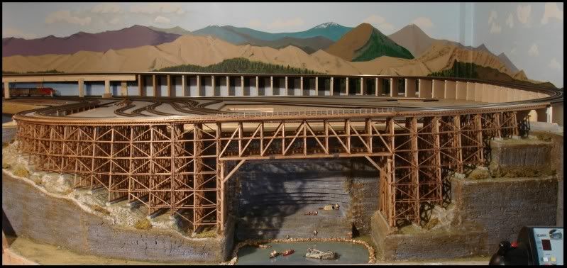
Ingeniero No1 posted:It has been a while since I updated, and that is because I have been busy building the trestle - remember? I named it the Judy Jane Trestle since my wife has really been helping me all along both finishing the basement, and now the layout.
More pictures here here: Judy Jane Trestle
Alex
Alex
When I click on Judy Jane Trestle it takes me to OGR's homepage. Is it supposed to do that? I would think that a hyperlink would take you directly to something. Help me figure this out please.
Mike
Mike,
I need to look into this. I am not on my own computer now, but will be in a couple of days, and will let you know.
Alex
Ingeniero No1 posted:Mike,
I need to look into this. I am not on my own computer now, but will be in a couple of days, and will let you know.
Alex
Don't mean to butt in Alex., but that post appears to be from 2011 and I think you might have been trying to take us back to earlier photos of your progress on the trestle here. The link probably worked back then, but references might have changed somewhere along the way.
Thank You DoubleDaz,
Is there an archives where his photos might be so I could look at them?
Mike
mknight1957 posted:Thank You DoubleDaz,
Is there an archives where his photos might be so I could look at them?
Mike
Not that I know of. There is the Video Clips menu option, but AFAIK members have to specifically upload videos and photos there and not many do. I tried using the Advanced Search option to find Photos posted by Alex, but didn't get any results.
Very Impressive and the treads are great
JerryG posted:Alex,
Thanks for your kind attention. I decided you are right and ponied up the cash to trainshanty.com, who seemed to have the best price. I watched a video comparing the options, and this clearly made the most precise cuts. One question, have you ever had to replace the wire for your Woodlands unit?
Jerry
Hi Jerry,
Better late than never?
No, I have never had to replace the nichrome wire that the cutter uses to cut through the foam. I bought a spare, which has enough wire for three replacements, but have used it.
Alex
DoubleDAZ posted:mknight1957 posted:Thank You DoubleDaz,
Is there an archives where his photos might be so I could look at them?
Mike
Not that I know of. There is the Video Clips menu option, but AFAIK members have to specifically upload videos and photos there and not many do. I tried using the Advanced Search option to find Photos posted by Alex, but didn't get any results.
Dave, Mike -
I have tried three times, with searches and a lot of reading, to figure out to where that link should have taken us, but have not found anything. I suspect that that mysterious link was to additional construction pictures, of which I have a lot that were not in the magazine article and were never posted, and will assemble a new post with to include those.
Thx!
Alex
My photos were taken off by because I am in the process of maybe being published in another magazine. So they asked not to show any photos until after. Now hopefully I will get pubilshed soon if I do I will put the photos back on if I don't I will put the photos back on. My son and I are excited so we hope this doesn't take to long not bad for two novices.
Mike
Congratulations Mike on getting published! I'll look forward to seeing it on the other magazine!
Mark,
We are in the process but nothing is written stone yet. We hope to be published but just the thought of being published is pretty cool my 13yr old son is excited so we cross our fingers and we wait ��
Mike
Mike, Sorry I misread. I hope you do get published! Thank you
I've only seen one other layout this size. You've done a phenomenal job with this.
mopac01 posted:I've only seen one other layout this size. You've done a phenomenal job with this.
Thank You!
I have made a few improvements and I am working on a new video, but I am hesitant of posting anything until an already written article is published; hopefully soon. ![]()
Alex
I can't believe I have missed this thread over all these years you have been working on your layout. It's probably my age and I have been a little busy trying to copy great ideas from all the artists on the forum. In any event, wonderful work.
pennsynut posted:I can't believe I have missed this thread over all these years you have been working on your layout. It's probably my age and I have been a little busy trying to copy great ideas from all the artists on the forum. In any event, wonderful work.
The same thing happens to me. Every once in a while I find a new-to-me thread that is several pages long, about a great project or layout, which somehow I had missed. Glad you found it!
Alex
Alex, I am just getting started reading about your layout, and from page 1 through today, page 12, it’s an amazing Journey with a beautifully executed plan of action. I have not found the video’s yet but your attention to great construction and your track work is meticulous. I look forward to reading more about your layout. Thank you for posting your layout for our education as your ideas are novel. We learn from others in the hobby, Gunrunner John, who has a new layout in a progressive stage, and Mike G, with layout work in progress, Farmerjohn in Ken, and so many others, it’s simply fun to read all about there work. One thing for sure, your hanging Millhouse turntable is a super idea,....Wow. Keep posting, we’ll keep reading about your “Hidden Pass Junction RR”, model railroad. Happy Railroading
LEAPINLARRY
if you like the pics
you should see it in person
it’s awesome and that doesn’t even begin to begin to begin to describe it
a true work of a craftsman
1Drummer, all I need is an invitation and I would love to see this layout. I looked up Alex’s profile but did not see the state he’s living in. It would be a great trip for our group here in Tennessee/Kentucky/Indiana.....Thank You....
LEAPINLARRY
I first saw this Railroad a few years back-Alex had an open house after a train show in St Charles MO..
Have you looked at his YouTube videos?
Alex lives in Wright City, MO. We have had the pleasure see this wonderful layout several times. They are GREAT guests and you will love the layout and talking with this couple.
Hello one and all!
I haven't posted in a while, but not due to lack of interest - just other 'distractions'.
Anyone in this forum is more than welcome to visit and take a peek at the layout; just drop me an email or message. We live about a mile and a half south of I-70 exit 200; about 50 miles west of downtown St Louis.
Thx!
Alex
PS. You can access my YouTube videos at my channel: 03patines (that is zero-three). Note that some of the train videos are from my first layout; I started work on my present layout, the Hidden Pass Junction RR in Feb 2011. Started running a few months later, and by summer 2012 all the track and most of the wiring were done and operational. I have added a couple of spurs since then, and lots of buildings and scenery in the last three years. As of the end of 2018, I was close to 27,000 feet of wire for the track power and control, lighting, accessories, and switch-track operation and detectors.
Really nice job Alex. I've been here before because i remember that cool bridge & the hatches. I'm planning on going back and reading thru all the posts from beginning to present. Lots of great ideas and info here. I understand how much time is involved in taking on a project like yours. I'm all excited to get ours started when these travel restrictions are lifted. I live in Steubenville OH. The layout is at my son's house near Atlanta, so my update posts will be months apart. Hoping in June to finish the wall wiring and plugs, get the drop ceiling and lighting done, and lay the vinyl floor. Then late summer install drywall and build the two false walls. That should get us ready to begin table construction at Christmas (I hope). BTW, My nephew lives near Scott AFB. If i ever get a chance to get down to see him, i'd love to see your layout in person. Thanks for sharing the posts and pics of your layout. I'll be back with questions.

Access to this requires an OGR Forum Supporting Membership