Please read and review the topic "K-Line Heavyweight LED Striplighting Conversion - General" before proceeding.
Conversion of the K-Line heavyweight observation car's interior to LED strip lighting is straightforward and no different than other cars. However, the observation car also has rear platform drumhead and marker lights, all grain-of-wheat bulbs. For reasons discussed below, converting these lamps to LEDs presents some significant complications. However, the incandescent bulbs can be retained if an independent power supply is provided for them.
The following picture shows the front end of the car, with constant-current LED strip regulator in place. The red and black wires on the opposite side of the carbody ceiling are a track power feed for the tail end lighting, as discussed below.

The marker light fixtures have red lenses fore and aft, along with a yellow lens to the side. A white light source is necessary inside them. Unfortunately, most dome-shaped LEDs do not achieve a minimum dispersion angle of 180°, which is necessary for balanced and efficient illumination of all fixture faces. Keeping the grain-of-wheat bulbs in place avoids that problem.
The rear platform illuminated drumhead is basically a plastic box that appears to be glued in place. To use LED illumination, the box would need to be removed and opened. This is much trouble for minimal benefit, so like the markers, keeping the existing incandescent bulb makes sense.
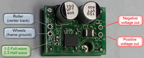
The rear marker and drumhead bulbs are all wired in parallel. Circuitry of the K-Line Streamlighting circuit board (two diodes in series in each AC direction) sets the voltage at 1.3 to 1.5 V (depending on diode forward voltage drop). With the LED lighting strip powered at a nominal 12V, the incompatibility of the strip's constant-current regulator with these bulbs is obvious. Moreover, the bulbs draw approximately 100 mA, outside the design range of Rod Stewart's regulator. The solution to this issue is to install an independent power supply for the tail end lighting.
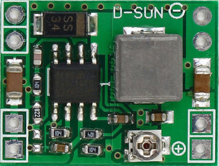
Gunrunner John identified a compact, low-current DC>DC buck converter/regulator board that can be had for under $2 each, in packages of 5 (from the US mega-warehouse site). This device can be set for an output voltage down to somewhat below one volt. With 12V input and the tail-end incandescent bulbs loading it, the current drawn is around 25 mA, still high for use with the LED strip constant-current regulator. At higher input voltage, the current draw will be lower.
Some experimentation confirmed that it was not possible to compatibly power this DC>DC converter from the LED strip regulator. Fortunately, I had recently removed the incandescent lighting boards from some Golden Gate Depot heavyweight coaches and not disposed of them. The rectifier/filter section of that board could be used to interface track AC power to the DC>DC converter board. The GGD board was cut off just past its filter capacitor PCB holes. The 6V linear voltage regulator was removed, as it was not needed, and the capacitor folded over to occupy the space formerly devoted to the regulator. The DC>DC converter input was fed from two of the three the PCB holes formerly occupied by the regulator. The AC input pads of the board were fed from the track power feed to the LED strip regulator, at the front of the car. The next picture shows the rectifier/filter board and DC>DC converter/regulator, glued to the ceiling at the rear of the car. Had I been willing to lay out a PCB for the rectifier and have it made, considerably less space would have been needed. But it really doesn't matter, as there's plenty of open space in the car.

Note that the marker light wires are held in place by tape, rather than hot glue. Since they're incandescent, replacement may well be needed at some future date - and extracting the glue would not be enjoyable!
The DC>DC converter/regulator output was adjusted to 1.4V. This is well below the maximum voltage of the grain-of-wheat bulbs, but seems to set the marker and drumhead illumination levels realistically - and essentially matches the original K-Line voltage. All three bulbs were wired in parallel.
Setting the LED intensity is a bit different than for the other cars. Here, the track current is that of the LED strip plus that of the tail end lighting. So the regulator board pot should be set to about 12-15 mA higher, or approximately 50 mA AC current draw from the track.
Here's a picture of the completed car, on the rails: