
Hello,

This is my first post on the forum, but I have gotten a lot of advice already from reading it.  I have been in the hobby most of my life and have done several layouts over the years, but have never had a space for a permanent layout.  Now I am working on creating a long term, permanent layout in my basement.  In the past, I have always gone the traditional route with lionel tubular track and conventional control.  With this layout I want to use gargraves track, ross switches and DCS control.  I have designed a layout using RR track software and have included it here.  The black track is the bottom level.  The blue track is the upper level and the red track is a grade going from the bottom to the upper level.  According to the software, the grade is 3.4%.  I have designed the lower level with minimum 072 curves so I can run anything there in the future.  The upper level and the grade I went smaller (063, 054, 042) due to space.  I would love any suggestions, advice or critique.  Since I am going to be new to using gargraves, ross, dcs, etc, please let me know if what I have designed won't work in reality.  Thanks in advance!

Layout Design

Attachments

Images (1)
  • Layout Design
Last edited by Michael Cimba 040217
Original Post

Replies sorted oldest to newest

I like the connection between the upper and lower levels, that looks like an interchange between two railroads.

I use gargraves track and ross switches, and it looks like the plan itself will work for running trains. If you plan on modeling other than the CNW, your trains on the outer loop will be running counterclockwise,  so that spur on the left isn't going to be easy to access, plus it faces against your yard. You may want to run it off the middle of the curve, oriented north south rather than east west, and put the switch at the other end so deliveries by local freights can be picked up by your yard engine and shoved back to the yard.

As for the upper level, it looks like you have an operating loading dock of some sort. In the real world, this would be on a spur, not alongside the main like a passenger staion. You could put it along the spur to the left.

Your backshop looks good, but one of your yard tracks comes right off the main, and puts the main through the curve of a switch. Experience has made my shy away from this, as some engines that can handle a normal curve will still derail going through the switch curve at speed.

All in all, though, I like the two levels, and it makes me think of a class 1 on the lower and a short line on the upper, with an interchange.

Last edited by Trainman2

I like it overall- 3-4 trains on the mains and switching. Looks like a good variety to keep interest.

I would shift the top set of crossovers to the right and extend the yard lead by moving that switch to the left. This will give you more room to work the yard without fouling the main line.
The short spur on the left could be put on the other end of the curve so you don't have to shove a car in (assuming CCW running). |
Shift the short spur on the right to come off track one in the yard. You could curve the spur into the corner and build a coaling facility for steam engines.
Access to the middle? Are you adding pop-up doors or will you have access all around.
Don't know what your scenery plans are but on the upper level you could do a few industrial spurs inside the right reversing loop. The PRR and WM (two of my faves too!), ran a lot of freight and coal. One can never have enough switching IMHO.

I don't run DCS but go get Barry's book on DCS and read it before you start.

https://mthtrains.com/DCS_Companion

Keep us posted on the build.

Bob

Last edited by RSJB18

Thank you for the feedback!  I appreciate everybody's ideas and suggestions so far.  The expertise is invaluable.  I will reconfigure the design when I get a chance and post it again to make sure I'm understanding the suggestions correctly.  As far as access, the room is the size of the layout with an additional 3 to 4 feet of walkway on the left side.  The white space is also 2.5 feet of walkway on the top and bottom of the layout.  The right side is against a wall as well as the bottom right and top right sections.  I was planning on doing a backdrop around the sections that are against the wall.  I was going to do some openings in the middle for access.  A rough scenery plan was to have the bottom level somewhat industrial (especially around the yard/backshop area).  Maybe do a farm scene on the left side bottom level between the bottom level and the top level.  And then the top level was going to be a country town with a little industry and possibly a carnival.  The top level will essentially be on a mountain with tunnels running through it for the bottom level. 

What would be a good height for the top level?  The bottom level is at 33" from the floor.  I was thinking 7.5" for the top level which gave me a 3.4% grade going from bottom to top but that might not be enough height.

Barry's DCS book is on my list to get as well as the OGR DCS DVD.

Thanks,

Michael                

Michael- The yard and spurs on the upper level look good.

I agree with NECRAILS, access to get at that double cross-over is a must.

I'm a tall guy so I prefer a higher layout. Raise it up to what feels comfortable to you. Remember lots of bending over while building. Access underneath for wiring is often overlooked too. It depends on your audience too, small kids would need step stools if you raise it.

For the height of the upper level, measure your tallest equipment including the track and adjust accordingly. I think 7.5" is a bit high but depends on what you run. If you can lower it then the grade will be easier for long trains to pull. Watch clearances on curves and check as you go.

Definitely a solid plan and a great start.

Bob

NECRAILS and RSJB18:  Thanks for the advice on the switch access.  I didn't think about that being a problem, but I can see why it would be.  I reconfigured the layout and moved all the switches on the upper level so they were more easily accessible. 

I did a layout a couple years ago that was higher, closer to 48" for the lower level.  I decided that was too high.  So, I decided to lower this one.  I do have small children and that was definitely a consideration.  Also, because the layout is so wide I wanted to have as much arm reach to the center from the sides that I could.  I definitely understand the issues of bending over and doing wiring underneath.  I will figure out what works best for my situation.

Thanks again for all the great advice!  Here is my reconfigured design.              

Attachments

Images (1)
  • Michael's Layout_REV C

Good comments from everyone - you will want the DZ-1000 switch machines with the Ross switches. 

One thing that will be new to your O building is using roadbed and having to ballast. Midwest cork.

It may be easier in some locations to put the switch motors opposite of where you have them because of roadbed fitment and allowance for ballast. It appears that you have the space to choose either side on almost all of them.

Would you care to share the file? I was trying to visualize any possible tunnel or elevated track issues. The 3D can still be helpful, even though it is not the easiest to work with. 

Have you run the train simulator to check the play value?

Last edited by Moonman

Hello MOONMAN:  I have attached the file.  I am currently using RR Track V4 that does not have the train simulator but I was thinking about upgrading to V5 so that I could run trains through the layout to check clearances etc.  I was curious about tunnel clearance since most of my portals will be on curves.  

Any thoughts on top mounted switch machines vs under the table either the DZ-1000 or Tortise for this layout?  Obviously the under the table looks more realistic but I have read it is a ton more work and difficult to setup.  I agree about switching the location of some switch motors.  I didn't realize how to do that in the software until just now.

Any thoughts on cork vs foam roadbed?  I have heard that the cork can dry out over time but I have never used either so I am open to both.

Thanks for the great comments. 

Michael  


Attachments

Good Evening,

I have been slightly tweaking the layout plan this week.  I added a passing track on the lower level left side with 2 spurs.  I thought these could be for grain cars as I will have some grain storage in that farm area.  I also started laying out some buildings to see generally how the structures and scenery might fit.  I have included the latest RR Track file for anyone interested in looking at it as well as the new layout plan and some 3D views. 

I upgraded my RR track software, so I now have simulation capability and I will be running trains through the layout this weekend to check everything operationally.  I also got Barry Broskowitz's DCS books so I will be reading them as well.

Still curious for opinions on Cork vs Foam roadbed and table top mount switch motors vs under table mount (either DZ 1000 or Tortise) for this layout.

Any additional advice is greatly appreciated.  Thanks for all your help so far!

Michael       

Attachments

Images (6)
  • Layout Plan_11-8-19
  • Layout View 1
  • Layout View 2
  • Layout View 3
  • Layout View 4
  • Layout View 5
Files (1)

GFTIV:  Thanks for the suggestion.  In addition to those two, I also have one other switch under the scenery on the lower level that connects the reversing loop back to the mainline.  Is it a bad idea to have any hidden/non accessible switches or do you think those (2) Y switches might be more problematic than a regular switch?  I'm assuming the issue is possible derailments that you can't get to to fix.  

I have been trying to change the (2) Y switches in the double reversing loop to a cross over track while still maintaining minimum 072 curves in reference to GFTIV's suggestion, but I haven't been able to get it to work successfully and line up.  Maybe this is where flex track comes in.  Here is a picture with the 2nd level hidden to see the spot I'm working on.  Any help would be appreciated.  Thank you!

Michael    

Attachments

Images (2)
  • Layout Plan_11-9-19_LEVEL 1
  • Layout Plan_11-9-19_LEVEL 1 with X

What are your thoughts on leaving the (2) Y switches in the layout under the 2nd level scenery but having access to them from under the table in the case of an issue or derailment.  I'm just trying to get this design nailed down so I can start moving forward.  But, never having done a layout this complicated, I appreciate everyone's input to hopefully avoid future problems.  The advice already has been tremendously helpful.  Thank you.  

Michael, 

I did a lot of research on this forum and sought the same feedback you are seeking now.  These were the things that were passed on to me...

Don't think now... Think 10-15 years from now when you are older and not as mobile.

Can you physically reach everything on your layout from a standing position?

Do you want to crawl on the floor under the layout to get to access hatches?

You have a 13x16 grid.  Is this the size of the room or just the size of the layout?  Can you walk around it?  If not, how to do plan to get from the open area on the bottom to the open area on the top?

Bob (RSJB18) above recommended you consider the height when working on top.  Also consider the height when working on the bottom.  I'm 6'4", so when I need to sit on the floor to work on any wiring for anything, the layout is tall enough so I don't have to crouch and I won't hit my head on anything.

I don't want to derail your plans "pun intended", but you may also want to consider an around the room layout with a lift bridge from wherever you enter the room.  That will put you in the middle and give you access to everything.  It will also make all of your building and scenery easy to install, clean and refresh.

My first layout was a large platform for the kids when they were tots.  When my son was 11 we tore down the platform and started building our around the room layout.  That was 6 years ago.  I'm 52 now and very happy that I do not have to worry about accessibility.  I'm sure I'll be even happier at 62.

Just some things to consider.

Have Fun!

Ron


Michael Cimba 040217 posted:

I have been trying to change the (2) Y switches in the double reversing loop to a cross over track while still maintaining minimum 072 curves in reference to GFTIV's suggestion, but I haven't been able to get it to work successfully and line up.  Maybe this is where flex track comes in.  Here is a picture with the 2nd level hidden to see the spot I'm working on.  Any help would be appreciated.  Thank you!

Michael    

Michael- I tried different configurations ( I use SCARM), with various crossovers but couldn't get everything aligned. Flex track may be your only option here with the 22 deg cross. I would try to eliminate the switches under the center at all costs. I could live with the one remaining switch on the lower right.

As you build the layout you will find things that don't fit as you thought they would. This is probably one that you have to build to figure out.

Bob

Last edited by RSJB18

Thank you everybody for the great input and feedback!  OMAN and RSJB18:, thank you for taking the time to configure the crossover.  I have gotten it to work in RR Track.  There is a slight misalignment with two tracks that I have shown in a close up view.  I don't know if this is an issue or if the Gargraves track has enough play in it to make this work.  If the stock curve won't work I think a piece of flex track should.      

RON045:  thanks for the great advice and encouragement.  I have included a more descriptive view of the layout in the room.  It seemed like this configuration was the best for the way my room is laid out, but I am trying to take all the advice into consideration.  I am definitely trying to think long term and not get half way into things and say "I wish I would have.....  That is where this forum has already been invaluable.

Thanks again!

Michael  

Attachments

Images (2)
  • Michael's Layout_11-10-19
  • Michael's Layout_11-10-19_Close Up

You may want to consider a longer lead track to the yard. If the lead is longer than the longest siding, you can work each of the yard tracks, (sort the leads to build a train), without fouling the main line.

You could have a longer lead track if the track to the yard started on the left side, next to (above) the switch that goes to the upper level. This will allow you to switch the yard and also run trains on the main line, without any interference. If you are running trains by yourself, this is a convenient feature.

the longer lead also lets you combine a few of the yard tracks into a train, ready to enter the main line. this will clear space in the yard for an incoming train that needs to be broken down.

Good luck with your layout.


I just finished updating the layout yet again.  I shrunk the width of the lower level to make the reversing track crossover fit better.  I added 2 #175 crossover switches instead of using 8 individual switches to go between track's 1 and 2 on the lower level.  I lengthened the yard lead even more per JOE K's suggestion and tweaked the yard a little bit.  

Attachments

Images (1)
  • Michael's Layout_11-11-19
Michael Cimba 040217 posted:

I just finished updating the layout yet again.  I shrunk the width of the lower level to make the reversing track crossover fit better.  I added 2 #175 crossover switches instead of using 8 individual switches to go between track's 1 and 2 on the lower level.  I lengthened the yard lead even more per JOE K's suggestion and tweaked the yard a little bit.  

I just don't understand how you will be able to reach the top right and lower right sections of your layout.  Even with access hatches.

Hello Everybody, 

I have been playing with the layout design some more this weekend and here is another iteration.  I re created the upper level and added an up grade and a down grade so that you can go up and down from level 1 to level 2 on two tracks vs previously having to reverse on the upper level and go back down the way you came up.  I also tried to show my rough ideas for access hatches to access the right side of the layout.  The black track is level 1, the blue track is level 2 and the red tracks are the grades from level 1 to level 2.  Please let me know your thoughts!

Michael    

Attachments

Images (1)
  • Michael's Layout_11-16-19

Good evening,

I have been working in the train room the past several months and I thought I would give a brief update of my progress so far.  The lower level of the benchwork is almost complete.  I still have to add a small extension on the right side.  The second level benchwork and the grades will be added later.  The entire layout has been traced on the benchwork so I know how everything should fit in real space.  The latest project is creating a framework on the back wall for the wrap around backdrop.  Next will be to mount 1/8" masonite to the frame and after that mount the backdrop.  After that is complete and the lower level benchwork is finished I will be ready to start laying track and roadbed on the lower level.  In conjunction with that I have to finish my electrical plan.  My goal is to hopefully have something at least running on the lower level by Christmas.  Hope you enjoy and hope you are all staying healthy and well!  God bless!

Attachments

Images (1)
  • Train Room

I thought I would clean this up a bit, lay the groundwork for the final layout design and show some of the earlier progress of the build.  Here is the final layout design that I settled on.  The track is all gargraves phantom and the switches are Ross custom with Midwest cork roadbed for the track and Ross bed for the switches.  There are 3 individual loops connected plus the yard.  The blue track is a second level and the red tracks are grades going from level 1 to level 2.  I am powering this with (2) Z4000's.  Each loop will get one side of the transformers and the yard will have one side.  I am going to be running the full DCS wifi system.  This will allow me to run both my MTH proto 2 & 3 engines in command mode as well as my postwar Lionel's conventionally.  I am going to use Z1000's for switch and accessory power. 

Michael's Layout_11-19-19_ALL LEVELS

After years of setting up and taking down Christmas layouts I am now blessed to have a dedicated train room in the basement for this permanent layout. 20190925_08191520190925_081937

Once I had the room ready, I was ready to start building.  I had some leftover bench work from a previous layout that I was able to reuse.  I modified some of the framing members to accommodate my new layout and I added additional benchwork.  Benchwork consists of 2x4 construction with a 3/4" MDF plywood top.20191019_13255320191019_21442720191019_214420

After the lower level benchwork was mostly built I laid the lower level track out to see what it looked like in real space and I traced the layout onto the table top.  I also drew the framing members on the table top so I could see where to screw into as well as knowing where the track would lay relative to the benchwork.20200222_19254920200328_19394920200329_215701Additional benchwork modifications were made20200328_150714After everything was traced I removed all of the track.  I screwed the table top down.  I then cut access holes in the back two corners of the layout.20200525_17033120200531_165037I have some good helpers!  Hopefully I can pass my love of this hobby onto the next generation!

I also cut access holes to access the underside of the second level once it is added later.20200701_230707

I still have a little addition to the benchwork on the right side but it is almost finished.  Next I started adding furring strips to the back and side walls to create the frame for the backdrop.20200711_134941In the upcoming weeks we will be adding 1/8" mdf to the back and side walls which will be the base for the backdrop.  After that is mounted we will be ready to mount the backdrop.  

I will try to keep this updated with the progress.  Thank you for all of your assistance!  Hope you enjoy!  

Attachments

Images (16)
  • 20191019_132553
  • 20191019_214427
  • 20190925_081915
  • Final Layout
  • 20190925_081937
  • 20191019_214420
  • 20200222_192549
  • 20200328_150714
  • 20200328_193949
  • 20200329_215701
  • 20200525_170331
  • 20200531_165037
  • 20200701_230707
  • 20200711_134941
  • Michael's Layout_11-19-19_ALL LEVELS
  • 20190925_081915
Last edited by Michael Cimba 040217

Michael, I just found your topic, and I must say you are going in a great direction with this layout.  Congratulations on having the space to build it.  I went through a long period without layout space while our daughters were growing up, and now that the last one is married, I have gained a room for my layout build.

One thing, I can not see the first two images, which I think are your current track plan from your reference.  The photographs of your step by step construction look great.  I used GarGraves Phantom Line track, Ross switches, Midwest cork also.  I wish now I had used the Ross bed for under the switches since cutting cork to fit properly is a challenge for me.

I was wondering how you were going to access, but then I read on and saw the many access holes to the upper levels.  Bravo!  You look young enough to crawl under and pop up for years to come.  I approaching 64, on the other hand had to build an around the room layout with a lift up access bridge to the center operating area.  My plan in SCARM called for similar grade and a 6" level separation.  In practice, mine ended up at about 4% and 7 1/4" level separation.  Testing has shown that that grade works fine for the short trains I will run on the layout.  

I like the furring strips for the backdrop.  My layout room has one brick wall that I didn't want to put holes in, so I have mounted the backdrop on braces attached to the layout and notches cut in the hardboard that slip over the joists.  I didn't get it in from the beginning, so some places were a bit of a challenge.  I advise getting the backdrop up soon.  You may be able to crawl on the layout, the framing looks quite strong enough.  I am not able to crawl up on mine, though it would easily hold my 170 pounds.

I am really looking forward to seeing your progress!!  It looks like it will be a wonderful layout to build and operate!!  Congratulations!!!

Last edited by Mark Boyce

My dad and I have been working for the last two months on getting the backdrop up and it is finally finished.  This had to be completed before I could move forward with any other part of the layout.  Here is the step by step of what we did. 

First we cut, glued and screwed firing strips to the wall.  20200711_112939

20200711_125830

After the firing strips were mounted we added rounded corner supports.  

20200711_134941

Next we glued and nailed 3/16" masonite panels to the firing strips which would create the wall to mount the backdrop.

20200725_143600

20200725_151003

For the corners I chose to use an 8" radius due to space limitations of my layout design.  This is a tighter radius than most people use.  In order to bend the masonite panels we cut them into smaller strips and precut kerrfs on the back side of the entire radius. 

20200725_151514

20200725_171513

20200801_220638

After all the panels were up I then mudded the joints and nail holes to create a smooth surface.

20200805_213355

After 3 coats of mud with sanding in between we were then ready to hang the backdrop.  The backdrop was purchased from backdrop warehouse and came in 4 sections (lower scene A and B) and reverse gradient sky extensions A and B).  We used rubber cement to glue the backdrop to the backing.  It was a bit of a tedious process to get each section lined up and glued on properly.  It didn't turn out 100% perfect ( there are a few wrinkles and bubles, mostly in the corners) but all in all I am very pleased with the result!  If I ever have to do another one, I'll know what not to do :0).

20200829_153513

20200829_154315

My layout is going to loosley model the feel of the Pennsylvania and Western Maryland railroads in the 1940's to 50's so this scene will nicely set the stage for that.

20200905_231607

20200905_231622

20200905_231806

The next project will be to start laying some track for the lower level and start testing some trains for operations and clearances etc.  Until next time, thanks for reading.  Hope you enjoy!

Attachments

Images (14)
  • 20200711_112939
  • 20200711_125830
  • 20200711_134941
  • 20200725_143600
  • 20200725_151003
  • 20200725_151514
  • 20200725_171513
  • 20200801_220638
  • 20200805_213355
  • 20200829_153513
  • 20200829_154315
  • 20200905_231607
  • 20200905_231622
  • 20200905_231806

Ron045 thanks for the reply!  When I was working on the room before I built the benchwork I did contemplate the ceiling.  I finally decided that I was going to leave the ceiling open and never put anything else up there.  I wanted access to the pipes and HVAC and due to the height of the joists and the way the utilities are mounted any kind of ceiling would be a challenge.  So I opted for the industrial look. Thanks again for the suggestions and feedback, all very helpful!

Michael

Looks Great, nice job.  I like the backdrops, they add a lot to the layout.  I might suggest you think about painting the entire ceiling over the layout flat black, it will really disappear, and all the focus will be on the layout, especial with your outstanding backdrop.

Here is an early Photo of Bob Bartizeks Layout, you can see how the ceiling disappears and the focus on the layout.


Last edited by Rich883

Thanks for all the great input, Tom Tee, Mark and Rich883.  I wasn't going to paint the ceiling but now I can see that I might regret that decision down the road.  The flat black definately finishes it off and makes the layout stand out.  I will contemplate that decision before moving forward with anything else.

 I will re look at my grades and make sure I am happy with them and that's good advice about the pop up holes.  I don't want any skin rashes!

Michael,

First, congratulations on such a fine start to your layout! Well done! I like the thought that went into the track planning. I also love your choice of backdrop. Pennsylvania it is. 

Let me second Tom Tee's thoughts and suggestions. Before you go any further, please take care of the ceiling! Flat black paint works wonders at hiding distractions. It also has the added side benefit of sealing the wood above the layout. This can dramatically lower the dust accumulation down the road. It also has the added effect of maintaining accessibility while hiding everything in plain sight, including that ugly aluminum covered insulated duct work. If you go this route, be certain to adequately protect your backdrop. Black paint will really spoil it...

Here is a shot of my train room. I am VERY happy with the black ceiling and track lights. The fluorescent lights you see in the picture have since been disabled. The room is lit by only the track lighting. This does an excellent job of drawing attention to the layout, and nowhere else.

Chris

LVHR

A0050324

Attachments

Images (1)
  • A0050324

Good evening everyone,

It is finally time for an update after some of the progress of the past couple months.  Progress has been slow due to an ongoing family health problem, but I wanted to share what we have done up to this point.

First off I have decided upon a name for my railroad.  It will be called the "Allegheny Crossing".  I will be updating the title of this thread with that name.  The meaning of this name represents a couple things for me.  First Allegheny describes the general type of area I am modeling after the (Pennsylvania/Western Maryland).  Crossing represents the connection of these areas together but it also represents the bridge that was made when Jesus died on the cross for my sins so that I could be forgiven and spend eternity with Him.  The Lord has given me the ability to create this model railroad and everything that happens with it is dedicated to Him for His glory.

The last time I posted I received a lot of suggestions to paint my ceiling flat black before proceeding.  After thinking about it, I decided to get a painter to come in and do that.  I want to thank everyone for that advice and I am so happy I did that.  It makes all the difference in the world!

After the ceiling was painted we mounted a window air conditioning unit in the room to help keep it cool during the summer.  We also trimmed out the sides of the backdrop with white trim to finish it off.

After that, I re hung all my pictures, posters and signs on the walls to finish out the room decor. 

In addition to that, I built a control table for the transformers and control system components and laid them out on the table.

Next up I will be mounting a board under the table which will house my TIU, AIU's and terminal blocks.  After that it will be on to the first track work/testing trains FINALLY!

Here are a few pictures of the completed room and progress so far.

20201031_211407

20201031_211601

20201031_211448

20201031_211532

20201031_211754

20201031_211638

Attachments

Images (8)
  • 20201031_211407
  • 20201031_211407
  • 20201031_211601
  • 20201031_211448
  • 20201031_211532
  • 20201031_211754
  • 20201031_211754
  • 20201031_211638

With trackwork being the next major project on the layout I wanted to gather some advice on order of operations and best practices/tips/tricks.

As stated before I am using gargraves track, Ross switches, Midwest cork for roadbed under the track and Ross bed for under the switches. 

I know it is important to take my time and layout a section and test it for operation before proceeding.  Having said that, this is my first time using all these products so here are a few questions I have.

1.  Do you layout track and roadbed at the same time?

2.  Do you secure each section of track to the table as you go along or wait till an entire loop or operational section is completed and tested before securing it to the table?

3.  Do you paint the roadbed a color similar to the ballast you are going to use so it blends in better or is that overkill since the ballast will cover it?

4.  Do you test sections of track with alligator clips on the wire before permanently soldering the wire to the track?

5.  What are best practices to cut and bend gargraves flex track?

Any advice on any of these topics is greatly appreciated!  Thanks.

Michael

Michael, What you have proposed is very similar to what I have done.  The only difference is I should have bought the already formed Ross bed for switches.  I did know they made it, but forgot until I was well under way.  I found I have a harder time cutting cork the way I want now than I did years ago in HO.  Actually in the end, it won't matter because I plan to cover the cork with ballast someday, but that will be a future project.

1. I lay out the track on the tabletop the way I want it and mark the table with a Sharpie marker.  Then I take the track back up and lightly glue the cork down, weighting it or tacking it with tacks I can remove when dry.  I then sand the cork smooth to get rid of imperfections and the rough edge where you peal the two halves apart.

2.  I secure the track as I go along, doing sections at the most 6 feet long at a time.

3.  I tried the Rustoleum gray rock spray paint on the cork before laying track, but the tiny particles of white and black go everywhere.  Several Forum members suggested I go along with a sweeper (vacuum) hose to pick them up, but I am not too coordinated.  Instead, I paint the cork gray with a brush.  With just one coat, it soaks into the cork a bit, and leaves a mottled look which isn't half bad.

4.  I check out everything with alligator clips before making any permanent connections.  This go round, I tried the GarGraves rail pins with jumpers already soldered on, since I find soldering to rail more awkward and frustrating as I get older.  They give good conductivity, but I learned to feed them through a little larger hole than their diameter because the solder joint can break if you put too much stress on them when fitting them.

5. I have trouble bending GarGraves flex because it is so stiff.  Some modelers have suggested gripping it with two hands and bending it around your body.  I have used flex only for slight bends making connections where two pieces of straight or curved track don't fit smoothly.  It's a little more expensive, but does a better job for me and is much less aggravating.  Make sure you wear gloves bending flex.  If you don't get cut, you will at least have sore hands without gloves.

My way certainly isn't the only way, but it has worked well for me.  I look forward to seeing Allegheny Crossing come to life.

Number 5.  Cut and bend gargraves track. Any curve, less than O72, 72" diameter, best to use pre-formed curved sections. Larger curves, a template, to establish a uniform curve.    I used a large compass.   Atlas track screws were used.

Installing track screws every three to four inches.  Ball point is kept on the center rail as track screws are applied.  The curves are developed, in place, each track end has to be cut with a dremel.  Inside rail(s) will be longer on the curves.

Last edited by Mike CT

Mike, That is a great point that you recommend preformed track for any curves less than 072.  My curves are 054, so that helps explain the trouble I had with my early on experiment.  Good comment on the spacing of track screws.  The flex that I did use as mentioned above required closer spacing of screws than preformed track.  One side wants to raise up if there aren't enough screws.  It stands to reason once I observed it.

Mark and Mike,

Thanks for all the good advice.  That's generally what I was thinking, just wanted to make sure I was in the ballpark.  Most of the places where I am using flex track on my layout are to connect small sections between pre-formed curves, switches or straights.  A few places I am using larger pieces of flex track for custom radius curves but I believe they are all 072 or greater.

Do you have a preference on adhesive to glue the cork/foam roadbed to the plywood?  I'm thinking either wood glue or caulk.

Is there a disadvantage to using a brad nailer/pinner to hold the cork in place while the glue is drying?

Thanks!

Michael

Michael, Personally, I just put down a thin bead of carpenters glue under each strip of cork.  It is easy to get a scraper underneath and lift it off for reuse if I goof or change my mind.  I only use caulk on wood connections, and they can be a bear to pull apart if I realize I made a mistake.  You get the idea I make a lot of mistakes.  Mostly because I hadn't thought through some aspect of construction I haven't done before.

I do put in tacks to hold the cork in place, but leave the heads just off the top of the cork, so I can pull them out with a stiff pair of needlenose pliers when dry.  You really need them to keep it in position on curves.  I am thinking a brad nailer may press them down too far and dimple the cork, but I could be wrong on that since I haven't used one.

Mark, that makes sense, thanks!  I'm sure I will make plenty of mistakes as I go along.  My problem sometimes tends to be I over think things before I dive in (especially if I haven't done it before) and it takes a lot longer to make progress.  There is a balance between both extremes.  As they say, failure is the mother of success.

For cutting Gargraves track, use a Dremel tool with a 3" fiber impregnated cutoff disk. Do NOT,NOT, NOT use the little 1" ones that come in some Dremel kits! They are thin and shatter exceptionally easily. Nasty pieces fly exactly where you don't want the to go when that happens! Don't ask me how I know this! BTW, the next 3" disk I shatter will be the first one.

Regarding trackwork: After you bend it, solder your leads to it. I use my 3" disk to carefully rough the side of the rail, underneath the railhead. For the center rail, remove the black. Easy does it, you are literally scratching the surface. Decide if you are color coding your wire. If you do, stick with it! When you solder, use flux! It truly makes the job easy.

Also, I forget if you said whether or not you are planning to use DCS. If you are, please get a copy of Barry's book, The DCS O Gauge Companion. I think he was up to the 3rd edition before he passed away. Read it before you start wiring or laying track! He has a wealth of information packed into the book that will go a long way towards making your layout a delight to operate. Feel free to post your questions here. There are many people willing to help you.

Chris

LVHR

Chris:

Thank you for all the great advice!  I did get 2 of the cutoff wheels that Gargraves sells.  So I will be using those with the dremel to cut the track.

I am running DCS as well as Legacy/TMCC.  I have both of Barry's latest books for DCS and Wi-Fi DCS.  I have read through sections of them a while ago but it will be good to reread and refresh my memory now that I'm ready to actually start building.

I also have all the Black Diamond railroad dvd's which touch on a lot of the construction techniques mentioned above.  It is time to rewatch those as well.

Everyone here has already been an invaluable resource of information for my layout of which I am extremely grateful.  I am sure I will be asking many more questions over the course of construction.  Thanks!

Michael

Last edited by Michael Cimba 040217

Good evening,

Juat wanted to give a quick update.  I have spent the last month or so testing transformers, control system components and engines and getting familiar with using the dcs wifi app and the legacy cab 2 to control everything.  I setup a small test track to test my equipment.  It is definately a leap in technology from my days of running only post war lionel's conventionally, but WOW, all I can say is, it is a very gratifying experience and I can't wait to run the entire railroad. Now that winter is upon us and the yard work has come to an end I'm hoping to have more time to work in the train room.

This weekend's project was to work on the under layout control board that houses the tiu, aiu's, terminal blocks and wiring etc.  I got the board and some components mounted.  I have included a picture of the progress.

20201206_221347

The next project will be to build a second shelf for the main control table that houses the transformers, legacy base and wiu.  Once I get all that stuff mounted, I will be able to lay track and wire up as I go along.

I also included a quick picture of the top of the layout with some track pieces in the general area they will go.

20201206_221528

That's all for now.

Michael

Attachments

Images (2)
  • 20201206_221347
  • 20201206_221528

Michael it really looks great but I would consider a lot more lighting as the layout progresses you start seeing a lot of shadows and dark spots just where you will want to be working and then you will be trying to figure out lighting. Control them from several different switches so when you are operating you can better control the lighting. My layout room has a white ceiling with almost 30 6 inch LED lights and I have shadows and dark areas.


68F66AA0-D5A8-4550-BF06-D282313A3EBADAE8AEE0-B1BB-4E12-8845-466FF49926F835D17F3F-1931-404C-9FFE-1A8793FF5C2C

Attachments

Images (3)
  • 68F66AA0-D5A8-4550-BF06-D282313A3EBA
  • DAE8AEE0-B1BB-4E12-8845-466FF49926F8
  • 35D17F3F-1931-404C-9FFE-1A8793FF5C2C


3.  Do you paint the roadbed a color similar to the ballast you are going to use so it blends in better or is that overkill since the ballast will cover it?


Hi Michael,

Doesn't look like anyone has addressed your #3 question yet (unless I missed it, my apologies if so).

If the ultimate goal is to do some actual scenery, I start out by painting my whole layout surface with a good, all-around dirt color, such as a light tannish-gray, or whatever color represents the locality you're trying to model.  Water-based latex or acrylic paints works just fine for this.  I paint the whole layout surface, including the roadbed.

Then I come back in and paint my roadbed flat black or a flat dark gray before ballasting.  I fully paint the roadbed itself, then I brush out an inch or two minimum on either side of the roadbed.  This is where I let the brush start running a little dry on paint.  By painting the roadbed a dark color, if the ballast gets a little thin in spots, it looks far more realistic than having some bare, unpainted cork show through.  At least in my opinion.

Here's a pic I have showing this exact method.  I still haven't done any track weathering or ballasting yet, but that might happen over the course of this winter.  Note: my roadbed here isn't cork, instead I cut my own from some 3/16" thick foam poster board.  It's probably not as good as cork, but it will suit my purposes just fine in this particular case.

003

Attachments

Images (1)
  • 003

Thank you eveybody for the encouragement and advice! 

RJT:  Thanks for the suggestion on the lighting.  I'm pretty happy with the amount of light in the room right now.  I do have a few shadowy spots, but I'm ok with them based on thr scenery I'm gonna put there.  The lights are on a dimmer so I can create night easily.  I will add some light under the table especially by the control panel so I can see everything under there when I'm working.  Thanks for sharing your layout, I love the room and the layout design!

Mixed Freight:  Thank you for all the advice on painting the layout base and roadbed.  That is all good stuff to consider.  I will be adding scenery and ballast down the road so those are all good things to think about.  Nice looking train by the way!

20201209_222137

In general I have an order of operations question/dilema.  As you can see from the picture above I have sectional track and switches laid out with gaps where cut sections of track need to go.  I would like to cut the sections of track and assemble them to the rest of the track/switches to check clearances/run trains and make sure the layout works operationally. 

Is it a mistake to do that and then disassemble the track, come back and paint, glue roadbed down and screw the track down permanently? 

I know most of you say to go a section at a time which I also agree with.  But my fear is if I go section by section and glue roadbed down and lay track that I might have alignment problems and then I am stuck because I can't adjust it.

Maybe I'm over thinking this.  I want all my track work to be neat and aligned well and I want to do things in the right order.  I'm probably a little timid because I have never cut Gargraves track before and have never used roadbed before.  I have the layout drawn in rr track software with the track cut lengths labeled.  I also have transfered the layout to the table fairly neatly and acurately.

I am hoping I can avoid/prevent some common mistakes.  Thanks in advance for any help.

Michael

Attachments

Images (1)
  • 20201209_222137

Michael,

I like your approach of cutting and testing first before gluing the road bed, especially with the  curved switches I see you have.  Determining a true minimum O-72 radius through the curved switch with flex track leading up to it is challenge, even when scribed on the bench work.

I ran into this issue with two different O-72/O96 curved switch locations on my layout, where I used track planning software to really maximize my space using minimum radius of O-72, but found issues later on with some of my equipment requiring O- 72 where others engines with the same requirement worked just fine.  I should have spent more time on testing these areas with my all of my larger O-72 equipment before the more permanent installation.  It was messy and a pain to correct later on.

Michael, I cut and fitted my track, marked the location, then lifted it up, and then laid the cork.  I then painted the cork gray instead of black thinking it would look better in the interim before ballasting.  I like to ballast after the scenery next to the track is in.  Personal preference.  Paul's black paint looks good and will be a good base showing depth and shadows if any spot is missing ballast.  I didn't use black because I didn't think of it. 

Thank you eveybody for the encouragement and advice!


20201209_222137

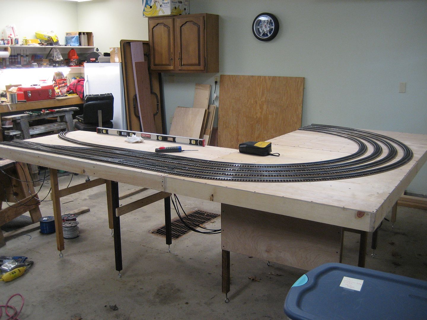
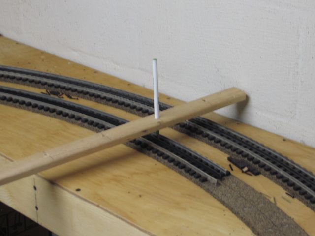
In general I have an order of operations question/dilemma.  As you can see from the picture above I have sectional track and switches laid out with gaps where cut sections of track need to go.  I would like to cut the sections of track and assemble them to the rest of the track/switches to check clearances/run trains and make sure the layout works operationally.

Is it a mistake to do that and then disassemble the track, come back and paint, glue roadbed down and screw the track down permanently?

Hey Michael,

No mistake at all, what you are planning on doing sounds perfectly fine to me.  I'd do it that way, too.

A few extra tips to consider that I can think of right off hand.........................

You might want to temporarily fasten all your switches and preformed track in the picture down to the layout surface, so they can't slide around while you're cutting the flex track to fit in between.  You might try using small nails, staples, or screws placed up against the sides of the rails and ties.  With screws, you could also employ steel or thin wood washers.  For nails or staples, don't hammer them all the way down, you will need to be able to pull them out later.  CAUTION: Be extra careful if hammering close to your rails, these hollow formed rail sections will dent very easily!  Denting the rail on an expensive switch will not make your day!

Start out by fitting and cutting your longest piece of flex track first.  That way, if you mess up, you can re-use this piece at another slightly shorter area and won't waste hardly any track in the process.  Besides, the more pieces you fit and cut, the better you will get at it (it won't take long ).

Having short pieces of fitter track makes good track alignment hard to do.  In some places you probably can't avoid it.  But for example, if you have a space requiring one full length of track and another only a few inches long, then consider cutting one piece of flex track in half and another piece slightly over a half in order to span the full gap.  This will make track alignment much easier in these areas.

If needing fitter pieces in curved areas, pre-bend the track to the proper radius before cutting the fitter piece.  The shorter the fitter piece, the harder it will be to bend it smoothly after it's been cut.

Once all your track cutting and fitting is done, you can hook up some power to it and run some trains over it to check out operation.  Or just roll some freight cars over the track and see how they behave.  Or you can simply eyeball it and make sure all the curves and straights flow smoothly together with no kinks anywhere.  Once satisfied, it's time to get ready for roadbed.  Mark the outline of all track pieces, then remove track in areas where you can start laying road bed.  Don't paint anything yet - you'll cover all your marked outlines!

That's it for now.  Once all your track outlines have been properly marked, laying roadbed is really quite easy.  You don't have to be near as precise as cutting and fitting track.

Hump Yard Mike, Mark and Mixed Freight:  Thank you so much!  That is exactly the "confidence" I needed.  I can really wrap my head around the way you described the process in detail.  All the suggestions, tips and tricks are very useful and practical and give me a good starting point.  All the wonderful folks on this forum make a daunting task seem do able for a newbie.  Thank you!

Michael

I want to wish everybody a healthy and blessed New Year!  Thank you for all the help and advice that has gotten the Allegheny Crossing off the ground.  I couldn't have started without all of you!

I haven't done much on the layout lately that I have to show for, but I have been doing some cleaning and organizing that has needed done.  I repurposed an old hospital medical cart that my grandfather had aquired somewhere into a toolbox/work area/wire cart. The tubes that hold the wire spools came from some old speaker stands I had lying around.  The other side of the cart has plastic bins that are perfect for housing oil, grease, glues, wire tires etc.  I put the cart in the train room during construction, so now I have most everything I need at my fingertips.

20201231_200812

20201231_200750

20201231_200802

I have also been doing some electrical planning.  Thanks to @Mark Boyce and the discussion on the Blackwater Canyon Line for great assistance in this area.  I have decided to use PSX-AC circuit breakers between the transformers and the TIU for extra protection.  I have also decided to put a TVS at every track feed.  I am going to use Wago Lever connectors for my wiring connections. 

Looking forward to hopefully making some noticable progress this year!

Michael

Attachments

Images (3)
  • 20201231_200812
  • 20201231_200750
  • 20201231_200802

Well it is finally time for an update.  I have been busy the past two months finishing construction on my control table, mounting all of the transformers and electronics and wiring up the control table to the control panel under the layout.  I will explain my setup and walk you through the progress.

First I built a control table.  I laid all of the electronics out on the table, marked and drilled mounting holes and wire holes.  I sanded the table, primed it white and then painted it black.  My son Benjamin helped me sand and vacuum.  He is a great helper and he loves trains!

20201213_171351

20201213_161439

20201213_161602

20210118_135520

20210118_135534

20210123_152630

My control table houses (2) Z4000 transformers for track power only.  I will have 4 loops/sections of my layout each run off of one transformer handle.  On top of the table is also the Lionel legacy base as well as the DCS WIU.  Underneath the table top mounted to the back of the control table are (4) PSX-AC circuit breakers (one for each transformer handle) with reset buttons mounted to the right of each circuit breaker.  The lower shelf of the control table houses  (4) Z1000 transformers.  These will be used for all accessory power.  (2) are setup to use the 14v output and (2) are setup to use the variable 18v output. The back of the control table has a surge protector that supplies all the power for the control table.

Once the table was built I first installed the PSX-AC circuit breakers.  I added LED indicator lights to show incoming power (green), outgoing power (yellow) and tripped (red).  I also added the sonalert speakers to each one for an audible alarm when the breakers are tripped.  I installed manual reset buttons for each breaker.  I tested each breaker prior to installation. Here is a video of the testing process and the breaker operation.

20210131_155259

20210131_155248

After the breakers were installed, I moved the control table into the train room and mounted the transformers, WIU and Legacy Base.  Then I was ready to start wiring.

20210131_162307

20210207_234355

20210207_234332

I phased all the transformers and found all to be in phase except for one of the Z1000's.  To correct this, I will flip the plug around on that transformer.  I tied the commons together on all of the transformers.  This proved to be a good use of the WAGO connectors.  They worked great.

20210207_234531

I wired each Z4000 handle output to the input of thr PSX-AC.  I then wired each output of the PSX-AC to the inputs of the TIU located under the layout.  I wired the outputs of the TIU to the appropriate terminal blocks and tied all the TIU output commons together as well as added the "one wire" from the Legacy Base.  The Legacy base is connected to the TIU through an LCS box so I will be able to run everything though the DCS app. 

20210207_234226

20210207_234203

20210207_234155

20210207_234145

20210207_234124

20210207_234133

20210207_234117

20210207_234057

Next up will be to start laying track.  Thanks for following!  God bless.

Michael

Attachments

Images (20)
  • 20201213_171351
  • 20201213_161439
  • 20201213_161602
  • 20210118_135520
  • 20210118_135534
  • 20210123_152630
  • 20210131_155259
  • 20210131_155248
  • 20210131_162307
  • 20210207_234355
  • 20210207_234332
  • 20210207_234531
  • 20210207_234226
  • 20210207_234203
  • 20210207_234145
  • 20210207_234155
  • 20210207_234124
  • 20210207_234133
  • 20210207_234117
  • 20210207_234057
Videos (1)
PSX-AC

Thank you Peter, John and Mark for the kind words! 

Mark, each PSX-AC has it's own speaker.  They are mounted directly to the board.  I'm not sure if you could wire them all to a single speaker.  I got them all from Tony's Train Exchange.  They might have an answer on that.  I wanted the speakers so I would know if there was a short even if I couldn't see the cause.  Since they are mounted under the table I wouldn't be able to see the lights easily either.

Michael

Tonight I mounted and wired the final terminal block for track power.  This one is going to power the yard, so I mounted it underneath the center of the yard instead of on the board next to the TIU, which is closer to the center of the other 3 loops.  That way I will have shorter wire runs from the terminal block to the yard tracks.  I also checked the voltage at each terminal block and they all checked out correctly.  Over the next couple days I will probably set up a test track and test each terminal block connected to that with an engine to ensure I'm getting good dcs and tmcc signal.

20210208_221545

Michael   

Attachments

Images (1)
  • 20210208_221545
@Mark Boyce posted:

Michael, I thought that would be the case.  I haven't jumpered for the manual reset or wired in the reset switches yet.  I got working on my liftup bridge, and once my mainline had two opening, I haven't bothered with more wiring.

Mark, I haven't had a chance to comment yet on your page, but I have been following your lift bridge project and it is impressive.  You're doing a great job!  I can't wait to see them when they are complete and operational!  I'm sure you want to get that completed so your mainline isn't fouled up and you can run trains again without them falling off the cliff 😁.

Michael, I can’t wait either.  Getting everything lined up right on the lift bridges is a little tricky for me!  Yes, I took a break from the bridges to fix a minor problem on my most expensive engine.  I did a test run very slowly, and went into Advanced on the DCS remote.  Then I tried to slow down without getting out of Advanced.  Of course nothing happened. 😱  As I moved over to break a fall, I fumbled to the right place and stopped the engine with 3 or 4 feet to spare.  😊  It was a wake up call to continue on the bridges exclusively until finished.  

Hello,

Just a quick update to show some of the progress I have made in the past couple months.  Progress has been slow because during the summer, much of my free time is dedicated to outdoor yard work and family.  Nevertheless I have been inching away at it when I have time.

I have rough laid the lower level double main line and reversing crossover.  All the track is screwed down so that I could get all the flex track pieces bent correctly.  This was a lesson for me in cutting and bending gargraves track.  I am pleased with the results.  All the curves flow together nicely and so far I have not wasted any flex track pieces 🙄.  The next step for this track is to put down the roadbed.  I know I am doing things backwards but I wanted to make sure my track layout was solid first.  I am going to attempt to slightly lift sections of track piece by piece enough to get the roadbed in place and glued down without having to remove the track completely.  After the roadbed is down I will probably wire this section up so I can actually run trains somewhere.  Then I will probably start figuring out my grades to the upper level and work on laying out the yard as well.

I will leave you with some pictures of the layout with a bunch of different train consists to give you a flavor of what I will be running on the layout.  Obviously I won't have all these trains running at the same time.  I setup the tunnel portals so you can see where the trains will traverse under the upper level once it is in place.

Happy 4th of July!!

Michael

20210701_22495520210701_22493420210701_22492120210701_22490020210701_22484420210701_22481820210701_22480320210701_22473320210701_22471020210701_22465920210701_224632

Attachments

Images (11)
  • 20210701_224955
  • 20210701_224934
  • 20210701_224921
  • 20210701_224900
  • 20210701_224844
  • 20210701_224818
  • 20210701_224803
  • 20210701_224733
  • 20210701_224710
  • 20210701_224659
  • 20210701_224632

Good Evening,

Today I completed the track work on my lower level double mainline, minus the ballasting which will happen at a later time.

20210906_212413I used a somewhat different method than most folks, but it seemed to work well for me.  I will detail the steps below.

Most people transfer the track plan to the table by marking out the center line of the track with marker.  They then use the centerline to lay out each half of the roadbed and finally they lay the track on top of the roadbed.

I started by roughing in my track plan on the table with pencil.  But because I had several custom bent curves, I wasn't sure exactly how it would lay out.  I wanted to make sure that all of my curve and turnout transitions flowed seamlessly into each other and that my track plan would fit properly on the table.  So I decided to lay the track out first, screwing down sections as I went and bending the curves so they would flow nicely.  Once I had all the curves bent and all the track layed out and roughly screwed down, I then marked both edges of the track ties with marker.  This was to make sure I knew where the bent curves should lay when I removed the screws. 

After the track was all layed out, I went back and started laying roadbed under the track.  I used a combination of foam Ross Bed under all the Ross switches and crossover and Midwest cork under the rest of the Gargraves track.  I started working section by section, removing the track screws, raising the track up enough to slide the roadbed underneath and then rescrewing.  I started with the Ross Bed for the switches.  This product comes as a tan, yellow or pink foam.  I decided to paint the Ross Bed before laying it down.  I used Krylon foam safe primer and 2 coats of Krylon speckled stone spray paint in the pebble color.  They ended up being a grayish brown.  After the Ross Bed was painted, I slid each piece of Ross Bed under the appropriate Ross switch and pressed the switch down into the Ross Bed.  It formed a very snug fit and I did not use any glue.  Once all the Ross Bed was in place, I used the same method for the Midwest Cork working my way around the Gargraves track.  I unscrewed a section of track.  Then I put dots of white elmers glue in between the track ties on either side of the center rail every 12-15 ties or so.  I slid the two halves of roadbed under the track (one piece on either side).  The glue helped to hold the roadbed in place.  I held the two halves of roadbed together with my one hand making sure they were aligned on the track while I screwed the track down.  I used thumb tacks to help hold the roadbed in place in areas where there wasn't a screw or at the end of a piece.  After a section of roadbed was complete, I ran a bead of white elmers glue along the edge of the roadbed and the table.  After the glue was dry I removed the thumb tacks.  This method seemed to work well for me especially after I got the hang of it.

I am pleased with the results so far.  I have taken a lot of time with the trackwork, but I want to have a very good foundation for everything else and not have issues later on.

Here are several pictures of the progress so far. Next I will be working on wiring all this track up permanently so I can have a fully functional double main line 😁!  I have waited a long time to see trains running around the entire loop.

20210906_21264620210906_21243920210906_21284620210906_21285920210906_21252720210906_21261720210906_21245020210906_21270220210906_212914

Enjoy!

Michael

Attachments

Images (10)
  • 20210906_212413
  • 20210906_212646
  • 20210906_212439
  • 20210906_212846
  • 20210906_212859
  • 20210906_212527
  • 20210906_212617
  • 20210906_212450
  • 20210906_212702
  • 20210906_212914

Looks really good!  I see no switch machines. Did you decide on under table mounts?

Thank you Dave, Mark and turkey hollow rr for the kind words!

I have not added any switch machines yet.  I have the DZ1000's for all my turnouts, but that is another project I will work on in conjunction with wiring up the track.  I still have not decided if I am going to mount them topside or under the table.  My original plan was to mount them under the table to look more realistic.  But, I also want solid operation.  I'm not sure if it is worth the hastle of trying to mount 30 switch machines under the table.  If there are any thoughts on one vs the other, I would love to hear!  Thanks.

Michael

Add Reply

Post
The Track Planning and Layout Design Forum is sponsored by

AN OGR FORUM CHARTER SPONSOR

OGR Publishing, Inc., 1310 Eastside Centre Ct, Suite 6, Mountain Home, AR 72653
800-980-OGRR (6477)
www.ogaugerr.com

×
×
×
×
Link copied to your clipboard.
×
×