Might Add a couple more Transformers.
Gee, I'm breaking my own word here, I wasn't going to comment again. 
What you fail to grasp is you can put a dozen transformers paralleled in that one location, but unless you change the wiring to the tracks, the voltage drops will still be there. If you have three hundred feet of track, my guess is you have some fairly long runs of wire to the track drops.
Let's use an example.
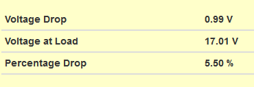
If you have 18 volts at the transformers, and 40 foot of #14 wire to the power drop at the track, and 10 amps of current in the circuit.

This line voltage drop will not vary no matter how many transformers you parallel. There is some additional voltage drop within the transformer with higher currents.
Change that 40 foot of wire to #10 wire and the picture changes, now the drop is only 40% of the previous value.
Note that change is JUST because of voltage drop in the wiring, this calculation has NOTHING to do with what's happening inside the transformer.