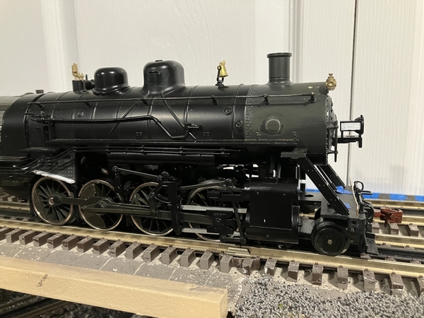
What a nice build, your 2-8-0 is so nice.
@86TA355SR posted:Which brand rivet decals are you using?
Thanks.
Archer. I also used ones from Micro Mark a few years ago, and only remember that I thought they were far harder to use than Archer's.
~Chris
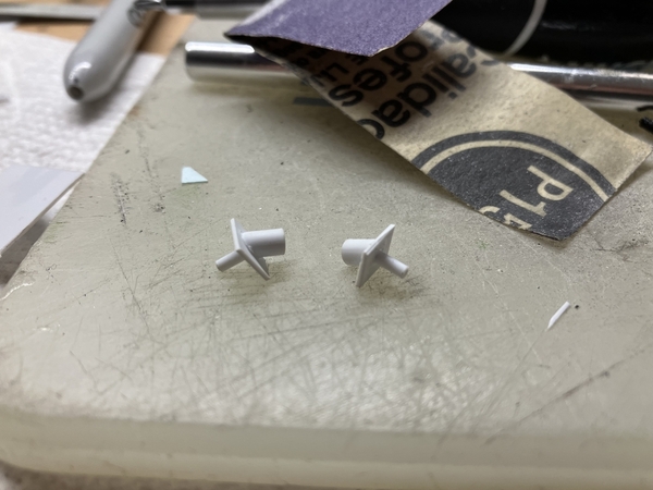
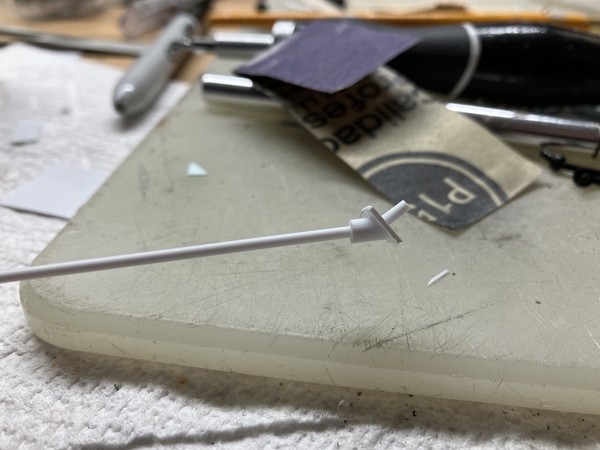
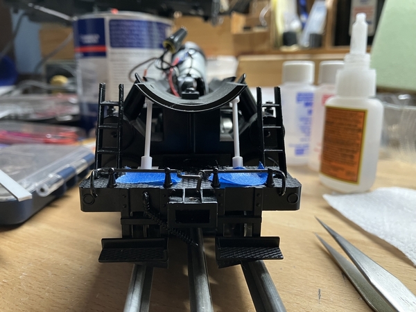
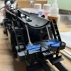
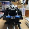
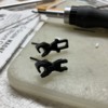
I made my own pilot support poles out of styrene and am now happy with them. Main bracket is made from sheet stock, a small tube, and a dowel. The pole itself is a dowel that fits snugly inside the tube.
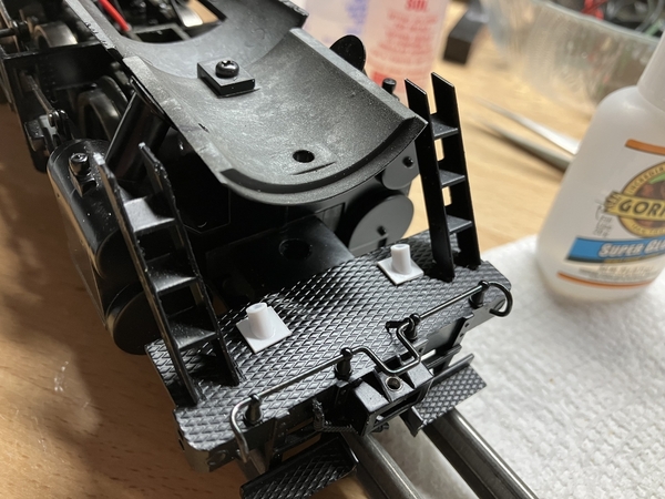
Using the same mounting holes I drilled for the original poles:
Fitting the pole:
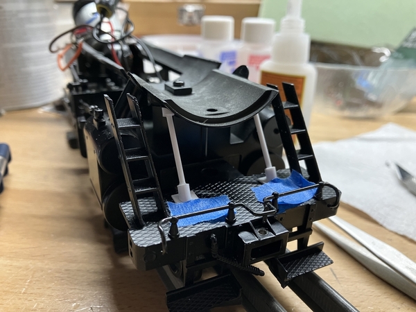
I used another piece of tube at the top of the pole to provide a visual transition onto the underside of the boiler. They are not attached to the boiler at all, but press up against the underside when the bracket is held flush to the top of the pilot (using blue painters' tape for the test fit). I'll paint these separately from the rest of the engine and add them after assembly to ensure they fit correctly.
~Chris
Attachments
A bit of progress over the last week:
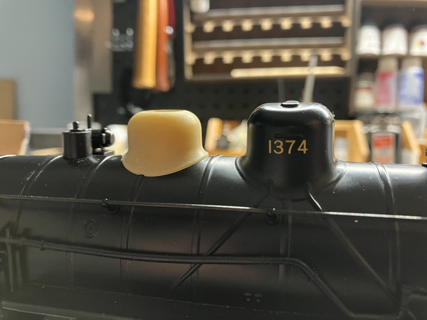
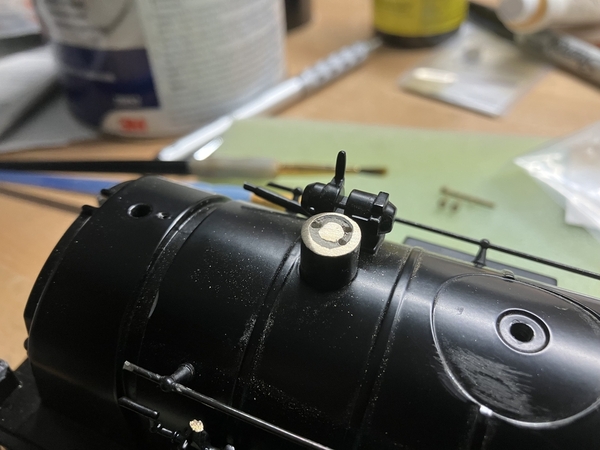
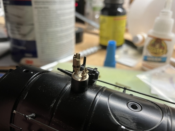
1. I received a new version of the steam dome, shorter and flatter up top. Looks much better to my eye.
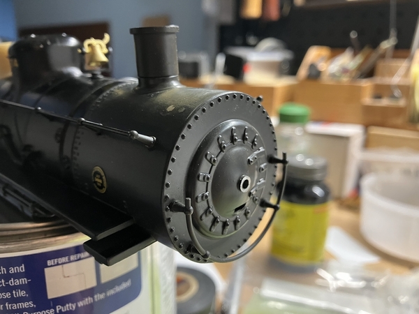
2. Front headlight bracket was removed, a piece of the boiler casting that extended into the headlight cut off, and the marker lights cut off and the holes filled.
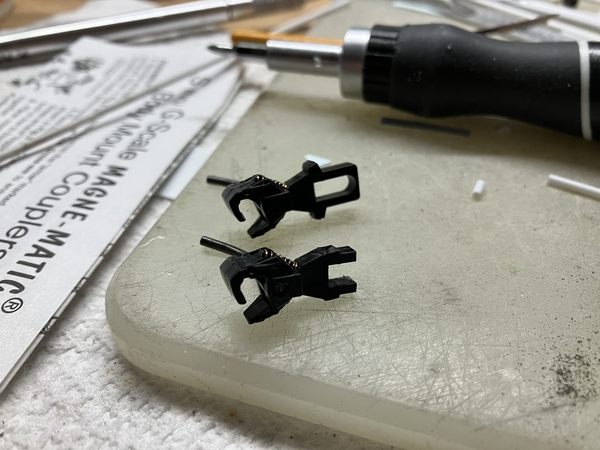
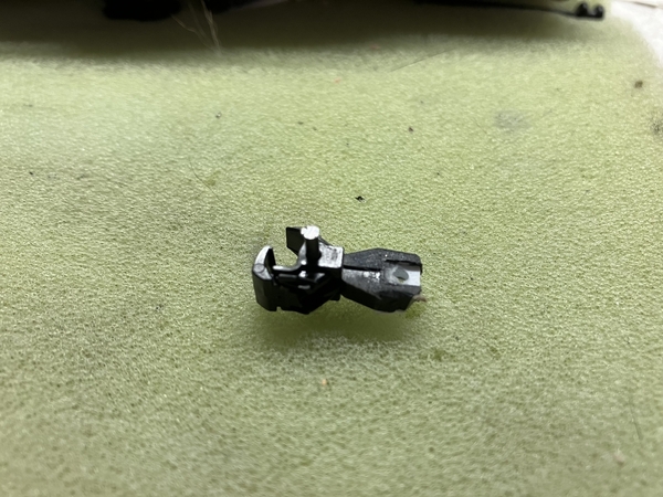
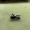
3. There was no room for a Kadee coupler box on the pilot, so I modified the coupler to mount to the existing cast-in box.
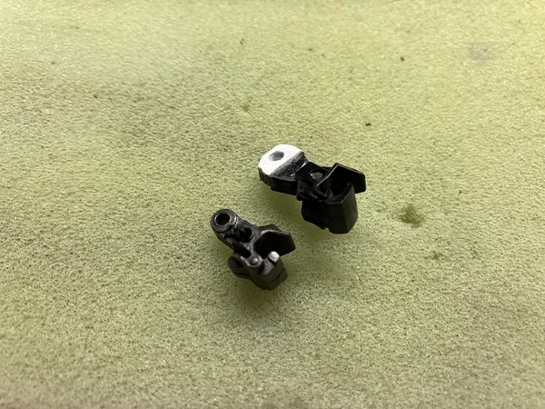
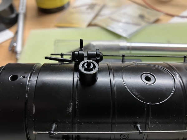
4. A new whistle and safety valves were mounted to this piece between the steam dome and cab.
~Chris
Attachments
Chris, nice solution to the front coupler by adding a piece to catch the screw where the spring would reside. The regular length Kadee’s don’t have a lot of meat on the shank after you drill the hole. I never thought of modifying the shorter version. I’ve gone to using the Atlas, Kadee lookalike. They are sold in a 4 pack without boxes. They offer a wider shank than the Kadee and a mold line that helps you find the center. You still need to file notches in them behind the coupler to get them to pivot properly in the cast pilot box if your doubleheading.
When you started this project. I went on the New Haven Google site to check out the photos. While not the particular engine your modeling. They were used in the Walpole, Norwood area of MA. . just a few miles from where I grew up. I’m guessing they served Bird & Son in East Walpole which had constant rail traffic.
The details your adding are making this on par with a full brass engine with road specific details. I’ve enjoyed following along.
Nice job on the Kadee.
Thank you Dave and Harley!
Dave - the idea of filling in the short Kadee came accidently. I purchased the short coupler to see if I could shoehorn in the shorter coupler box, and after I realized I couldn't I just made use of what I already had. Working well so far.
The regular assignments of the 15 F-5's in the 1940s were the local freights out of Waterbury and Boston, and that most likely included the Walpole local that served Bird & Son. There was a great article in the Shoreliner on this industry a few years ago, in Volume 35 Issue 3: "Bird Mills -- East Walpole on the Wrentham Branch". I'll dig out a copy when I have a chance and see if there is an F-5 in there.
~Chris
The headlight shape stands out when looking at the side profile of an engine, so that is an important detail for me. I had designed and 3D printed some proper Pyle National Golden-Glow headlights for my New Haven 0-8-0 project a few years ago and reused them here. Similar to the headlight on a New York Central Hudson, it narrows to a rectangular cross section behind the reflector. Reflector area is painted silver, number boards white, hand brushed on over the airbrushed black coat.
A handrail was also added to the pilot; from its size and location, I can only assume it was for use when a crew member was riding the footboard (only allowed when the footboard was at the "rear" of the locomotive, as dictated by the direction of travel, according to New Haven rule S.92).
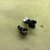
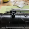
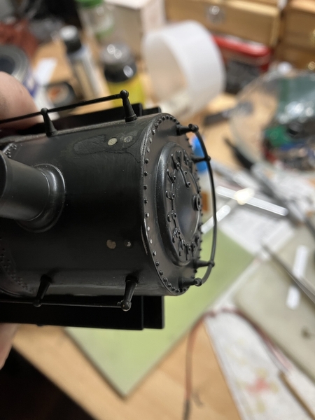
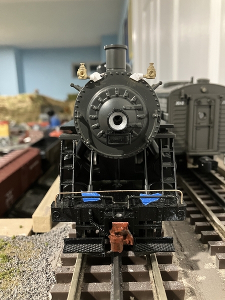
The marker lights on many New Haven engines were mounted on sheet metal or strap iron brackets that were riveted to the front of the smokebox, as opposed to holders on the smokebox sides. There are no brass castings (that I know of) that imitate this design, so I spent a while thinking of the best way to tackle it. I came up with a three piece solution: (1) a diamond cut out of sheet styrene to represent the sheet metal, (2) a piece of styrene tube with one side ground flat to glue to the styrene sheet, and (3) a brass caboose marker light with the sprue cut down to fit inside the styrene tube. Here are the parts laid out:
On the smokebox front, I sanded off two rivets equally spaced on each side to give a flat area for the brackets to glue to:
Brackets in place:
The next three photos show the marker lights themselves in place, along with all the front end details temporarily mounted to make sure I liked the look and nothing was too lopsided. A little lopsided is OK - this engine was nearing 40 years old at the time period I want to represent it, so a crooked detail or two speaks to that age. The firebox modifications, shorter steam dome (now painted), and whistle can also be seen:
Aside from some miscellaneous pipes I have to add back over the firebox area, this completes all the details I had in mind.
I'm considering representing the power conduit from the headlight over the smokebox front, but as the headlight and headlight bracket will be mounted last (long after paint, decals, and clear coating) I need to figure out how I would add it without risking damaging it or ruining the paint.
~Chris
Attachments
As always Chris, your work is exemplary. I look forward to seeing you run this at the summer gathering. Bill
Chris- Just perused your build thread. Very impressive work.
Bob
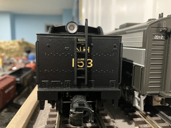
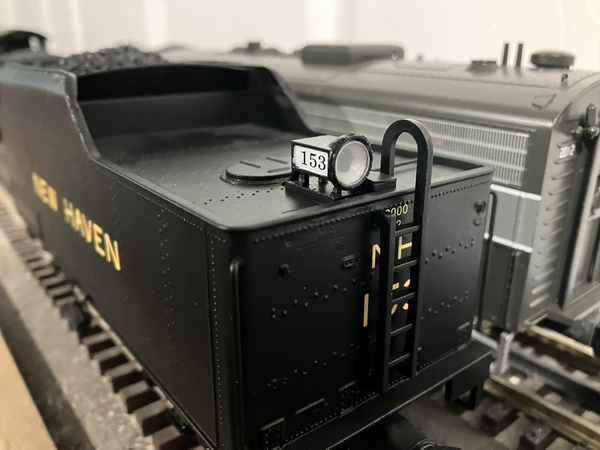
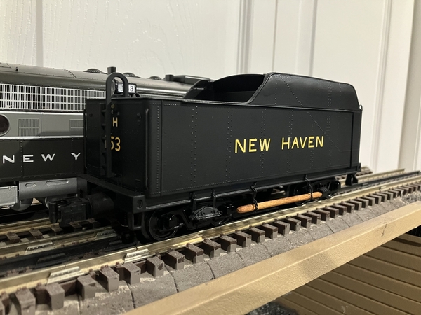
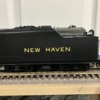
I completed the tender today. After applying the rivet decals, two more coats of Tru Color black were applied to seal them in. Text decals are from Microscale, which still produces their New Haven Steam Locomotives set in O-scale. I clear coated first Tru Color Flat Clear (to seal the decals, same brand and paint type as the black) and then with Tamiya TS-80 for a more dulled flat finish.
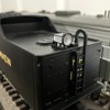
The headlight lens is a Lionel postwar reproduction of just the right diameter - a thin layer of white glue around the edge holds it in place well. I designed the headlight to accept a 3 mm LED from the rear. Inside the tender is the Blunami board seen in previous posts. The tender shell is isolated from the frame on this model, so signal reception to the board is excellent.
~Chris
Attachments
Looking good. Where are you sourcing your rivet decals?
I used Archer decals on this project. Majority of the tender rivets were from their "Railcar rivets (7/8 inch diameter)" set, using the already offset columns on the right hand side of the sheet.
No photos this post, but I put the first coat of primer on the boiler and pilot tonight.
~Chris
Thanks! Very helpful.
Well Young Man, It looks like we will be seeing this engine running at the summer gathering. It will look great hauling cars around the layout. Bill


