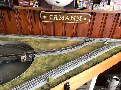
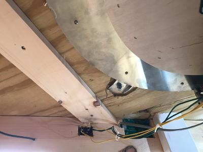
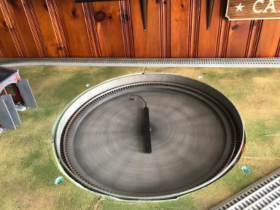
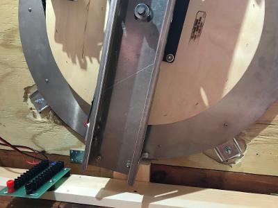
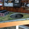
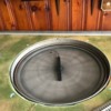
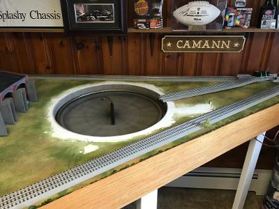
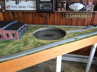
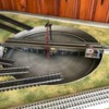
I'm in the process of installing a new 24" MR Turntable into my layout. The underneath mounting tabs (four) are 1.5" from the top of the pit wall. Unfortunately, for different reasons, I had to use 3/4" plywood and 1" foamboard to construct the layout - for a total layout thickness of 1.75".

That means if I just installed the turntable as is, the pit wall would be a 1/4" lower than the surrounding layout, which is unacceptable. I would want the pit wall height to be flush with the layout surface.

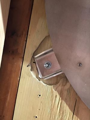
For a variety of reasons, it's not really feasible to cut the foam surrounding the TT lower by a 1/4" to make it flush with the pit wall. My thought was to first insert the TT into the layout from below so that the mounting tabs are flush with the bottom of the plywood and then trace out where the 4 mounting tabs are located; remove the TT; and then use a router to rout out where the tabs would go by a 1/4" deep, so that the tabs would be recessed into the plywood by a 1/4" and the top of the pit wall would then be flush with the layout surface. 

The tabs stick out about 2" from the  edge of the TT, so I could also rout out a full 1/4" deep 2" wide circle, but I think that's overkill. 

I just want to be sure I've thought this out or if there might be a different/better/easier way to make the pit wall flush with the layout surface.

All thoughts appreciated.

Last edited by Richie C.
Original Post

Replies sorted oldest to newest

well my first thought is remove that 1" thick foam sheet and use a 1/4" foam. it might be helpful if you could post a photo of area so others can see area as it is now and come up with a plan to help you. other thought is to replace that 3/4 plywood with a 1/2" piece best I can offer others may have better choices for you.

@StPaul posted:

well my first thought is remove that 1" thick foam sheet and use a 1/4" foam. it might be helpful if you could post a photo of area so others can see area as it is now and come up with a plan to help you. other thought is to replace that 3/4 plywood with a 1/2" piece best I can offer others may have better choices for you.

Thanks - like I said, there were other considerations that had to be first taken into account in arriving at the use of 3/4" plywood and 1" foam in building this part of the layout and the "given" is that it cannot be changed - no how, no way. 

The only question is how best to work around the 1.5" versus 1.75" differential and recessing the TT mounting tab locations by 1/4" deep seems to be a viable solution - just seeing if anyone on the Forum might have a different take on it.

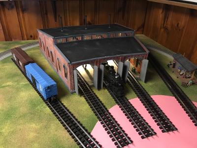
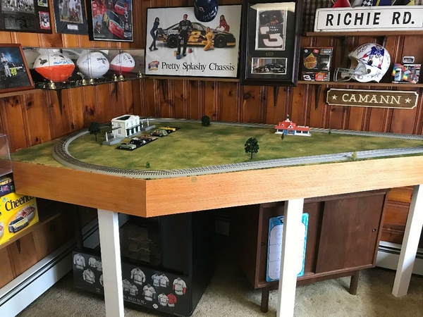
Pics of pre and post Roundhouse installation - the pink circle is approximately where the TT will go.

RH INSTALL 2

EXTENSION - FINAL 8

Attachments

Images (2)
  • EXTENSION - FINAL 8
  • RH INSTALL 2

Using a router on the underside of the layout to get your 1/4" will be a little messy but totally could be done.  That is the way I would go, although feel free to consider reinforcing the area after you mill some meat out of it.  

Otherwise, re-examine why not changing the top is a given.  The peninsula you are working on has a nice surface finish but no other significant details at this point.

jhz563 - That section of the layout mates up with a long straight run on existing shelving that is built into the walls and I had to build this section a total of 1.75" thick in order to mate up properly. How it all comes together through closets and from another section of the layout is complicated and more than I need to get into here, but trust me, it cannot be changed.

I agree that routing it out will be messy, but it is viable and I plan on adding some additional bracing once installed. 

Dr. Jack - I considered using the Ross TT but had to reject it because, since my TT has to be mounted into the decreasing radius "throat" area of a reversing loop, I did not have the width necessary to mount the Ross TT.  I only have about 30" width and the 24" Millhouse River TT fits nicely into that dimension.  


So... you're going to have to cut a 2 foot hole in the table anyways. 

If it were me, I'd mount it flush to the bottom of the plywood. Trace the tracks in the top, rout 1/4" deep grooves in the foam top and sink the tracks into the foam top. This will land your ground level roughly even with the tops of the ties. You can ballast in the grooves, which would leave you with an appropriate look for yard trackage. Similarly, rout out around the TT pit so the walls are level, and use a stanley sureform or some low number sand paper to contour the edges of what you contoured back up to the base level and do some scenery.

Exactly .... that is a good suggestion and the other option, i.e, contouring the foam top to have everything match up to the TT. My only concern with that is two-fold:

1. By the time I get through routing/cutting out a 1/4" deep  X  2.5" wide trough for 5-6 whisker tracks, it's just as easy (maybe easier) to rout out four (4) of the tab mounts which are only about 2" square each in the plywood underneath and then I don't have to worry about the pit wall height still being too low to the layout surface; and

2. I'm not sure how contouring the foam around the edges of the pit wall will come out looking. I realize it's only a 1/4", but to me, it wuld look unrealistic and a bit like a sinkhole. 

I'm going think about a way to improve that, though - thanks.

Cut a larger hole. Then place a 1/2 in. piece of ply on top overlapping the existing hole. Now cut your 24 in. hole in that and mount! Problem solved. Been there did it and it works great. By doing this you have raised your benchwork 3/4 inch. You will now need to use thinner foam but it essentially gives you the 3/4 inch of the benchwork back. I used 1/2 inch plywood and 1/2 inch foam on top. Now turntable mounts thru 1 inch and you can use bolts with nuts or washers as they suggest to adjust turntable flush!

Curtis

Last edited by CurtisH

Richie:

Probably not going to like these ideas unless you plan on keeping the turn table 'forever'.

1. If you can find someone - have them remove the mounting tabs and reattach lower or on the bottom of the turn table or

2. Remove the tabs completely. Screw a plywood 'bottom plate' under the hole in the layout, cut out a round 'shim' from 1/4 plywood and glue the turn table in place.

Thanks for all the tips and suggestions. I did originally ask Al about lowering the mounting points for the tabs by 3/8" so the top of the pit wall would be even with my layout surface, but he said it wasn't realistically possible and, in looking at the TT construction and welds, I can see that he was right.

I decided to go with routing out the tab areas in the plywood base as the best solution for my existing layout. I tried using a router bit and nosepiece for my Dremel but it was very slow and just not powerful enough to get the job done, so I purchased a Bosch palm router at Lowes along with a 3/8" wide straight bit and that was just the ticket.

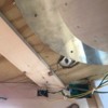
I temporarily screwed the TT in place and traced out the tabs and then took out the TT. I then used the palm router set at 5/16" depth to rout out all around the tab areas. I did it in one pass and only took about two minutes or less per tab, but what a sawdust storm. I had to go outside after each tab was done and have my wife turn the leaf blower on me to get everything off and clean-up was a b***h - both the layout and me !

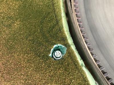
The routed tab areas came out very clean and smooth. I had to use some cardboard shims under one tab to make the TT pit wall level with the layout. After routing out the tab areas, I jacked the TT up into place with a bottle jack and drilled out the mounting holes through the tabs up through the foam. Since the heads of the bolts and washers are wider than the mounting holes themselves, I used a 5/8" spade bit to open a wider hole in just the foam to accept them and then dropped the bolts and washers down into place. My wife was gracious enough to hold the bolt heads in place with a wrench from the top while I added a washer and tightened the nuts from below and sealed with blue threadlocker.

I'll go back and fill the bolt holes in the foam and any gaps around the edge of the TT pit wall with vinyl spackling compound and cover with turf.

Next step will be to assemble, paint and weather the arch, cab and fencing for the bridge.


TT - 1TT - 2TT - BOLT HOLESTT - TABSTT - SHIMS

Attachments

Images (5)
  • TT - 1
  • TT - 2
  • TT - BOLT HOLES
  • TT - TABS
  • TT - SHIMS

Got the TT roughed in with a combination of Great Stuff and vinyl joint compound to fill the gap around the edge of the pit wall (sanded smooth); fill the holes where the bolts went in;  and to smooth out the transition of the whisker tracks to the TT. Then painted everything earth brown and covered with fine turf to match the surrounding layout.

I also hooked up the power and made sure everything was working correctly (works great) and am in the process of completing

and installing the arch, cab, bogies and railings and also mocked up the lead-in track.


TT - ROUGHED INTT - TURFED


Attachments

Images (2)
  • TT - ROUGHED IN
  • TT - TURFED

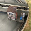
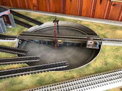
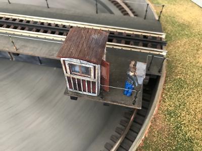
Finally got the bridge done - arch, cab, bogies and railings all assembled, weathered and installed. I also lightly weathered the bottom part of the bridge itself. There is a cabinet, control handles and an additional figure inside the cab and it is lit with an LED light. I'll post close-ups of everything when the project is completed.

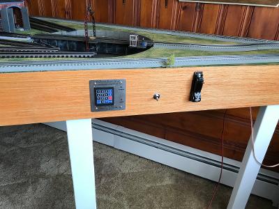
I also installed a new Lionel remote switch in the main for the lead-in track to the TT and then connected Fastrack pieces from the switch up to the TT. The height of the Fastrack on the layout surface was only a little taller than the height of the Atlas track on the bridge. I drilled and chamfered two new holes near the end of the Fastrack close to the bridge and screwed two screws down into the layout ( I used two flat head wood screws from Lowes that were #8 X 2.5") and that was enough to bring the height of the Fastrack rails perfectly flush with the bridge track. I lightly weathered the FT and darkened the center rail to match the Atlas bridge track and Gargarves phantom track I will be using for the whisker tracks. I mounted the remote controller for the switch onto the side of the layout.

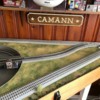
I then mounted the Millhouse River keypad and silver mounting plate to the side of the layout using a drill and scroll saw to carefully cut out the dimensions of the circuit board on the back and inserting that into the edging and then mounting the plate to the edging with nice brass screws. 

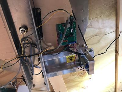
The TT works off a 12v wallwart that runs from the wall outlet to a circuit board on the underside of the TT using a barrel connector. Once you plug in the barrel connector underneath the layout, the light on the keypad and power to the TT is always on. I wanted to be able to easily shut off power to the TT when not in use w/o having to crawl under the layout to unplug/plug the connector in and out every time, so I decided to put a lighted 12v switch into the wiring that I could use to turn it on/off. I could have just cut the wallwart wire somewhere between the wall plug and the barrel connector and spliced the switch in , but I had these neat male/female barrel connectors with wire attachments in my parts bin which allowed me to not have to cut the wire. The female end simply plugged into the existing wallwart male barrel connector; then two wires from it to the switch; then two wires from the switch to the male connector; and then to the board. A little soldering needed, but a neat way to do it.

 https://www.amazon.com/Female-...1662928230&psc=1

I then mounted the lighted switch to the side of the layout edging and now I can turn the power to the TT on/off very easily. Since it's only 12v power to the TT and the lighted switch is rated for 12v, I didn't need to use a diode/resistor as I will need to for the whisker tracks which use 18v. Finally, I started laying out the location of some of the whisker tracks - unfortunately, the height of the Gargraves track on the layout surface is about 1/4" lower than the bridge track height, so I have some 1/4" foam roadbed on order to raise it up. In the meantime, I still have plenty to do, like permanently hooking up track power to a distribution panel so it's available for the TT and the whisker tracks. 

One of the nice features of the MR Turntable is that you don't have to lay out the whisker tracks in any kind of spacing or separations or angles. You can lay out the whisker tracks anywhere you want and the TT indexing system will line the bridge up to wherever that track is placed on the layout.
TT - BRIDGE COMPLETEDTT - CABTT - LEAD IN TRACKTT - SWITCH WIRINGTT - SWITCH WIRING 2TT - SWITCH 1


Attachments

Images (6)
  • TT - BRIDGE COMPLETED
  • TT - CAB
  • TT - LEAD IN TRACK
  • TT - SWITCH WIRING
  • TT - SWITCH WIRING 2
  • TT - SWITCH 1

Add Reply

Post

OGR Publishing, Inc., 1310 Eastside Centre Ct, Suite 6, Mountain Home, AR 72653
800-980-OGRR (6477)
www.ogaugerr.com

×
×
×
×
Link copied to your clipboard.
×
×