John, thank you for the link. I saw those and wondered about the quality of them. The screw holes for mounting are a great feature.
Mark, I wanted to get your thoughts on these.
@John H posted:Here is a good thread on different styles of Wago and Wago-like connectors that have tabs for screw mounting. There are also ones with A and B inputs. I just got some of those, very useful. I wish I had them from the getgo.
Mike, Take a look at the thread John H linked above. In the last two posts on that topic, Mr. Mouthpear cites he likes the very thing you found. There is also information and opinions on this link OGR thread
Morning Mark, thats how I found them. From your wonderful thread that everyone is adding to!
Yes Mike, I'll take his word that they are reliable. I like the little tabs with holes for mounting them.
Because you have to push the wire in fairly hard on the non-lever connectors to secure them in place, I've read that when using stranded wire, the wire can come apart and this can be an issue, so it would appear that using the lever connectors, especially with the screw holes is the way to go.
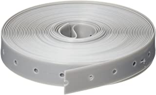
As far as using clips to hold wires and connectors in place under the layout, I've taken to using what is known as "plumber's strap tape" which is used by plumbers to secure/hang pipe. Using wire or cable clips can be difficult when you're on your back and need three hands to hold everything in place or drill a starter screw hole or have to use a hammer to drive a clip in place which dislodges everything on the top of the layout.
The plumber's tape is a semi-rigid plastic tape about 3/4" wide and comes in rolls of different lengths. Depending on how many wires I have to hold in place or how heavy they are, I usually cut a 1.5"-2" section of tape off the roll with a scissors and then crawl under the layout and position the plastic tape over the wires, straddling them in place, and then staple each end of the tape to the underside of the layout with a heavy duty staple gun - an electric staple gun makes the job even easier. In fact, the tape is stiff enough that, for most applications, you only need to staple one side in place and it will hold the wire(s) in place just fine. One advantage to that is that, if you ever need to run another wire nearby, you can just lift the unstapled end of the tape up and slip the new wire underneath and either continue to leave that end of the tape unstapled or staple it if the wires are too heavy.
If you have a long run of wire, you can just add a section of tape along the run wherever needed. The tape and gray color are also useful to secure wires that you're trying to hide.
In addition, a small roll costing less than $5 goes a long way.
Attachments
The reason I am looking at the pass threw ones is I am like Rick, My control panel is in the middle so I did a bus wire all the way around and have really never had a problem with DCS Signal. This way I can power in one side and just keep going out the other side!
Richie, Thank you for the information on the non-lever ones being problematic on stranded wire. The plumbers tape is a great idea. Thank you again for your input!!
Last night I ordered a variety of 2, 3 and 5 port wago connectors, cable tie/supports and a variety of 3M foam double sided tape pieces. I am also expecting the tvs's and psx-ac's to come soon. I will have lot's of projects to choose from when I'm off during Christmas and New Year's! Thanks for all the input in this discussion. It has solidified a lot of loose ends that were floating in my mind for the layout wiring. Hope everyone here has a Merry Christmas and a blessed New Year!
Michael
Michael, I am glad you were provided with lots of new projects because you contributed to this topic discussion!! ![]() Have a Merry Christmas too!
Have a Merry Christmas too!
Merry Christmas, everyone!
Merry Christmas all!
Merry Christmas Everyone!
Mark, can you PM me and let me know where you order from?
Back atcha, Mark and Mike. Merry Christmas!
Yesterday Mike sent me a PM asking why I was getting 5-port Wago connectors. My answer was that I did not see that 4-port ones are available. Well he found some, but my order was already in. So today I received a box of 5-port Wago connectors, 50 TVS's (that should be more than enough), and a linear actuator like Mike used to raise and lower his bridges. All I am waiting on are the limit switches for the bridges and the cable clamps. I already have the toggle switches. I told Mike I will post photographs of how I add the TVS's to the drops and feeds to the panel. That will be the first project.
The panel! Yes, that is something I wasn't going to bother with, since I have 2 AIUs on order for switch control. I'll need something for the toggle switches to cut power to the sidings, something I forgot about until I started connecting the mainline feeds. I forget a lot. I have plenty of Masonite to use. I wasn't thinking of putting a track plan on it, but I'll have to label the switchers in some way. Maybe I will end up with the track plan.
Hey Mark, I took my track plan to the local printer and he printed it on self adhesive vinyl!
Mike, that was a great idea!!! Thank you!!
I have received all the parts I think I need for the TVS installation and the bridge lift installation. I bought a small piece of really nice 5/8" 7-ply plywood to cut for the bridge and actuator supports as well.
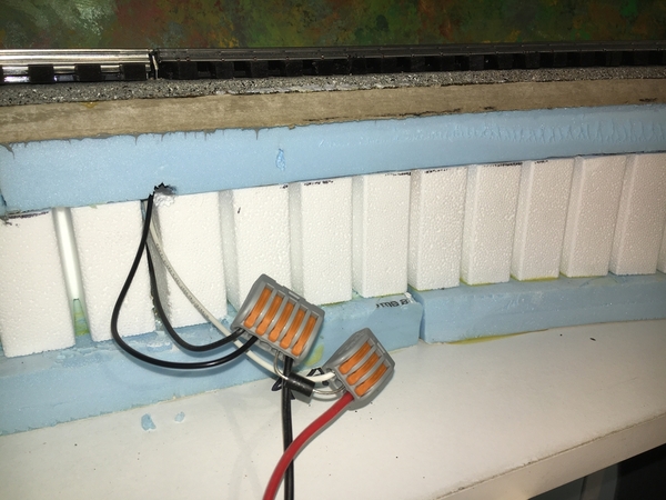
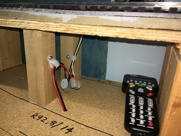
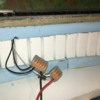
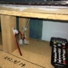
Here are a couple of photographs showing the connectors with track feed wires, TVS, and larger wires back to the panel area, as requested by Mike. This one is the best to show what I am doing which is what Michael drew. The white background makes things show well. This was before I put in the cable clamp to hold it from me snagging the wires.
Tis is showing an upper level feed since it is easiest to get in and take a photograph. This one is a single track connection with the white wire from the center rail going to the 3-port connector, the TVS is a bit hard to see on the center port of the connector going to the center port of the 5-port connector. The two black wires from the top are to the outer rails and go to the 5-port connector. The red wire is on the 3-port connector and the large black wire is on the 5-port connector.
On to the ones under the layout!! ![]()
Attachments
Looks good Mark, you sure make it look easy, I will have to do some testing when I get mine before I hook it up to the layout. But now I know how it is to look!
Mark how and where are you installing the TVS diodes? It appears to me you are installing one at every drop where you tie into your main buss wires!
Rick, yes that is right, but it’s not a main bus. It’s just the closest point to the track on each feed of the DCS star wiring.
Mark, Excellent use of Wago connectors.
Steve
Moving right along! I had a bunch of 3M scotchlock connectors that I used (really just because I had them). They're easy to use when you're standing or sitting somewhere comfortable, not so much crouched under the table with arms overhead. Although it got easier after the first few.
If I had to do it again, I'd use the lever connectors like you are.
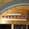
My control panel with toggle switches is just a few printed sheets of paper pasted to a 1/8" x 12" x 24" plywood board. Drilled holes right through the paper and board and stuck the toggles in. I liked the idea of a nice printed one on vinyl, but it felt a bit too permanent if we wanted to mark up or make changes later, just print new paper.
Looking great!
good idea installing tvs diode's even if it saves one ps 2 3 volt or ps 3 boards it was worth the effort, the only inconvenience is if one shorts you'll have to disconnect them all to find the shorted one but other then that it's a great idea and can save you a lot of money!
Alan
P.S. hope you had a very Merry Christmas you and your trains wife and family!
Alan Mancus
Mark, I have a concern. IIRC from a discussion here TVS diodes can and do fail, sometimes open and sometimes closed. The only assurance against a failed open is periodic replacement (because no way to test for an open) and of course failed closed is a direct short-circuit. I wouldn't have them anyplace inaccessible.
Mike, Rick, Steve, Jeff, Alan, Lew, Thank you for all the great comments, observations, and questions!
Steve, thank you. After seeing folks post photographs of connectors that have mounting holes, I started to question my use of these slightly hanging in mid air. While a couple of installations closest to the wall underneath the layout were a bit awkward to make, I still think I won't snag any of the ones closer to the aisle when storing items.
Jeff, I have used the Scotch Lock kind in the past and agree these are so much easier to use. They hold well even as I tugged as hard as I could to pull the wire and even the TVS leads out. Your use of just printing the track plan on paper that can be printed again for changes does have merit. If you placed a clear plastic sheet over it before drilling, it would be a similar end result to Mike's panel. So many ways of doing things.
Alan and Lew, you are both right there is a problem if a TVS shorts out or opens up. Periodic replacement is a good point I hadn't thought of.
As to the suggestion to not place any that will be in an inaccessible area, that is something I already thought of. I posted once on this topic way back (Next month will mark 4 years since I started the topic) that I plan to build scenery sections on the workbench, then place them on the layout. Anything that covers something up, will be removable much like Bruce G. and others have shown. Where is the workbench, you may ask? Well, for now it is one of the shelves under the layout that works well with my padded stool as long as it is a project that has little height and I won't sit very long. I can set up the narrow folding table that I used building a couple kits last winter and slide it in and out from a section of the layout that doesn't have a shelf. I have no room for a permanent workbench in this house. ![]() I setup horses on the patio and now in bad weather in the garage stall if I pull my wife's car out.
I setup horses on the patio and now in bad weather in the garage stall if I pull my wife's car out.
Troubleshooting a shorted TVS or any other short circuit got me thinking. I have the toggle switches that I am going to wire into the feeds to all the sidings to shut off power when I want to park an engine. I already wired in the mainline sections without power switches. Alan and Lew, you got me thinking this morning (Smell the smoke??) that I should add toggle switches to all the track feeds. It would be so much easier to throw toggle switches to find a short circuit than lifting wires on the terminal block on the board I showed a couple weeks ago.
Thank you again, one and all!! ![]()
![]()
Glad to see you truckin' along Mark!
Attachments
Mark,
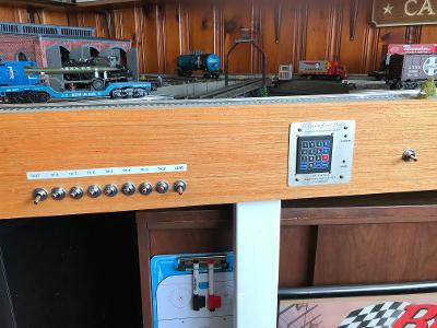
An inexpensive label maker (I got mine at Staples) is a good way to label your main switches. I also found it helpful in labeling other
switches and toggles around the layout.
Attachments
@Mark Boyce posted:Troubleshooting a shorted TVS or any other short circuit got me thinking. I have the toggle switches that I am going to wire into the feeds to all the sidings to shut off power when I want to park an engine. I already wired in the mainline sections without power switches. Alan and Lew, you got me thinking this morning (Smell the smoke??) that I should add toggle switches to all the track feeds. It would be so much easier to throw toggle switches to find a short circuit than lifting wires on the terminal block on the board I showed a couple weeks ago.Thank you again, one and all!!

Mark- If the track sections are not isolated from each other, you won't be able to achieve what you want with the switches on the mains. I'm not familiar with the TVS's, but wouldn't the short just carry through the track thus rendering the switches useless?
I'm not familiar with DCS either so maybe one of the experts can weigh in.
Bob
Richie, Those labels look great! We had label makers that made labels like that at work. When cleaning out my parents' house I found one of the old Dymo label makers that you turn the dial to the letter, then squeeze the handle to make the embossed label. Dad probably brought it home from work after they bought the ones they have these days. The labels I made with it still stick good. I made a lot of labels with that kind myself years ago.
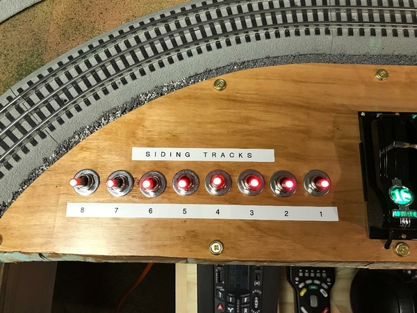
That brings up a good point. Since I am planning to control the switches and eventually a few accessories with an AIU, I will only be putting the toggle switches for track power on a panel. I'm still thinking I may just line up labeled switches in a row or two like you showed, Richie.
@RSJB18 posted:Mark- If the track sections are not isolated from each other, you won't be able to achieve what you want with the switches on the mains. I'm not familiar with the TVS's, but wouldn't the short just carry through the track thus rendering the switches useless?
I'm not familiar with DCS either so maybe one of the experts can weigh in.Bob
Bob, I have isolated gaps between all the mainline blocks like on the sidings. I think there are 8 of them. That was a carryover from old HO conventional days, wiring for two train operation.
@Mark Boyce posted:Bob, I have isolated gaps between all the mainline blocks like on the sidings. I think there are 8 of them. That was a carryover from old HO conventional days, wiring for two train operation.
My first thought when I read your post was wonder if he has each section isolated from the next.
Should have known better......
now returning to your regularly scheduled program.....![]()
WOW, now I have to make sure I have blocks, or I will be chasing shorts for ever! LOL
Bob, You never know! There are so many ways to do things. Of course some ways are better than others, and some ways are just different.
Mike, If you have a basic Dremel tool with a cutoff wheel, just cut the center rail at logical spots, and you are in business. Some folks put in insulated track joiners when they lay track, and some people put in pieces of styrene or something else and file to the shape of the rail. And then there are some who have still just left the air gap. I'm in the latter camp. ![]() I should put in the piece of plastic, but this layout is still under construction.
I should put in the piece of plastic, but this layout is still under construction. ![]()
@Michael Cimba 040217 posted:Mark,
I did this layout sketch of the way I think you are doing your track wiring. Is this correct?
I will probably follow your lead and do the same method. Those wago connectors are pretty sweet. What cable clips did you order to secure your installation? I would want everything secure and not hanging loose. Was wondering if you could use double stick pressure tape to secure the wago connectors to the under side of the table?
In addition to the wago connectors do you have a "t" type or suitcase connector you like for bus type wiring?
Thanks for letting us all piggyback off of your methods 😁!
My layout is already wired and was wondering how to add the TVSs close to the track, like most recommend. I was thinking something like this, but was not sure if it would work. Glad to know it will and I use the WAGO connectors all over my layout. I was not sure if cutting the wire, near the tack, from the terminal block and adding the TVS and the WAGO connector would hurt my DCS signal.
If you use Ross Switches, there is a natural break in the center rail at the switch. I end most of my blocks at switches.
@Tony H posted:My layout is already wired and was wondering how to add the TVSs close to the track, like most recommend. I was thinking something like this, but was not sure if it would work. Glad to know it will and I use the WAGO connectors all over my layout. I was not sure if cutting the wire, near the tack, from the terminal block and adding the TVS and the WAGO connector would hurt my DCS signal.
Tony, I tested for signal strength after adding the PSX-AC1 and WAGO connector and got 10. I just did the same on a block with the WAGO and TVS and still got 10. My runs are relatively short in an 11x11 room, so I don't know if the signal would drop if on a longer run.
@Pat Kn posted:If you use Ross Switches, there is a natural break in the center rail at the switch. I end most of my blocks at switches.
Pat, that is a very good point. Are your switches the regular Ross or the Ross-Ready with the jumpers on the bottom?


