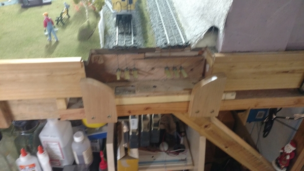
Nice job Mark. If I may make one suggestion, attach your Tiu and aiu with velcro. Much easier to remove if you need to upgrade or move. Art
Thank you Leandro, Mallard, and Art.
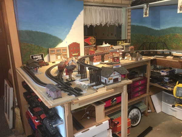
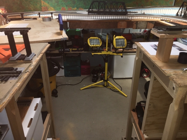
Mallard, that is an excellent question. I just tested it out and it is possible to bang a knee on a shelf corner, but not probable. The layout top overhangs the shelves by a few inches. The second shelf comes right to the top of my knee. I had to push my stomach up into the table and awkwardly bend my knee for it to hit just at the top of the knee. Once I have the fascia on the layout and the lift up bridges in place, I think there will be even less chance of bumping. Excellent question and concern!
Art, I tried some Velcro before on the TIU, but what I had didn't stick well enough to the surfaces for the weight of the TIU. Of course I know there is better Velcro available with better sticky. It is a very good suggestion. Thank you.
@Mallard4468 posted:Such nice, neat wiring. I should be paying attention.
Nice use of "wasted" space for the shelves. One question / observation - do the ends of the shelves in the foreground pose a risk of being hit by a wayward knee?
Great Northern at the Blackwater Canyon Line! I like it! But, I would, wouldn't I?
@John C. posted:Great Northern at the Blackwater Canyon Line! I like it! But, I would, wouldn't I?
John, I knew you would like it. I love the colors of the Great Northern. Actually those two GP7s were a deal I couldn't pass up. A Western Pennsylvania Hobby Shop had them at last November's Monroeville Greenberg show. I have purchased from them before. I saw these two with a tag $150 for the pair, so I wondered what is wrong with them. I saw there were some cosmetic defects, but nothing that couldn't be taken care of. One has Legacy and the other is nonpowered. The Legacy one ran great on the test track, so I bought them. $30 worth of parts from Lionel and everything is replaced except I still need a bell for one. I never saw GP7s with bells. There is still some minor paint wear on some corners, but that is it. I already have a Legacy GP7 in Western Maryland Speedletter scheme. It has been suggested I repaint these in the 1970s Western Maryland red-white-black colors, but I like them as they are.
Yesterday, I did some preliminary work on putting in the mike g. lift bridges by removing the wood lips and alignment screws that held the lift out section in place. I also did a bunch of measuring and drawing to figure what to cut to build a similar arrangement as Mike's. Nothing much to photograph yet, but it is a start on the project.
Good deal. Those lift bridges will be awesome!
Also looking forward to lifts, I have yet to venture there on my layout
Thank you, Bill and Catdaddy. I'm just hoping I can do as well as mike g. who came up with this method.
One of my favorite on going threads!
Hi Mark, I have all the confidence you will do a great job with the bridges! Looking forward to your progress.
@MartyE posted:One of my favorite on going threads!
Marty, Thank you very much!!! I think this is a good time to comment on how much I appreciate all the comments and 'likes' from so many great folks! I recall 4 years ago DoubleDAZ Dave commenting in an email to me shortly after volunteering to help me with the design that some of these topics don't seem to gain much of a following and others do. I hoped this one would. I have truly been blessed by all of the encouraging comments, suggestions, corrections to my thinking, and even comments like, "Just build it!" when we were nit picking the earlier designs.
While I have had model trains since an early age like many of you, and have built other layouts, this is my first in O gauge 3-rail and my first using command control. I have received so much help and encouragement on the ins and outs of those 2 areas of the hobby. Also, I have been old school in choice of materials and methods of construction. Not that old school doesn't work anymore, but that there may be better and easier ways of doing things considering I still use basic power tools.
@Aegis21 posted:Hi Mark, I have all the confidence you will do a great job with the bridges! Looking forward to your progress.
Thank you, John!! I'm sure I will get it working too, I may take a few steps back in the process however. ![]() I still need to come up with the second bridge. I have an Atlas through truss bridge that I bought from another Forum member that still needs some minor repair of the very delicate webbing. He did a good job packing, it is just that it is that delicate. I am hoping I can brace it enough underneath as Mike did on his.
I still need to come up with the second bridge. I have an Atlas through truss bridge that I bought from another Forum member that still needs some minor repair of the very delicate webbing. He did a good job packing, it is just that it is that delicate. I am hoping I can brace it enough underneath as Mike did on his.
Again, thank you everyone!
Ok, Ok Mark... Mark, Mark... Less typing, MORE Bridge photos. ![]()
![]()
Yea! What @Miggy said! I mean I'm being patient but hustle up!
Way to go Mark, the preparation always takes the most time.
Wow! That sure was fast! You layout looks like it's really going to be a joy to operate.
@BillYo414 posted:Yea! What @Miggy said! I mean I'm being patient but hustle up!
Bill, "and even comments like, "Just build it!" " ![]()
This weekend I made some progress on the mike g. lift bridge installation. There was a lot of trial and error, but here it is as of now.
The two bridges will settle to the down position on this end. I added a 1x2 to the Mianne legs so there would be something firm to attach the bottom board for the bridges to settle down on. The high bridge will have a pier to accept it.
I had to adjust the heights of my horizontal braces on this side several times to get it to work. The upright is attached with just a drywall screw for now at the pivot point to get it lined up right. It is just the first piece of the actual bridge support. I noticed I need to make some changes after I finished today.
Here it is in the down position with a through girder bridge section lettered for Western Maryland Railway balanced on top. I need to get two more through girder bridges to cross the chasm. I'll use the through truss bridge on the upper level so you can see both bridges well from wither side.
Attachments
I don't know why but I thought the span was a lot smaller. That's going to be an awesome scene!!
Thank you, Bill. The opening is actually 27 inches wide. The through girder bridges are 10 inches long, so three will take up 30 inches. The cutout on the right will let the right hand girder section flip down below table level. I plan to make an indent in the steep river banks to make it look like there was a reason for the bridges going that far. My Atlas through truss bridge is only 26 inches long, so I'll have to work out piers to make that look right.
Nice. I have always thought railroad bridges were the coolest. It's just such a great view!
Mark,
Looks great. A lot of tedious carpentry work. It will all be worth it to not have to crawl under. Ha!
John
Mark, thank you for keeping us informed as you move forward with your endeavor. Based upon your efforts I’m considering doing something along these lines for my pending construction.
Mark, great progress and when finished it’s going to be a neat focal point and it makes for a realistic scene. I like your backdrop scenes, your layout are is coming alive. Great work. I suspect your going to make it rise similar to a bascule bridge with an electric motor, good idea. Your post has 45 pages of fun. Oh, just for your knowledge, the Western Maryland GP was originally Dave Slies, he had said it was like new. Have fun on your engineering project. Happy Railroading, stay safe, stay healthy.
This week on Discovery Channel MEGA DISASTERS, Mark forgets he hasn't finished the lift bridge and runs his new engine...
Eastwood Ravine will never be the same.
Very nice Mark. ![]()
Mark really looking good. I need to pay closer attention to what you are building it is giving me ideas to consider change or modifying my track plan to include such a bridge as you are building. Watching you build this layout has been fun you do nice work. Keep it up.
fThank you Bill, John, Jay, Larry, Marty, Bob, Rick!!
John, as with most builders of layouts, the carpentry isn't the best by far, but who will notice when the bridges go down and trains run across them! You are right, I don't really care what it looks like as long as I can walk through, lower it, and trains run across.
Jay, It will sure beat crawling or even ducking under your layout!
Larry, the backdrop was painted for George (G3750) for his PRR Panhandle 1.0 layout. He chose to get photographic enlargements for his Panhandle 2.0 layout and offered them here for sale. Yes, it will operated something like the bascule bridge. I give mike g. all the credit for the idea. I saw his short video and realized he had a similar situation and I should be able to duplicate it with my tools and skills. Thank you for the note about the GP7!! It runs great and is on the shelf right now.
Marty, Mega Disaster for sure!! ![]() Last week I was running my most expensive engine that I am considering selling to help pay for more layout material. Testing all the features, I checked the DCS Info on the engine, and then started to move the thumbwheel to stop it from speed 8. No engine control while in Advanced\Info! Fortunately, I was only half way around, but it was a wakeup call, since I don't have the power killing interlock in place yet for bridge up!!
Last week I was running my most expensive engine that I am considering selling to help pay for more layout material. Testing all the features, I checked the DCS Info on the engine, and then started to move the thumbwheel to stop it from speed 8. No engine control while in Advanced\Info! Fortunately, I was only half way around, but it was a wakeup call, since I don't have the power killing interlock in place yet for bridge up!!
Rick, I wouldn't have done it if I wasn't building a walk-in layout. I wasn't that confident in my skills. However, some sort of movable bridge was planned for in the beginning, but I didn't know what until I got looking closer at what Mike had done.
Mark, things are looking good! I do want to point on one thing though, on the right hand side where the bridge deck lowers below the bench work you are going to bevel the end at a 45 degree angle to prevent binding. I will get out and take a photo this morning for you so you can see what I am talking about. You will have to do the same with your track also.
But I do want to say its nice to see it coming along nicely! When you get to the point of wiring the actuator let me know I have a couple hints to make things a little easier.
Mike, Thank you very much for all the help on this project! You hit on one thing I thought about when I was taking the photographs. I started off cutting the board that pivots up and down too long. Now I have taken too much off for a nice fit. If it fits right, then the ends have to be beveled both on the the board and the track. That's okay, I have a lot more material to cut from, and I'll still make use of this piece. Also, there are some cuts on the table that need trued up. As of right now, it is just the rough cuts from the drill and saw. My use of cutting tools wobble all over the place. ![]()
Some of my track joints aren't as tight as I would have liked either, but they haven't proven to be a cause for derailment. They just don't look that great, but I'm probably the only one who will notice.
Wiring the actuator was one thing I was thinking I will need to ask you about. I have several thoughts, and probably none of them are the easiest. ![]()
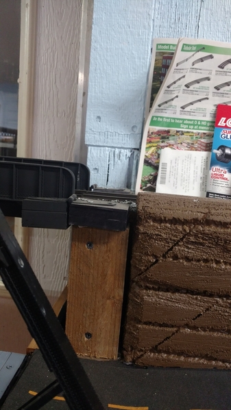
Hi Mark, here are a couple photos of the beveled ends. I have been looking at your photo and I have an idea on how to make it easier for you. since you have to still cut the board just cut it the total length then just cut 3 maybe 4 inches from the end that goes into your little cut out and you can just but that up against the square end you have there already. If you would like I can PM you my phone number and we can talk it over. I have nothing but time right now as I cant work out side due to all the rain.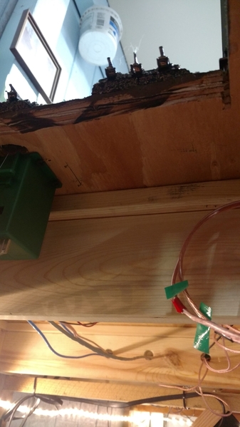


I have also included some photos of the hinges for the upper bridge. If you and make it where the hinges are the same height of the top if the rail of your track you don't have to bevel them they can stay square and just have a little gap. It doesn't have to be much.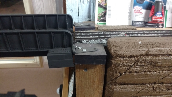
Attachments
Mike thanks for posting the photos. The bevel solves the alignment problem I was thinking about. Looks like the weight of the bridge provides a tight mate between the tracks at the hinge end. Do you have anything which acts like a guide to insure alignment? (wood tends to move over time) Jeff
Mike, Thank you for all the photographs and description. That is great how you have the track protruding a little bit from the stationary area and then matches up with the swinging section. I was thinking the upper bridge could just be hinged as you did. Painted black, the hinges just blend right into he bridge scene. That is also a nice 'notched' area on the opposite end for the bridge to seat into squarely.
Jeff, thank you for asking the question. As Mike said it is raining there, I was thinking, his wood never dries out since it always rains on the Washington Olympic Peninsula where he lives. Just kidding! ![]()
Speaking of rain. I am going to go out and shovel and snow blow some. I'll be back in for breaks. More snow on its way this afternoon and tonight. Those folks Down East sent their nor'easter here to share with us Western Pennsylvania folk. Right, Bob!! ![]()
Mark, Take it easy in the snow!
I did, Mike! Thank you for watching my back! I blew out our driveway and left the sidewalk shoveling for the next go round. Then I'll take a break and walk down the road about 100 yards to my mother-in-law's place and do one lane of her two lane driveway. She has never driven, so usually the only ones pulling in are my wife or me. She walks out to the mailbox, which is the biggest problem. She will not listen to us telling her to wait for us to bring in the mail. She stands or sits at the front window talking on the telephone all day long to see the few people that pass by or what the few neighbors are doing. We joke behind her back calling her Mrs. Kravitz from on Bewitched. ![]()
Mark, I am glad your taking it easy! You don't need to hurt yourself as the snow will melt one day! LOL I hope you took some time for yourself and had some soup or something. You know you will need your energy when you get back to your bridge project!
Speaking of rain. I am going to go out and shovel and snow blow some. I'll be back in for breaks. More snow on its way this afternoon and tonight. Those folks Down East sent their nor'easter here to share with us Western Pennsylvania folk. Right, Bob!! ![]()
Mark is was not just you we got 7 inches and it is still snowing not rcpecned to stop until tomorrow sometime before noon.
Thank you, Catdaddy! I wouldn’t mock at all! After 65 cold winters, I would welcome your winter!


