Originally Posted by Putnam Division:

That is one handsome bridge!


Peter

It certainly is.  At last Fall's York I had a serious discussion with the guys at East Coast Enterprises and they were very intrigued by the prototype.  I happen to think the prototype is one of the most beautiful railroad bridges in America.


IMG24


I think they captured the essence of the prototype in their model.  The real bridge, including approaches, is over 1,900 feet long.  Obviously you cannot reproduce the prototype as a scale model in 1:48.  That would be a bridge nearly 40' long, but the proportions are correct.


George

Attachments

Images (1)
  • IMG24
Last edited by G3750

Updated 5/18/2014:


I have started assembling the highway overpass at Crawford's Crossing.  Here's a look at the prototype (the highway between the mills circa 1957).


1957 Weirton Steel


Here's my start.  I have glued the edge of the roadbed (closest to the viewer) to the foundation layer of the highway.  The sidewalks are clamped down to help align the roadbed.  Eventually, they will be glued down followed by the roadbed itself.  After that, I will determine locations for the telephone poles, drill holes, and install them.  Finally, I will install the Crow River railings.  Pilings and piers to come after along with placement on the City of Weirton module.


DSCN0236


George

Attachments

Images (2)
  • 1957 Weirton Steel
  • DSCN0236

Updated 5/19/2014:


Got some more time tonight and managed to glue down the roadbed and both sets of sidewalks. The photos don't look much different from the previous post, but there is real progress being made.


DSCN0238


I added a foundational piece under the pointed end of the roadway. This will stiffen the overpass structure and keep the sidewalk properly aligned with the roadway. The end on the left side of the photo will be up against the against the wall.

DSCN0241


Here's another use of a Roget's Thesaurus.

DSCN0242


George

Attachments

Images (3)
  • DSCN0238
  • DSCN0241
  • DSCN0242
Originally Posted by G3750:
Originally Posted by Putnam Division:

That is one handsome bridge!


Peter

It certainly is.  At last Fall's York I had a serious discussion with the guys at East Coast Enterprises and they were very intrigued by the prototype.  I happen to think the prototype is one of the most beautiful railroad bridges in America.


I think they captured the essence of the prototype in their model.  The real bridge, including approaches, is over 1,900 feet long.  Obviously you cannot reproduce the prototype as a scale model in 1:48.  That would be a bridge nearly 40' long, but the proportions are correct.


George

I'll say they captured the essence of the bridge.  I love bridges like this.  This is the first I have seen your thread.  Very impressive work!

Updated 7/19/2014:


Ordered and received a set of 4 working traffic lights, controller, and power supply from Greg Leonard.  Testing is in progress.  The lights look absolutely spectacular!  Traffic light positions are indicated by the RED dots.  Each is a single-facing Red-Yellow-Green traffic light.


image002.jpg


Main Street (the long horizontal road) will have 2 signals.  Clockwise is Country Road and then Pennsylvania Avenue. 


George

Updated 8/16/2014:


Major changes are coming to the PRR Panhandle!


  • Last week, I placed the order for the Steubenville bridge from East Coast Enterprises.  We are scheduled for pickup at Fall York.
  • I have started planning the construction of the new bridge's piers.
  • Today, I removed the Curtis Double Cross-over in preparation for mailing it to its new home. 
  • I also documented the new train movements that will be needed to switch Weirton Steel and Standard Slag without the use of the cross-over.

In the next week or so, I will update the track plan and the front page of this thread.


George


Updated 8/20/2014:


Awhile ago I ordered 1:48 traffic lights from Greg Leonard.  They are fabulous!!!!


http://miniature-traffic-lights.com/testimonials


They have arrived and I finally got them on the bench for testing.  In the diagram below, the lights are assigned to the streets (clockwise) - County Road, Pennsylvania Avenue, Main Street (South), and Main Street (North).


image002.jpg

Here's a video of them in operation.


Needless to say, I am very pleased with how they look and operate.


George

Attachments

Videos (1)
DSCN0434
Last edited by G3750

Updated 8/28/2014:


In honor of the 2014 Steel Mill Modelers Meet, I am posting some steel related photos from the past.


Lionel slag cars dumping their loads at Standard Slag

DSCN0028


My scratchbuilt ingots on my scratchbuilt ingot cars.  Hot, don't touch!

Ingot Cars 2


Open Hearth with ingot cars exiting the front and WSX Alco S-2 #208 entering the side.

SAM_0390W


Lionel Alco S-2 (formerly Western Pacific) now sporting Weirton Steel green (c. 1946).

WSX 208 & Ingot Cars 001


WSX #208 with ingot cars.

Updated slag cars 009


"Mr. DeMille, I'm ready for my close-up".  Great paint job by Tommy Gilbert.

Updated slag cars 001


The Weirton Steel Blooming Mill

Blooming_Mill_04_


George

Attachments

Images (7)
  • DSCN0028
  • Ingot Cars 2
  • SAM_0390W
  • WSX 208 & Ingot Cars 001
  • Updated slag cars 009
  • Updated slag cars 001
  • Blooming_Mill_04_

Updated 9/3/2014:

i got this poster awhile ago, maybe 2-3 years back at a train show. I can't even remember where - might have been the O Scale show at Strasburg. Last night I was looking through my e-mail and realized I had a 40% discount coupon for AC Moore and that they had a bunch of frames on sale. Now usually, the stuff I have for framing is an odd size and requires some custom (read expensive) frame. I measured the poster and went to the store today. Here's the result - instant education for train runners!


PRR_Rules_01_


George

Attachments

Images (1)
  • PRR_Rules_01_

I guess this post could be called "Bad kitty visits the PRR Panhandle". 


Her Orangeness, Pumpkin, decided to assert her authority over her domain in a visit this morning.  Fortunately, the camera was nearby.


Pumpkin_Visits_01_


Here she inspects one of my scratch-built ingot cars.  She's inscrutable, so I have no idea what she thinks of it.


Pumpkin_Visits_03_


If you ever doubted it, the old saying is true:


Dogs have owners; cats have staff.


George


Attachments

Images (2)
  • Pumpkin_Visits_01_
  • Pumpkin_Visits_03_

Updated 9/13/2014:


I have spent the past 3 days working out the dimensions of the model bridge piers.  Because of space limitations, the dimensions are not and can not be 1:48 scale with the prototype.  They will actually be somewhere in the 75% of O scale, but will retain  accurate proportions to themselves and to the bridge model.  Below are three photos centered on the piers followed by a dimensional drawing of the model.


First, a distance shot from the Ohio side of the river.  Interestingly enough, there are no debris deflectors on the bridge.  Upstream is to the left; downstream to the right.


DSCN0158


Here you can see the "rings" on the pier.  Each is 3' high and made of poured concrete.  There is also a good view of the left bridge foot (really massive).

DSCN0157


Finally through the dappled sunlight, we can see the railings, the bridge feet, handrails, and the red navigational warning beacon at the top of each pier.  The Ohio River sees a substantial amount of towboat / barge traffic.


DSCN0155


This is my selectively compressed drawing of the bridge pier. 


Bridge Piers v004


The thinking is to make a longitudinal slice (split halfway down its height) of pier out of pink foam.  The foam will be sealed with joint compound and sanded.  Lines for the rings will be scribed into it.  The "positive" will be used to make a mold.  Halves will be cast using the mold with channels for the beacon light wires cut in the halves.  The halves will be glued together, sealed, sanded, and then painted.  At least that's Plan A for now.


We'll see how it goes.


George

Attachments

Images (4)
  • DSCN0155
  • DSCN0157
  • DSCN0158
  • Bridge Piers v004
Last edited by G3750

Updated 10/11/2014:


It's true.  One thing leads to another.  A few months ago, I began thinking about what needed to happen before my Panhandle bridge gets installed.  I have finally come to grips with the fact that if there is ever to be a backdrop behind the bridge, it's got to happen now.  The original track plan has a hidden passing siding (shown below) behind the bridge.  The passing siding is hidden by the backdrop (indicated by the dark line near the "4").


v226 PRR Panhandle Track Plan - Annotated3


The area covered by the backdrop or screen is shown below.  Add 1' to the yardstick for the correct height.  The backdrop will hide both the yard lead (at the bottom) and the hidden siding (at the top).  At track level, it will extend from one side of the "hole" to the other - a distance of 7'.  Above the track on the left side (and behind the PRR signal bridge), it will further extend 1'.


DSCN0458


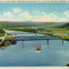
The backdrop will portray the landscape behind the railroad bridge.  The postcard below has the proper point of view (it looks north), but does not have the correct angle or distance to the bridge (it will be much closer).  Also, the Ft. Steuben bridge will not be depicted.  However, the general lay of the land, the river banks, mountains, and trees will be shown.


panhand


Lacking the skills to do something like this myself, I have enlisted the help of a friend who is an artist.  We had a discussion today and came up with a plan for treating the back wall of the layout.


More when I know it.


George

Attachments

Images (3)
  • v226 PRR Panhandle Track Plan - Annotated3
  • DSCN0458
  • panhand

Updated 10/18/2014:


I have to say that this Fall's York train meet was my best ever!  I finally took delivery of the 7' long, double track PRR Panhandle bridge.  East Coast Enterprises built it for me and it is a beauty (photos to come later)! 


My work on the foam "positive" of the bridge pier has not gone well.  I am unhappy with how it looks and have decided to pursue creation of a 3D model using SketchUp.  If that turns out OK, I will either have the piers 3D printed or use one model to cast two piers.


Prior to York, I managed to pickup some 4' x 8' sheets of 1/8" thick masonite.  I am going to start work on framing the backdrop.  As soon as it is done, I will apply Gesso and then call my artist friend to start painting.


George

Updated 10/31/2014:


With a memorable October now in the rear view mirror, I have turned my attention to the issues affecting the installation of the bridge.

  1. Backdrop:  As mentioned previously, I acquired 3 sheets of masonite measuring 1/8" thick by 4' wide by 8' long.  Each of these has received 2 coats of Kilz.  They are currently sitting in the garage awaiting a coat of Gesso.  That may happen very soon.  Then they will be sent to the artist.
  2. Bridge Piers:  This is turning out to be a real thorn in my side.  I have been experiencing problems making SketchUp portray the pier components properly.  While consulting with several SketchUp experts, I am also looking into alternative ways of constructing a "positive" in order to make a mold.  It's been two steps forward followed by 1 step back.

I am expecting to complete Item 1 shortly and have a solution for Item 2 from a vendor.  If that happens, I will look at fixing a long neglected electrical switch control problem and then chase bridge pier / river bottom installation issues.


And then we will be ready to install the bridge and run trains across it!  


George


Last edited by G3750

Updated 11/4/2014:

Just for your information, I thought I would relay some of the options I have pursued for the bridge piers:

  1. Have made my own SketchUp 2014 drawing. I am stuck trying to get the major portion of the pier drawing to taper correctly. No progress. I have contacted an expert (book author) for assistance in correcting the diagram. He is looking at it and will get back to me.
  2. I have attempted to hire a SketchUp designer to fix the diagram and to have the bridge piers 3D printed. This is extraordinarily cost prohibitive. "Shocked" is the best way to express the cost!    Maybe "horrified" or "obscene" will work as well. 
  3. I approached two specialty lumberyards about CNC milling of the bridge piers. Neither was interested.
  4. I have a tentative agreement with a local machine shop to make the piers out of wood. The price is pretty reasonable as well. I am cautiously optimistic that this will turn out well, but the jury is still out.

I had a sneaking suspicion that the bridge piers might be as troublesome to procure as the bridge. That suspicion seems to be coming true.  I still have an option or two up my sleeve if none of the above work out.

More when I know it.

George

Updated 11/6/2014:


I'm pleased to report that some progress is taking place on the backdrop front.  The photo shows the test fitting of the backdrop that will go directly behind the bridge.  There is still some cutting and fitting that has to take place.


Backdrop_02_

The areas where the bridge will be mounted (each end) had some extra supports left over from the old metal bridge.  I removed those.  These two spots will need some reinforcement and clean-up in order to be ready for the new bridge.


Backdrop_03_


I also got some good news on the bridge piers.  The person with the machine shop is going to start work soon.  Hopefully we will see these before too long.


More when I know it.


George

Attachments

Images (2)
  • Backdrop_02_
  • Backdrop_03_

Updated 11/15/2014:


There is a bit of progress to report:


  • Yesterday I attended the O Scale Train Meet in Strasburg, PA.  While this is primarily a 2-rail scale meet, you tend to see a lot of detail parts and kits that are absent from 3-rail meets.  I picked up some detail parts for building interiors.
  • On the way home back from the meet, I stopped at Cool Trains in Salunga, PA (really a terrific store with helpful and knowledgeable staff) and picked up my Plastruct order.  I received some parts for the bridge piers.
  • Also got some good news from the maker of the bridge piers.  The prototype is complete.  I'll be taking a look (in person) today.  Meanwhile, here's a photo.


IMG_0925


More when I know it.


George

Attachments

Images (1)
  • IMG_0925

Updated 11/23/2014:


I roughed out a floor for the top of the bridge pier out of .125 Plastruct.  I decided to play with the red, blinking LED and did a test installation.  Below are a few stills.  I might raise the floor a bit, it looks low.  Likewise, I think the bridge pedestals are going to get some minor elevation as well. I want them to look right.  Alternatively, I may be searching for some G scale bridge feet.


Lit_Bridge_Piers_06_

Lit_Bridge_Piers_07_


Ok, and here's some footage of the blinking LED.


Lots of adjustments still to be made.


George

Attachments

Images (2)
  • Lit_Bridge_Piers_06_
  • Lit_Bridge_Piers_07_
Videos (1)
DSCN0531
Originally Posted by G3750:
Originally Posted by Putnam Division:

That is one handsome bridge!


Peter

It certainly is.  At last Fall's York I had a serious discussion with the guys at East Coast Enterprises and they were very intrigued by the prototype.  I happen to think the prototype is one of the most beautiful railroad bridges in America.


IMG24


I think they captured the essence of the prototype in their model.  The real bridge, including approaches, is over 1,900 feet long.  Obviously you cannot reproduce the prototype as a scale model in 1:48.  That would be a bridge nearly 40' long, but the proportions are correct.


George

it is a handsome bridge, I see it everyday going to work at Half Moon.

Originally Posted by 69nickeycamaro:

George take the layout down you don't need it with that bridge. that is 1 fantastic piece of art its the best model bridge i have seen to date. in fact i'd be happy to "store" it on my layout.

Gee, I appreciate the offer, but I'm good.


Thank you, I think the bridge is pretty special, too.  The photos are kind of dark and don't do it justice.  I can't wait to get it on the layout, but the backdrop has to get painted first.  I also need to find the right set of bridge shoes (feet).  That snipe hunt is in progress.


George

Updated 12/13/2014:

Despite the sad events of the past two weeks, some incremental progress has occurred:

  • My supplier has completed the second bridge pier. I have not seen it, but expect it will be delivered shortly.
  • I have searched for commercially available bridge shoes of an appropriate size for the bridge and come up empty. Nothing big enough appears to be available (sigh).
  • I have taken a first cut at designing a properly sized bridge shoe. It's rough and after a review, I have some modifications to make. The goal is to end up with a series of Visio drawings of the components (triangles, rectangles). Those drawings will be used to make precision quantity cuts of parts (I'll need 8 bridge shoes). I will then assemble them.
  • Just below the bridge shoe is a (I'll call it a footer for lack of a better term) footer consisting of 8 "I" beams on edge holding up a plate. The bridge shoe rests on the plate. I've designed that and will start building those as soon as I have the materials.


That's all I know at the moment.

George

Bridge shoes seem like the perfect 3-D printer project. You may need help getting the drawings done....a few folks here on OGR might help, and then you could load them to the website 'Shapeways' where you or any modeler could order them. And parts that small and simple would be pretty reasonable.  Then anytime you needed more you can just order them. If I had mastered 3-D art software I'd do them for you....but I am stuck at 2-D for now. 

Originally Posted by AMCDave:

Bridge shoes seem like the perfect 3-D printer project. You may need help getting the drawings done....a few folks here on OGR might help, and then you could load them to the website 'Shapeways' where you or any modeler could order them. And parts that small and simple would be pretty reasonable.  Then anytime you needed more you can just order them. If I had mastered 3-D art software I'd do them for you....but I am stuck at 2-D for now. 

Dave,


They do seem like a good candidate for 3-D printing, but the attempt with the bridge piers left a bad taste in my mouth.  I have downloaded SketchUp 2014 and played with it.  I'm not great with 3D, but passable I suppose.  Certainly for something like this SketchUp would allow me to render it.  I didn't get the kind of SketchUp technical help I expected (even when I paid for it).  And the pricing for the piers was astronomically high - more expensive than the bridge!  Pricing for 3D printing of bridge shoes should be reasonable, but once bitten, twice shy.  I'm just not sure...


The guy who made my bridge piers is reliable and does spectacular work (as you can see in the photos).  My skills with a 2D drawing tool like Visio are pretty good.  That will probably be my first path.  If it doesn't work out, I have the 3-D printing option in my hip pocket.


Thanks,


George

I understand.....I made an attempt at learning 3-D software. I have a laser cutter and claim to be pretty good at producing art for my laser.....so 3-D was the next step. TOO frustrating for me to tackle right now.

Maybe cut them on a laser and assemble them?? Cut from plastic sheet stock would be a little more work....but not hard. Good luck!

Updated 1/9/2015:


  • I completed the design (about the 4th revision) of the bridge shoes.  Also found a supplier for the ABS sheets that will be needed.  All these parts will be cut by CNC machine as they need to be precise and in quantity.  I will end up doing the assembly.
  • Now that the design is done, I was able to compute the height of the backdrop from the riverbed to the bridge deck.  I will move the module floor (riverbed) to the proper height.  The piers (with their shoes) will snug up against the bottom of the bridge deck; I want to make sure that all 8 bridge shoes are bearing the weight evenly.
  • The backdrop will also be notched correctly to fit into the module.  The artist and I will then draw the major landscape components onto the masonite and she can get painting.


More when I know it.


George


Updated 1/20/2015:

  • My cataract surgery (right eye) went well yesterday. I can see out of my right eye again!!!!! Woo Hoo!!! I will need glasses for close up work and reading, but wow are the colors popping! Lots more light in my life right now.
  • Did some work on the DZ-2001 Data Wire Driver (Switch Bus) issue today. I have come to understand that the total buss length shouldn't exceed 75 feet in length. Mine, as it stands today, is longer than that.  And as I have reported in the past, I have experienced loss of signal on the hidden storage yard switches (switches #17, 18, 19, 20, and 21). The answer is to split the long bus into two busses.  I am in the process of putting Switch Bus #1 together.  I have hopes of putting this together sometime later this week. This work needs to happen before the scenery backdrop behind the PRR bridge goes into place.
  • In support of the work above, I have some additional 4 conductor wire on order - due Friday.


Feels great to be able to see and good to be getting something real done on the layout!!!!  


George

Originally Posted by rtr12:

Good to hear your cataract surgery went well. I can a=imagine what a difference that would make. Good to hear your vision is so much better as well. I have same problem also in right eye. Hoping it will be ready for surgery this spring. How long did you have to wait before they would repair yours?

Well, I had gotten a new eyeglass prescription in February 2014.  (I've been under treatment for glaucoma and cataracts since 2008).  I started noticing blurriness and a lot more glare at night in mid-summer.  I had my eyes rechecked and it had significantly changed.  That and the pressure in my eyes increased.  At that point, my optometrist told me my eye was getting visibly worse.  He wrote an opinion to my eye specialist and we scheduled the surgery. 


I would recommend that you stay on top of your doctors about your readiness.  I intend to do the same to get the left eye done.


George

Updated 1/22/2015:


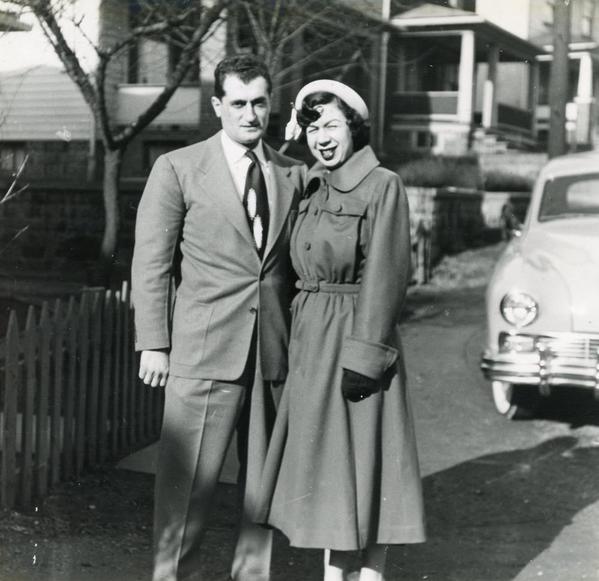
This photo surfaced last month when the slideshows for my parents' funerals were being assembled.  My brother-in-law scanned in a bunch of shots and preserved them.  It's a nice photo of my parents that dates from the early 1950s (just after their marriage) or the late 1940s (when they were dating).  I have decided to look for similar figures (Artistta or others makers) and put them on the layout as a mini-tribute to them.  From a purely aesthetic point of view, I think it's a neat 1950's photograph (especially with the background and car).


JGP082


I recognize the area, too.  The photo was taken on Terrace Circle in Weirton in front of my maternal grandparents' house.  In 1967, that entire street was purchased by Weirton Steel for use in their Basic Oxygen Plant (BOP) referred to as the Mill of the Future. 


Anyway, I think two figures like these need to be on the layout somewhere.


George

Attachments

Images (1)
  • JGP082
Last edited by G3750

Updated 1/24/2015:


  • Work on Switch Bus #1 is proceeding.  I've cleaned up the spot on the western distribution panel where the DZ-2001 wires split into two busses.  That is now a terminal block.  Switch Bus #1 is now a closed loop.  I've tested the 3 installed switch machines - No. 1, 2, and 3.  They work fine.  I still have to hook up the switches in the hidden storage yard - 17, 18, 19, 20, 21.
  • Picked up my 4 conductor wire Friday.  I have started removing the old buss conduit from under the passing siding.  I hope to replace it with the new stuff soon.
  • If I were to do this over again (and that is the plan when we retire), the distribution panel will get re-worked.  Right now it is not as clean and organized as I would like, but that is a result of all the changes that were made.  The same piece of wood first hosted a DCS set of components, then both DCS and TMCC, and then was reworked as several other TMCC components were added and power supplies changes.  [Lesson Learned]

Feels good to be doing some wiring work again.


George


Updated 1/25/2015:


I got tired of watching the NHL All Star Game and decided to do some work on the layout.  Switch Bus #1 has been relocated.  I moved the wiring connections (AC Hot, Common, Data Wire) for Switches 17 & 18 to new locations on Switch Bus #1.  I'm happy to report that these two switches are working!  They are functioning via push button and CAB-1 remote.  All 5 switches 17-21 are located in the Hidden Storage Yard, so I am spending time under the layout working with extra lighting.


Here's what the yard looks like.


Storage Yard-Annotated


Switches are all Ross and are equipped with Z-Stuff DZ-2500c switch machines.  They have been programmed and tested for awhile now.  I'm just getting around to installing them.  No. 19 will be the next one.


George

Attachments

Images (1)
  • Storage Yard-Annotated

Updated 1/28/2015:


After much grief, crossed-eyes, and cramped sitting and working under the layout, I am pleased to report that all 5 switches in the Hidden Storage Yard are functioning under both CAB-1 and push-button control!!!


Now, let me get the lessons I learned down while the pain is still with me:

  1. Minimum layout height should be 36" (mine is 27" - ouch).
  2. Never, ever, ever, ever (did I say never?) install switches on a layout without testing their operations first.
  3. More labels on wiring!!!

OK, I feel better now!


George


Last edited by G3750

Updated 1/31/2015:


Here are some photos of the updated wiring for Switch Bus #1.  First photo shows the point where the loop terminates (just west of the bridge).  The 3 sets of suitcase connectors (left to right) supply TMCC signal (white), AC Hot (red), and Common (black) to switches 19, 18, and 17, respectively.  The white wire running across the photo at the bottom of the 1"x4" is the ground plane for the hidden storage yard, which is visible only as the edge of a piece of plywood.


DSCN0645


Photo 2 shows the termination of Switch Bus #1 at the Western Distribution Panel.  Both ends connect to a 6 position barrier strip.  Wires proceed downward from that to the DZ-2001 Data Wire Driver board (connected to the bottom of the Command Base at the right).  As indicated by the label, power supplied to the bus is 15 VAC.  Switch Bus #2 will eventually connect to this same 6 position barrier strip.


DSCN0650


George

Attachments

Images (2)
  • DSCN0645
  • DSCN0650
Originally Posted by rtr12:

I like the little tags you have that can be tied to the wires. All I have now is a Brother labeler and the tags don't stay on the wires very well as they are. I need to do something different. Where did you get the ones you are using? I think I might like to try them.   

Waytek (www.waytekwire.com) sells various sized tags.  I used product #52302 that takes a 2" label.  I think they have a number of various sizes.  There are also cable ties that come with a small flat area for labeling.  On these, I've used Avery labels, but they tend to fall off after awhile.  I am currently using a Brother P-Touch labeler (PT-1880).


Please let me know what you end up trying.


George

I can tell you a little about a few different labels that I used in my working life before retirement.


Brady markers, numbered and lettered, they come in a booklet. Available in different configurations of numbers and letters. Ok, but limited for descriptions and sometimes come loose over time.


Brady labels (there are other brands as well) that come in a booklet that you can write on. These stick pretty well when new and you can write what you want on them with a pen or fine point Sharpie. Not too bad. You can also get these (or similar from other brands) in various sizes an 8-1/2"x11" sheet for printing from a computer. Special software required and I don't now what that costs (probably expansive)? 


Brady label machine (similar to Brother or Dymo) that makes tags especially for wires. These are pretty nice. The labeler is expensive and so are the labels. They use a label cartridge like the Brother machines, also expensive. Cloth labels work very well and are also the most expensive. The printing can also be pretty small (maybe too small for my old tired eyes).


Engraved nameplates (very similar to the ones you are using only machine engraved and very $$$) with the 2 holes in each end for tying to wires. They required different colors for the type of device the wire was serving. These were just like yours (only thicker and engraved) and they were also the same size as yours. 


The ones you have found look to be cost effective, large enough for a fair sized label and probably an excellent choice. I would imagine these could also be used with just a Sharpie? I think I will try ordering some and try them out.


I imagine you have seen the labels a part of the ty-rap at the link you provided, but the labels were a lot smaller and they were a bit more costly. Probably not as good a choice as the ones you are using.

George,

The wiring and labeling is excellent!  I agree with you, rtr12, and Dale that labeling is essential.  I have worked in electronics as a technician and now engineer for over 38 years.  I have seen good labeling and poor labeling.  On a year long project a couple of years ago for the telecommunications company I work for, I emphasized the need for labeling to the folks in another state who were running the project, but didn't think it was important.  They can go on their merry way as far as I'm concerned, but when they told me we were wasting time documenting and labeling where every fiber patch cord went and what circuit it was, I told them we would continue 'wasting our time' as we have in the past.  

Guys,


Yes, a Sharpie works just great on these tags.  I've done that, too.


I have used Word to print Avery labels.  The majority of the labels on my layout are Avery printed with Word.  Unfortunately, they have started to fall off.  Very annoying after all the trouble I've gone through to make them.


Mark - the small effort made to correctly label, organize, and record connections pays off big time when you're hunting a fault.  I've seen that in my layout and in the real world.


George

Avery has both removable and permanent labels. The permanent may stay on better? I don't know if they have all sizes in both kinds however? I hadn't thought of Word. I have it, an older copy, but seldom use it. I think they used that in our office (when I was working) to do Avery labels. Come to think of it, I believe they used Word to print the 8-1/2"x11" wire label sheets I mentioned above as well, so I was wrong about the special software (unless you don't have Word). How quickly we forget?


I believe in labels too! Putting them on at the time of pulling/installing the wire is also a must if you have multiple wires, unless you have lots and lots of colors or want to spend a long time ringing them out. Might as well use good ones with meaningful descriptions on them.


As for wasting time with labels, that sounds like some of the managers we used to get that were trying to make a big quick bonus for cutting costs and increasing profits. They were usually let go a year or two later and we were stuck with the messes they left behind. And that was a BIG company. I finally left after 20 years, because of stuff like that. Spent my last few years working for one of my co-workers from there that left there before I did for the same reasons. He bought a small competing company, I went there. He is still doing very well and still labeling all the wires, very nicely I might add.

If you can color-code rather than write out a full label, various colors of Duct Tape will work. You can also tag everything on one circuit with the same color, then write on each tag with a Sharpie, renewed as necessary.


Bright-colored nail polish will work on some things and is more durable than most labels, but I'm hesitant to put it on wiring because of the solvents in it.

Originally Posted by rtr12:

Avery has both removable and permanent labels. The permanent may stay on better? I don't know if they have all sizes in both kinds however? I hadn't thought of Word. I have it, an older copy, but seldom use it. I think they used that in our office (when I was working) to do Avery labels. Come to think of it, I believe they used Word to print the 8-1/2"x11" wire label sheets I mentioned above as well, so I was wrong about the special software (unless you don't have Word). How quickly we forget?


I believe in labels too! Putting them on at the time of pulling/installing the wire is also a must if you have multiple wires, unless you have lots and lots of colors or want to spend a long time ringing them out. Might as well use good ones with meaningful descriptions on them.


As for wasting time with labels, that sounds like some of the managers we used to get that were trying to make a big quick bonus for cutting costs and increasing profits. They were usually let go a year or two later and we were stuck with the messes they left behind. And that was a BIG company. I finally left after 20 years, because of stuff like that. Spent my last few years working for one of my co-workers from there that left there before I did for the same reasons. He bought a small competing company, I went there. He is still doing very well and still labeling all the wires, very nicely I might add.

Is there any special designation for the permanent types of Avery labels?  Where would I find them?


Thanks,


George

I have seen them at the large office supply stores like Office Depot. If I remember correctly, the removable ones were specifically marked as removable and the permanent were not marked. They didn't have every size in both types. As I recall only a few were removable. File folder labels are one type where I think had both? It could also be that the permanent ones just don't stick well to the plastic tags? Avery website might have more details?  

Originally Posted by G3750:
Originally Posted by rtr12:

Avery has both removable and permanent labels. The permanent may stay on better? I don't know if they have all sizes in both kinds however? I hadn't thought of Word. I have it, an older copy, but seldom use it. I think they used that in our office (when I was working) to do Avery labels. Come to think of it, I believe they used Word to print the 8-1/2"x11" wire label sheets I mentioned above as well, so I was wrong about the special software (unless you don't have Word). How quickly we forget?


I believe in labels too! Putting them on at the time of pulling/installing the wire is also a must if you have multiple wires, unless you have lots and lots of colors or want to spend a long time ringing them out. Might as well use good ones with meaningful descriptions on them.


As for wasting time with labels, that sounds like some of the managers we used to get that were trying to make a big quick bonus for cutting costs and increasing profits. They were usually let go a year or two later and we were stuck with the messes they left behind. And that was a BIG company. I finally left after 20 years, because of stuff like that. Spent my last few years working for one of my co-workers from there that left there before I did for the same reasons. He bought a small competing company, I went there. He is still doing very well and still labeling all the wires, very nicely I might add.

Is there any special designation for the permanent types of Avery labels?  Where would I find them?


Thanks,


George

OK, I just answered my own question!   The labels that go with the Waytek 52302 ID plates are the Avery # 05430.  I found the package and they are the removable kind.  Sheesh!


And now I understand why I'm having problems.


I have just visited the Avery website.  Let's just say that it's less than swift.  I had to call them and speak with customer service.  I spent 15 minutes on the phone with them before they were able to tell me that they do not have a permanent label that fits those ID plates!


Back to the drawing board, I guess.  My choices are:

  1. Glue my labels to the ID plates (cheapest solution, maybe)
  2. Find permanent labels and new ID plates (major PITA and additional expense)!


George


This might be a PITA too, especially if you use a printer, but maybe get larger ones and cut them down? Would work for hand written tags. You might have a hard time finding any other ID plates like you have already found. I think those are pretty nice and don't recall seeing anything similar before seeing yours. Maybe a glue stick would work to hold them on better? Very easy to use, but don't know how they work on plastic?


I actually thought Avery had just about everything in permanent and very few in removable, shows what I know about them as well, not much I guess? Sure seems like the removable were hard to find when I was wanting some a while back when we moved.

Originally Posted by rtr12:


I actually thought Avery had just about everything in permanent and very few in removable, shows what I know about them as well, not much I guess? Sure seems like the removable were hard to find when I was wanting some a while back when we moved.


That's what I thought, too.  It was only when I finally found the package that I realized the labels were removable.


I'm going to try something called Glue Dots.  If that doesn't work, then maybe Aileens Tacky glue.  Failing that I will tape the labels back onto the plastic.  With over 100 labels, this is going to be a total PITA.


George

Updated 2/2/2015:


You know?  Maybe I am experiencing Ground Hog Day all over again! 


I could swear I had done all this wiring logically before.  Anyway, I have (apparently) opened Pandora's Box by trying to simplify the wiring.  Here is what's going on:

  • For Power District 2 (the bridge), I have removed 5 of 9 track feeder pairs.  I will need to check these.
  • Because the labels have fallen off most of the remaining track feeder pairs, I will have to re-do them.  That's not going to be fun.
  • I've yanked a bunch of wiring out from under the Hidden Passing Siding and off the Eastern Power Distribution Panel.

Here's photo of the wiring changes in mid-stride.


DSCN0670


The Eastern Panel is a lot less cluttered right now.


DSCN0668

Lots more work to do.


George

Attachments

Images (2)
  • DSCN0670
  • DSCN0668

Updated 2/15/2015:


I don't have any photos, but a fair amount of work got done today.

  • All 7 feeder pairs for Block 8 (Weirton Steel Yard) were identified and re-labeled.
  • All 2 feeder pairs for Block 3 (Weirton) were identified and re-labeled.
  • Accessory bus wires for switches 8, 9, 10, 11, 12, 13, 14, and 15 were labeled.
  • Brackets were installed on the east edge of the layout to hold a masonite backdrop
  • General wiring clean-up took place - more cable ties were added.

I didn't get as much as I wanted done, but real progress was made.  The work isn't particularly photogenic.  It would hard to tell progress from the photos in the previous post, but it did.  I am on the verge of connecting the ends of Switch Bus #1 together.


George

I didn't get as much as I wanted done

George, that's the story of my own layout work in a nutshell.  As long as SOME progress was made, chalk up a win.  Wiring is definitely my own least favorite thing to do because it does take so much time and yet is invisible to anyone viewing the railroad.  You're doing a great job, just keep plugging along.

Originally Posted by Bob:

I didn't get as much as I wanted done

George, that's the story of my own layout work in a nutshell.  As long as SOME progress was made, chalk up a win.  Wiring is definitely my own least favorite thing to do because it does take so much time and yet is invisible to anyone viewing the railroad.  You're doing a great job, just keep plugging along.

Thanks Bob!  It's funny, but I really thought things were in better shape under the layout than they actually are.  I'm doing way too much wiring rehabilitation


I'm building a big list of lessons learned for the (God willing) next incarnation of the Panhandle.


George

Updated 2/17/2015:

I finished wiring up Switch Bus #2 (or so I thought) last night and tried it out. Nothing except some chattering and alternate light flashing from some DZ-2500 switch machines. Not quite sure what's going on. I disconnected Switch Bus #2 and tried again - Switch Bus #1 works perfectly. Disconnected Switch Bus #1 and connected #2 and tried again. This is even more strange - only a couple of pushbuttons are powered. Clearly something is mis-wired. I will have to examine this in the light of day and when I have a clear head.

George

Updated 2/26/2015:


I have a few things to report.

First, some progress has been made with Switch Bus #2. A bad crimp was isolated and power is now flowing to all DZ-2500a switch machines on Bus #2. We still don't have a functioning DZ-2001 signal to each, but we are making progress.  More debugging is planned.

Second, the bridge shoe components arrived yesterday. I am in the process of doing a test assembly. So far, things look really good. The parts are going to get painted a flat black tomorrow at my friend's paint booth. When I have one fully assembled, I'll post a photo.

I found the appropriate color for the yellowed concrete of the PRR bridge piers. The piers are going to get painted tomorrow as well. Then I plan to weather them with powder and apply Dullcote.


More when I know it.


George

Updated 3/25/2015:


  • Still debugging my Switch Bus.  Progress here is slow, but all switches except 1 are operating correctly via push-button.


  • Finished making and painting the floor for the top of each bridge pier. 


  • Painted both bridge piers using a color called Satin Strawflower.  The concrete on the prototype is old and has yellowed significantly.  As goofy as you might think it is, the color does closely approximate the real thing.  Here's a photo of the piers with my bridge shoes (test fit only).


DSCN0723

Still need to install the pedestals for the bridge shoes, red blinking warning lights, and railings.  But we're getting there!


George

Attachments

Images (1)
  • DSCN0723

Updated 3/29/2015:


I spent some time over the weekend trying to debug my Switch Bus issues without too much forward progress.  I probably have more than 1 switch machine malfunctioning.  To isolate the problem and to simplify things a bit, I decided to run each Switch Bus from its own DZ-2001. 


Yesterday, I made the wiring changes at the Western Distribution Panel.  Switch Bus #1 now works perfectly.  Its switches operate correctly from either their push buttons or the CAB-1.   Pretty happy about that; no more connecting / disconnecting bus wires when debugging.


Perhaps today, but certainly over the rest of the week I will focus on isolating the malfunctioning switch machines on Switch Bus #2.  We already know #14 is bad.  We suspect #9 is also problematic.  Interesting coincidence? that both machines are the first ones in cross-over pairs (9 & 10, 14 & 15)?  Hmm.


Anyway, I have gotten another lesson learned out of this.


Initially, the Western Distribution Panel was designed for DCS (TIU, AIU) and TMCC (Command Base).  There was enough room for these components back then.  When I changed to TMCC only, some space was freed up, but then quickly consumed by the larger number of ala carte TMCC components (TPC, BPC, AMC, ARC) and associated wiring paths. 


The Lesson:  make your panel as big as you think you will ever need, then double it!  From observing some of the panels in the toll industry, I've come to realize that laying them out efficiently and logically is an art.  Most of us experience the creeping incrementalism and direction changes that result in somewhat cluttered panels.  Anyway, I've got another lesson for the next incarnation of the PRR Panhandle.


George

Last edited by G3750

Updated 4/19/2015:

  • Attended the Strasburg O-Scale Show on Saturday. This is a terrific show.
  • Last week I started to cut lumber for additional ribs for the river bottom module. This module will hold the river bottom, the bridge piers, and the end piers and hillsides for the bridge. At the very rear, it will support the backdrop. Murphy's Law raised its ugly head: the miter saw blade needed to be replaced.
  • On Saturday, I found an inexpensive, better replacement (180 tooth / $12) at Lowe's.
  • On Sunday, I cut both additional ribs and started screwing them into place. The existing ribs will be moved about 0.75" to help support the bridge piers. I drilled holes for wiring in all the ribs.
  • Got my shopping list ready for York. Will attend a bandit meet for the first time on Tuesday.


George

Originally Posted by Pingman:

I continue to follow your progress and appreciate the updates.


Suggestion:  edit the thread's title with the date of the update; makes following the thread that much easier.


Thanks, again, for taking the time to allow us to follow along.

You're welcome, Carl.  I wish there was more progress to report, but I had the remaining eye operated on 2 weeks ago (cataract surgery).  It went great and I now have 20/20 in each eye and only need reading glasses!     I feel like a 20 year old again!!!  Between that, Orthodox Easter, and work, I haven't had much chance to work on the layout.  Hopefully that will change after York this week.


George

Last edited by G3750

Updated 4/26/2015:


As noted elsewhere, I had a pretty stellar York (although not quite as awesome as Fall 2014):


  • K-Line 18" PRR Spirit of St. Louis 4-car passenger set
  • Williams PRR B6sb (about to get TMCC / Sound / and F/R electrocouplers)
  • 2 Weaver PRR B60b baggage cars
  • 1 MTH R50b refer express car
  • 2 MTH N6b cabin cars
  • 1 Weaver TTX/REA TTOFC
  • 1 MTH Hot Metal Car
  • Some figures, detail parts, misc. pieces

If the Fall 2014 York was a grand slam for me (the PRR Panhandle bridge), this one was a 3-run homer.


George

Updated 5/6/2015:


Finally managed to get some work done on the layout:

  • Moved the original cross-members in the river bottom benchwork module.
  • Installed extra cross-members in the river bottom.
  • Procured regulated 12VDC and 5VDC power supplies to replace the unregulated power supplies procured from old computers.
  • Ordered 100' of Yellow/Black 16 gauge 2-conductor zip cord for use with the 12VDC power supply.
  • Ordered 100' of Red/Black 16 gauge 2-conductor zip cord for use with the 5VDC power supply.
  • Wrapped and suspended the wire bundle that goes behind the central backdrop (under the Hidden Passing Siding).

George


Last edited by G3750

Updated 5/8/2015:


Here are some photos to accompany the previous update.


First, the river bottom module and its new cross-members.


Wiring_21_

Wiring_20_

Next, the regulated power supplies.  5VDC on the left; 12VDC on the right.  Note that you can buy these new for very little coin.  They are much safer than using unregulated computer power supplies.


Wiring_25_

Wrapped and suspended the wiring bundle under the Hidden Passing Siding.  This looks a lot better to me now.


Wiring_24_

Wiring_23_

Wiring_22_

OK, now we need to make sure that the river bed module is actually level and properly positioned / attached to its legs (see Photo 1 for reference).  In order to have the backdrop and bridge piers fit correctly, we will need to have the module level left to right and front to back.  That's the logical next step.


George

Attachments

Images (6)
  • Wiring_21_
  • Wiring_20_
  • Wiring_25_
  • Wiring_24_
  • Wiring_23_
  • Wiring_22_
Last edited by G3750
Originally Posted by Mark Boyce:

George,

An absolutely first rate job.  Cable harness looks neat and tagged, the regulators look good, and the bench work for the river bed looks good, and you still plan to level and test fit.  If I was hiring someone to do my work for me, and you were in the business of building others' layouts, I would give you the job!  ;-)

You're too kind, Mark.  Unfortunately, all of this is remedial work.  I did the initial (bad) job hurriedly.  The good news is that I learn from my mistakes.  The bad news is that I have way too many opportunities for education. 


But thank you.


George

Add Reply

Post

OGR Publishing, Inc., 1310 Eastside Centre Ct, Suite 6, Mountain Home, AR 72653
800-980-OGRR (6477)
www.ogaugerr.com

×
×
×
×
Link copied to your clipboard.
×
×