
After Christmas I bought this string of LED lights on clearance thinking I may be able to replace the lights in my MTH RK streamliners to cut down on heat and amps.

IMG_2129

Well of course the GE base is unlike any other and wouldn't fit the MTH socket.  Since I had the car apart, I removed one of the LEDs from it's base and inserted it into a MTH base.  I decided to test it before installing it.  Thinking LED=DC I broke out a HO transformer gave the new bulb a little juice.  Bright flash and the bulb was done.  Idiot, the string is meant for AC that's why I bought it.  Tried again with a new LED and a Z750 transformer.  Same result.  Neither time did I apply much current.  So now I'm confused.  Was my basic premise about using these LED bulbs to replace the incandescent ones flawed or did I do something wrong.  The plug on the string of lights looks like a normal Christmas light plug not a transformer or anything unusual so I thought the conversion from AC to DC happened in the bulb.  Am I missing something?

Attachments

Images (1)
  • IMG_2129
Original Post

Replies sorted oldest to newest

@coach joe posted:

Neither time did I apply much current.  No, the dial on your transformer controls VOLTAGE NOT CURRENT.

So now I'm confused.

Was my basic premise about using these LED bulbs to replace the incandescent ones flawed or did I do something wrong. The LED in an of itself is, fine- no different than any other LED- where you failed- it's right in the name, an LED is a diode- a special one, but a diode. When it conducts it's like a diode and thus needs current limiting or else they burn out in short order. Go ahead- put a diode directly across your transformer- it will react the same way- conduct massive current until it too burns up.

Am I missing something? Yes, as pointed out, you need a resistor in series with the LED- and possibly a blocking diode to prevent the reverse voltage from AC also causing a failure.

Again, let's do the 101 on electricity here:

Voltage is like water pressure

Current (Amps) is the VOLUME of water flowing- an 8 Inch pipe diameter vs 1/2 Inch pipe diameter.

A diode is like a one way check valve. In the same analogy- that check valve has a pressure limit that is different in both directions AND also has a flow limit.

An incandescent bulb has a special characteristic. The tiny wire filament has resistance. The key is, that resistance changes with temperature. So when it heats up, it gets more resistive and less current. Less current is less heat, so the filament heats up, then reaches a self regulating high temperature. It controls the current.

An LED (Light Emitting Diode) is a diode (one way check valve) One way, no current flows through it, the other polarity current flows through it above the threshold "turn on" voltage -AKA "forward voltage" of the diode and once it begins conducting, it's like an check valve that pops fully open allowing near unlimited current. So with an LED- you need another device in the path to limit current- a resistor.

And... an LED like I said has several ratings or limits and one of them is peak reverse voltage. Again, think of a check valve, how much back pressure can the valve take in reverse (the closed state) before it just blows through and breaks the valve? This is why adding a higher rated peak inverse voltage diode in series- protects the sensitive and special LED diode from repetitive peak inverse voltage from an AC power source.

Again, you took a bare LED, no protection of any kind- no current limit and no reverse voltage protection- connected to power sources capable of Amps of current and the LED blew in a flash.

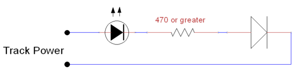
Excellent example and diagrams of doing it right

https://ogrforum.ogaugerr.com/...1#159660139239386791

Not rocket science here, for an LED from track power, complete with reverse voltage protection for long life, here it is.  The resistor value of 470 will give you an average current of close to 20ma with 18 VAC track power, I typically use a 1K resistor to cut that to half as the LED's are more than bright enough with half the current.

Here's my illuminated yard switches, these LED's each have a 1K resistor and all of the LED's have a single diode to the track common for reverse voltage protection.

You can add as many LED resistor pairs to a single protection diode as you need, especially if they're in one place.  Just keep stacking them up.

Without trying to derail this thread, I have a question about some 3V LED's that I am powering with a 9V battery. The LED's came with resistors to limit the current. Can I connect three of these LED's in parallel to a single resistor before connecting the set to the 9V power source? Or must I pair each LED to one resistor?

This debate comes up often.

Remember- I explained an LED is a diode and once it conducts it has limited or minimal resistance.

The why that matters in the scenario you just presented. If you assume all the LEDs are identical and each one exactly has the same internal resistance and exact same forward voltage for turn on- then in parallel, the assumption is each gets is fair portion of the current.

What can happen in reality when LEDS are in parallel with a single source current limiting resistor- one of them turns on and conducts at a slightly lower voltage and thus conducts more current. This "steals" current from the other LEDs in parallel. They may not light or may be dimmer and this one super bright- until it burns out. Now you have the other 2 LEDs and the resistor is still allowing the SAME total current as before, but now we only have 2 LEDS so they get more than normal current- until one of them burns out- now the last LED gets slammed with 3 times it's original current and burns out.

Can you "get away with it"?? Yes, many folks do this and reasonable manufacturing tolerance on the same exact color and batch of LEDs is semi reasonable. The more LEDS you put in parallel- the greater the risk because the total current is now X times greater than any one single LED. So if one fails, then the rest begin to fail in very rapid order.

Again, 2 LEDs- OK fine and the current limiting resistor is probably sized so that the burned out LED scenario is not pushing the lone LED into also blowing.

3 or more in parallel? I cannot recommend a single source current limiting resistor. This is where you begin individual resistors.

Just my opinion and experience. Your layout, your trains, your rules.

Last edited by Vernon Barry

Edit to the above:

some 3V LED's that I am powering with a 9V battery. The LED's came with resistors to limit the current. Can I connect three of these LED's in parallel to a single resistor before connecting the set to the 9V power source? Or must I pair each LED to one resistor?

Just a tiny bit unclear to me the actual construction at hand. In other words, you said you have some 3V LEDs (well certain colors are 3-4v forward voltage) that came with resistors (a pack of resistors or resistors already soldered in series with the individual LED?) and then- adding another resistor in series to the 3 LEDs in parallel from the 9V source? I'm asking because you can and I have bought LEDs from suppliers pre soldered with wiring and an in series resistor all neatly packaged. They rate them for a certain voltage the the value of resistor was chosen to be correct for that LED and that voltage. I've also bought LEDs that came with a bag of resistors- and even resistor assortments- labeled with different voltage ranges.

Point being, there are all kinds of parallel and serial scenarios that could work, won't work, or might be the cascade failure mode I described earlier.

Sorry for the confusion. The lights came in one bag, and the resistors in another, all in the same package. So I connected three lights together in parallel, then connected one resistor between the red leads from the lights and the + terminal on the 9V battery, and the black leads from the lights to the - terminal. The lights came on just fine, but I worry whether using just one resistor is inviting trouble.  Rereading your two posts just now, I can see that it would be better to use one resistor for each light, to minimize the chances of a cascading blowout. Thanks.

Last edited by West Side Joe

I connected three lights together in parallel, then connected one resistor between the red leads from the lights and the + terminal on the 9V battery, and the black leads from the lights to the - terminal. The lights came on just fine, but I worry whether using just one resistor is inviting trouble.

Yes, and that is the cascade failure scenario.  It assumes the LEDs are perfectly matched. Again it works- all the way until it doesn't. It might work for a long time, it might fail the next time turned on.  The more LEDs in parallel, the greater the risk of cascade failure. 2- OK, not insane risk, 3, higher risk, 4 even higher risk, 10- definitely full pucker factor. Also- turn on in theory- each time- whatever one conducts first takes a hit and spike in current each time turned on.

@coach joe posted:

So my error was thinking these were LED "bulbs" such as the the ones Town and Country sells, with the resistors built in when these are just LEDs and whatever resistance is built into the wiring?

Correct, the wiring is what handles the voltage and current. Specifically they place the LEDs in string series- because this allows the adding up of the forward voltage to be near the line current DC rectified voltage- thus the current limiting resistor is more efficient because it's not as great a loss.

Keep in mind- they (these commercial light strings) are meant to be cheap to make. If each LED is custom and has resistors- then that's expensive. String a bunch in series, and less resistors- way, way, cheaper to make.

That's why custom LEDs with built in self regulating current are more expensive.

Last edited by Vernon Barry

Add Reply

Post

OGR Publishing, Inc., 1310 Eastside Centre Ct, Suite 6, Mountain Home, AR 72653
800-980-OGRR (6477)
www.ogaugerr.com

×
×
×
×
Link copied to your clipboard.
×
×