I can't find a condensed troubleshooting guide for TMCC/Railsounds on the web or in the forum or a parts breakdown for my engine and tender.  Is there one somewhere?


I have lost all sound on my steam Pennsy K4 #3678 bought new circa 2004 IIRC.  I started having problems three weeks ago after a minor derailment with track short that popped the quick acting breaker I have on the track.  It began as stuttering chuffs that over the course of a week dropped out to no chuffing, just random trackside sounds while it was running.  The whistle and bell, and other sounds still worked. I tried a factory reset - no effect.  I tried reseating the card inside the engine and that seemed to bring the chuffing back for awhile, but the problem quickly returned.  Over time I also lost the squeal from the brakes.  The other day I finally looked in the tender and discovered two boards there.  I removed and reseated both, since both seemed to be riding a little high on their pins.  I seated both fully down.  After powering up the track lights were dim and I smelled smoke coming from the forward board in the tender.  I quickly shut off the power, but now I have no sound at all.  The large capacitor on the right side of the tender and the shielded coil on the same side toward the front of the board felt warm.  I could not see any bulging of the capacitor - the usual sign that it's blown and I couldn't spot any burned areas on the board itself.  I removed and reseated both boards a little higher and retried, but no sound at all now.  Running it with the naked ZW without the radio control also has no sound.  This engine has been jinxed since purchase.  It stopped smoking after a similar minor derailment / track short shortly after purchase and that was repaired under warranty.  (Are these electronics that fragile that a simple short kills them?)  What do I do next?  I have no spare boards to substitute.

Original Post

Replies sorted oldest to newest

Message sent.  I may shoot some photos of the engine and tender with their shells off.  I'd like to know what each board is/does, and it can serve as a reference for others who look at this thread.  Identifying these boards and how to test them is something I couldn't find on line.  Just having a parts breakdown for my engine, something that wasn't in the instruction manual, would be a help.

I thought about having gotten it put on one set of pins over, but I don't think I did that.  I didn't lift either board very high off of its pins, and then just put it back down.  The one thing I did differently was that I seated both boards fully down so that the pins were not visible.  I don't know how that would have cause the problem, but that's the only change that I know of.

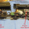
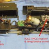
OK.  Here's an updated photo layout of the boards in the tender and engine for anyone who's troubleshooting.


Since the loss of sound, the rear coupler also no longer works.  When I push the uncouple button on my CAB-1 I can hear a sound at the coupler, but it doesn't open.  It doesn't seem to have the oomph it used to have.  Is that related to the audio power supply board? 


Before the complete loss of all audio, I thought it might be the green cherry switch in the engine that wasn't working.  Are there pins to check continuity of this switch?


01 Over view of engine and tender with shells off - proper board names - cropped [Large)

Attachments

Images (1)
  • 01 Over view of engine and tender with shells off - proper board names - cropped (Large)

For this engine the tether moves track power from the engine to the tender.  You also have serial data from the engine R2LC go to the tender and the signal for the rear coupler.  I would remove tender from engine, place engine on the track and reprogram it with the instructions.  This will reset the R2LC.  The engine can be tested by it self for motion, smoke and headlight control.


Check the rear PCB and make sure the solder joints are all good.  Then plug in the tender and check continuity through the harness.  If good move to placing tender on track by it self.  Do you get any sounds?


Because you had smoke I would remove the tender boards, and inspect the mother board for a burned trace.  If that looks good inspect both boards.  At this point you need to swap boards to test further.  Do you know where the smoke was coming from?  Might help with the selection of which board to swap first.  Any RS 4 boards can be used in the swap.  I would also check speaker for ohms.  Should read 8 or 16 ohms.   Probably marked on the top of speaker.  G

Last edited by GGG

Motion, smoke and front headlamp all work correctly.  It will take time to do the other tests.  The engine was reprogrammed with the tender connected before I took the Christmas trains apart, and the CAB-1 setup is packed up.  Would it do anything to reprogram the engine without the tender connected?


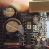
The smoke seemed to come from the vicinity of the two large capacitors on the audio power supply board in the tender, although I couldn't say it was a capacitor that smoked.  Neither capacitor looks bulged to my eye.  Those two capacitors and the shielded coil near them were warm when I touched the board to lift it off and reseat it, thinking that pressing it completely onto the pins had caused the short.  Although I didn't think that I moved over a row of pins when I seated it the first time, that is the most likely scenario since it smoked right after I put the board back on, yet I don't believe I had a row misplaced.  Photos of the offending board below.

14 Tender - top of audio power supply board [Large)

15 Bottom of audio power supply board - cropped [Large)

Attachments

Images (2)
  • 14 Tender - top of  audio power supply board (Large)
  • 15 Bottom of audio power supply board - cropped (Large)

If the Serial data was being effected by the damaged tender component it "might" affect the reset.  Reason I recommended doing engine alone.


I would check the MB for damage and swap out Power Supplies with another engine.  Just make sure no short from wires or MB damage.  The derail may have damaged the board.  G

I measured the speaker at 8.6 ohms.  I pulled all the boards and put on a magnifier.  I see no burn marks - the traces are covered by plastic, so unless it would burn through, I'm not sure if a burned trace could be seen..  The audio power board has a funny smell like residual burned plastic that the other two don't have, but I can't spot any burned areas. 


Where does the numbering on the 24 pins on each of the two sides of the tender motherboard start, and which ones should show continuity with each other, or with the tender?

I made the 3 hr trip to Gunnerjohn on Tuesday.  It was worthwhile since I got to watch and get a feel for how to troubleshoot one of these.  John's a "retired" electrical engineer, so he's built some of his own test equipment as seen in the first photo.  It's where he tests individual boards to see which one(s) work.

20 Circuit board tester [Large)

21 John Will at his main work bench [Large)

It looks like I most likely reseated the audio sound board over by one set of pins and wiped that out.  The fix for the chuff sound was to spray contact cleaner into it, and bend a little more arc into the lever on the switch.  The K4 was never a good smoker and he fixed that too by installing a 22 ohm resistor which he modified to expose the wire coils to the smoke fluid.

26 Removing the coating from resistor for smoke unit [Large)

The stumper was trying to figure out why the rear coupler no longer worked.  It buzzed but wouldn't open.  A couple of replacement couplers wouldn't either.  The electrical path to the coupler from the engine back to the coupler itself seemed not to be impaired.  In the end, we swapped couplers from his inventory until he found one that worked.  Checking all the points where the wiring to the coupler could have failed took at least an hour. Now that I have seen how to gain access to the chuff switch, I could do that part of the repair and the upgrade to the smoke unit myself.  The cost was very reasonable, particularly since I got three hours of education on top of the parts that needed to be replaced.  The last photo is the engine set up on a test track in my cellar, smoking better than it ever did.  Thanks John.


37 Smoke from stack [Large)

38 Smoke from stack [Large)

Attachments

Images (5)
  • 20 Circuit board tester  (Large)
  • 21 John Will at his main work bench (Large)
  • 26 Removing the coating from resistor for smoke unit (Large)
  • 37 Smoke from stack  (Large)
  • 38 Smoke from stack  (Large)

Add Reply

Post

OGR Publishing, Inc., 1310 Eastside Centre Ct, Suite 6, Mountain Home, AR 72653
800-980-OGRR (6477)
www.ogaugerr.com

×
×
×
×
Link copied to your clipboard.
×
×