Here's my 2 cents:
The "simplest" solution will be to use a 2 channel transmitter instead of the 1 channel you have linked. The same seller that was linked for the 1 channel has the 2 channel units for $7.50. This gives you an A and B button on the remote, and two relays on the receiver board. From there you can connect the "B" relay to a third DPDT relay following the diagrams posted above for reversing the flow of electricity. Then connect the feed Positive side of the DPDT relay through the "A" button's relay. This will give you A button for on/off, and B button for direction change.
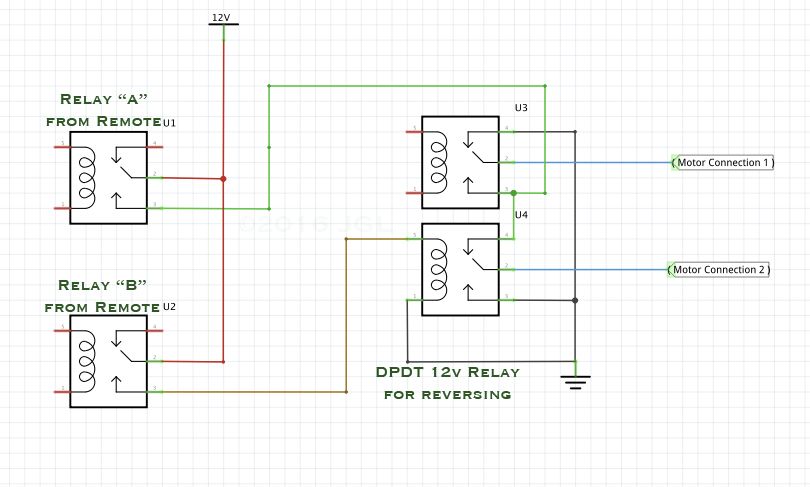
As a note I couldn't find a DPDT relay symbol on the program I used, so I stacked two relays to represent this. In effect it the same as two SPDT relays that turn on and off at the same time, so you could go that way as well.
Moving on to more complex solutions, for about the same price you could continue to use the single button remote, and add a $2 Arduino and a 2 channel relay board. With the right programing you would have operation of button pushes of "Push- On(forward), Push-off, Push-On(Reverse), Push-Off." (As a note, this could also be done with discrete circuitry or some latching relays, but the Arduino is just way simpler.)
Costs are about the same either way, just depends which you like better, two buttons or one.
JGL
(Edited error in relay naming from DPST to SPDT)