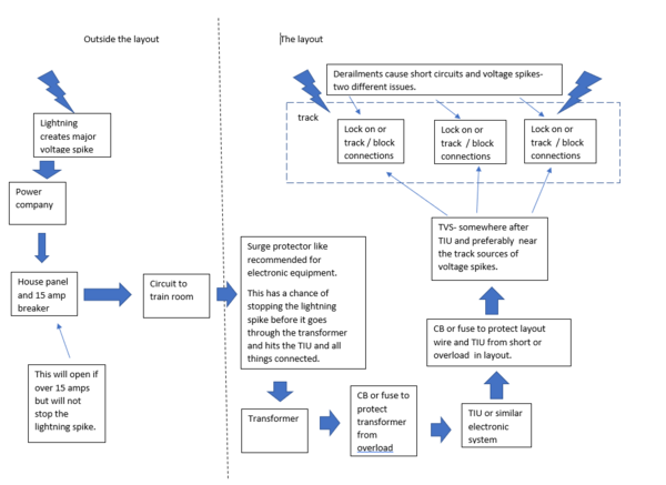
Sorry to beat a dead horse but have two buddies getting their Rev L repaired now. I understand adding the breakers between my Z4000 and the TIU to protect from that end (I may get the PSX AC) but on the output of the TIU between the track drop down terminal blocks, I see various recommendations that I could use a little clarifications from you experts:
- With the breakers before the TIU, is there a need for additional breakers after the TIU?
- With the breakers before the TIU, I understand the idea of adding another TVS after the TIU, between it and the track drop down terminal block but is there such a thing as a resettable TVS diode? If it blows, you have to diagnose somehow and put a new one there?
- What size TVS would be recommended?
- I hate to wrap a TVS around the inputs to each terminal block around the table since you are crawling around under there to find a problem but is that the way to install them versus just four on the output of the TIU posts?
Thanks guys.
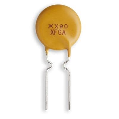
I have used this method (only half-wired in pic) for each power drop to my Legacy/DCS layout (about 20 in all) and have not experienced an issue with degradation of the DCS signal anywhere. If you solder the TVS to the terminal block before installation, it's a snap.
I've always understood it like this.
A TVS suppressor (actually, redundant since the "S" stands for suppressor), is a "transient voltage" suppressor, which protects against over-voltage conditions. When the TVS senses such a condition, it tries to send the excess voltage back to its source in order to protect the device in front of it. When that happens it's likely the TVS is no longer effective and should be replaced.
A fuse or circuit breaker protects against over-current loads and when it senses an overload condition, shuts down the circuit (either by breaking the metal strip in a fuse or tripping the circuit breaker closed) so you don't end up frying your electronics or welding the wheels of your Big Boy to the track.
So, basically, the two kinds of devices (TVS vs. fuse/circuit breaker) are protecting against different kinds of faults/failures.
The speed and ratings at which these devices operate is variable.
If I'm wrong, well it wouldn't be the first .............