I was thinking you could see how many were following a thread, thought I had seen that somewhere, but I can't seem to figure out how to do it now? I follow it, but you are so far ahead of me in layouts and modeling I mostly just listen (read) and don't often comment. I learn more by listening than I do by talking. ![]()
I would look at the number of individual posters for your guess at the numbers.
There are 25 alone, who "liked" the topic. I bet the majority have the alert on.
In addition, I'd bet out of the individual posters, a great number did so to compliment you, and as a quick way to turn the alerts on.
The number of "browsers" that are out there, and regular????
Lots of folk don't bother with the likes.
I read here on OGRF for near two years before joining.
I'm sure the number anonymous people interested, far exceeds the aperrent
I've noticed a trend lately on various Craigslist cities, FB, and other sites as well, for folks giving hobby classes, and/or individual tutoring. One here in Michigan is specifically for layout scenery! An occasional 1/2 day-3day (monthly, quarterly?) workshop group, seems like an easy way to pull in a few bucks, have fun, meet people, and dabble in your old work, your subject, on your time, your way, at your leisure.
I attended lots of classes like that starting as a kid. Really enjoyed them. One guy, had a balsa glider class, and only seemed to know how to say "harder, "softer", "thinner", "no", "watch" and "see?". He just sat there watching us, while building his, from the giant blue print. We watched him, and copied him. I fell asleep a couple times it was so quiet, but I almost set a record with mine too![]() . Stepdad disapprovingly crushed it a few years later.
. Stepdad disapprovingly crushed it a few years later.![]()
![]() Real nice!
Real nice!![]() . Man that thing sailed
. Man that thing sailed![]() .
. ![]() ...When does class start?
...When does class start?![]()
It's funny, I said that I could modify the thread title, but realize that you probably can't without starting a new thread. I don't want to do that since this is one continuous journey (IMHO).
Running clinics could be fun, especially since I'm putting out a lot of know how, experience and hard-knocks learning for free. On the other hand, I kind of like just building my stuff in the daytime and posting about it at night, without any responsibility to anyone else. I spent over 40 years in the working world training others and accepting responsibility for the competence in the organization in which I worked. It's nice to be really retired.
Back to construction.
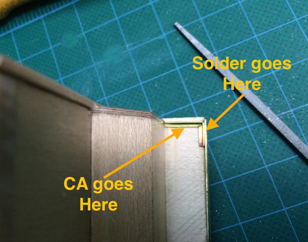
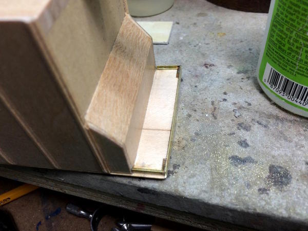
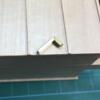
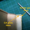
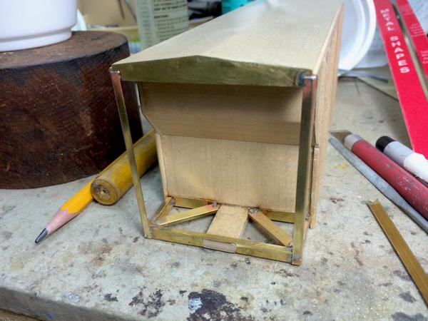
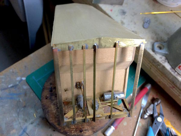
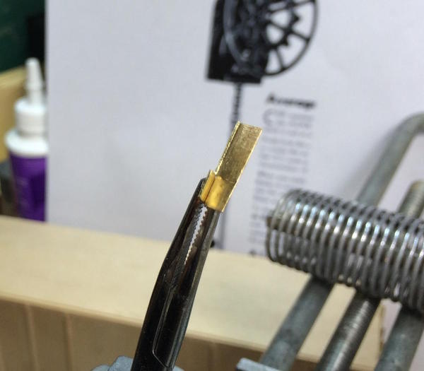
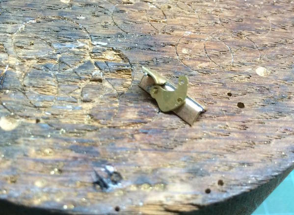
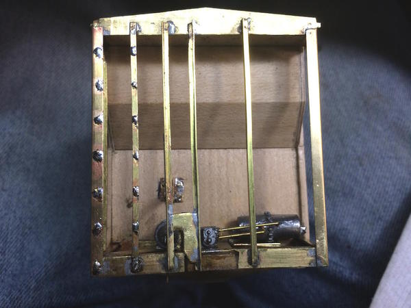
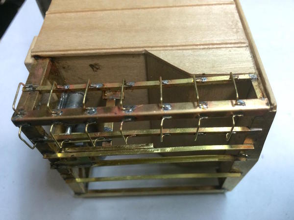
The end caps were cured, that is until when filing the ends to fit, it just popped right off. It seems the epoxy held on the brass nicely, but didn't hold so well on the wood. I blame the sanding sealer which has sort of a waxy finish. I used CA and got it stuck back on. I then put the upper side pieces on. I used my new method by taking a small piece of angle, cutting a thin slot with the razor saw down to the web, and then using a square jeweler's file, file a 90 degree notch that will let the angle fold to a square corner.
This provide a nice "tail" that greatly increased the soldering surface area. Here's the piece installed.
The first couple were a little tricky until I figured out to tin the angle before putting it position and then sweat soldering it in place. While holding the RSU tweezers on the joint area, I used a regular tweezers to hold down the other end so it was in contact with the model when the solder cooled.
Here are both sides completed.
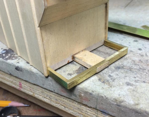
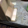
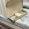
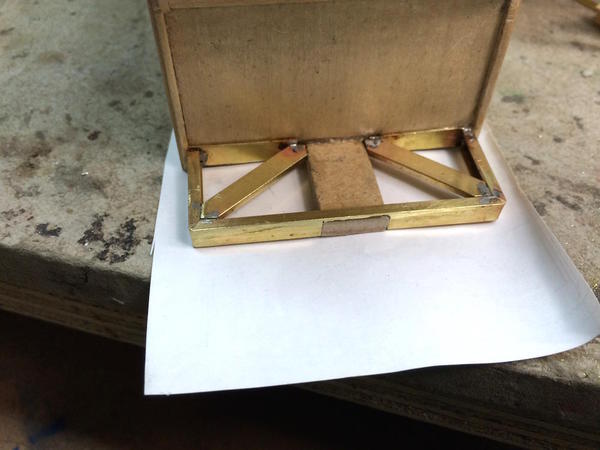
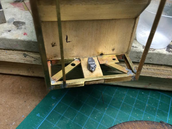
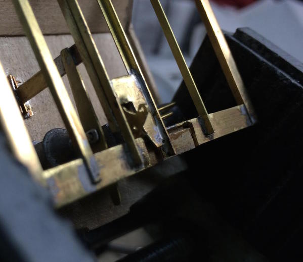
With the top pieces in I started to build and install the bottom frame. Using a larger size of channel I did the same thing: cut a slice down to the web, file the square opening, and fold. Here was the first attempt tested for fit.
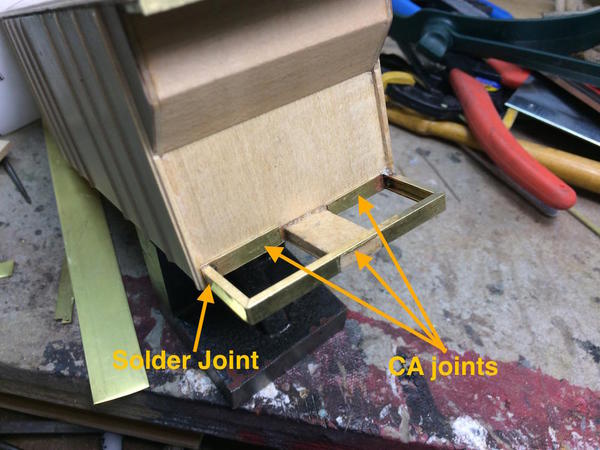
Notice also the large slot cut so it fit over the couple mount extension. In order to fasten this structure to the wood I added brass plates to extend the gluing area.
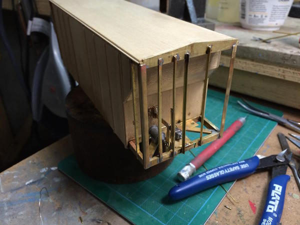
I got both ends fitted and mostly CA'd. I'll finish this out tomorrow. The ends are square vertically which corrects the problem I had with the Airslide Hopper. Without solder on the outer corners it will make it easier to solder the vertical angles at least on the bottom members. There's still a solder joint up top, but if I can get in and out quickly enough, that joint should hold.
Attachments
Wow. the attention to detail is superb. This is great. A work of art. Yet again.
Didn't do much today, less than an hour. So I was able to start installing the big diagonal end braces on one end. Having the brass plates at the back of the sub-frame enabled me to solder both ends and get a nice strong assembly. In the Airslide, I had to use CA on the back end and I'm not happy with that.
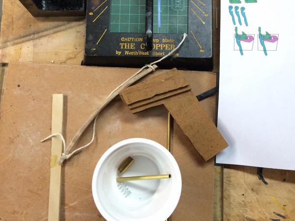
Yesterday I worked with #2 grandson on a science project: a miniature cross-bow. He came up with the plans and did the research on it. We made a pattern and cut the stock's pieces out of 3/16" Masonite. In this way, the hole for the trigger mechanism could be built in instead of cut. We'll round out the grip which is why the excess material that was glued on. It's about 1/3 size and will shot some kind of foam tipped dowel.
Our first attempt to make a bow wasn't successful. I thought if we laminated 1/32" aircraft play (7 layers) in a curved mold, it would make a good bow. It made a good bow, but it was completely rigid. When we attempted to bend it, it started to delaminate. I realized that the extremities couldn't be glued. So we made a second one and just glued the middle 3/4". It was quite springy and should worked when the ends are tapered.
He found a diagram on the Web of the "Chinese style" cross bow trigger mechanism. When he showed me his trigger design, it was missing a latch to hold the string in a cocked position until the trigger was pulled. It was missing a "sear" to latch the trigger. The Chinese style trigger has a sear that latches the string release until the trigger moves the sear out of position. I imported the diagram into Adobe Illustrator and then drew the individual pieces including locating their pivot points. I then scaled it down to fit the opening we built in the stock. We'll glue these drawings onto brass and cut them out. We may or may not put a spring behind the trigger.
He commented how cool it was to live so close to his grandpa who has a shop where all these kinds of things can be built.
The kids are coming over this weekend. #1 grandson's F-22 decals arrived from the importer so he'll get back to work finishing up that jet. The set that came with the model kept disintegrating and drove him crazy. They had to get a new set from Japan. It was a Hasegawa kit. #2 and I will work on the cross bow and I may sneak some RR work in.
Attachments
Trainman,I just wanted to jump in and say that I get on your thread once a week or so to see how you are coming along.I have learned a great deal and you have inspired me.I also want to thank you.I know it's an incredible comittment to document all of your accomplishments.Nick
Just wanted to let you know I added you to the Inspiration Thread with some of the best modelers on the forum.
Hope we can meet sometime in person. Wife and I would have went to the train show in Louisville a few weeks back but weather didn't cooperate.
Your feedback and comments just making the documenting of these projects all the better.
I am flattered that you feel me in the same caliber as the others in the Inspiration Thread.
Did some more work on the grandson crossbow project. After tracing the actual Chinese trigger mechanism in Adobe Illustrator I separated them as individual pieces plus kept the assembled diagram to set the hole spacing. Pasted the individual pieces onto .030" brass and used the jeweler saw to cut the pieces out. Before cutting we drilled the pivot holes. After a little clean up, the pieces are ready to be assembled into a a working crossbow trigger. I printed the diagram out at 1/3 full size. I'm not supposed to be building the entire thing so I stopped there.
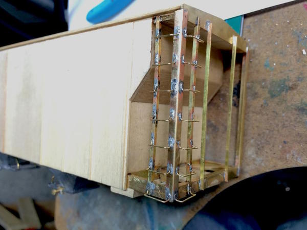
Today had a full work session and got some more brass framing done on the covered hopper. I'm using a larger size of angle for the corner pieces. I've noticed that many hoppers have heavier angle in the corners. I also got the remaining diagonal braces fitted and soldered.
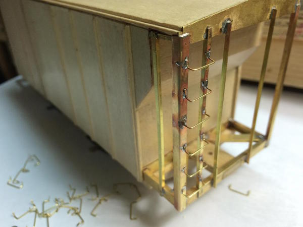
Since I'm building the ladders from scratch I soldered additional smaller angle spaced appropriately from the corners. These are assembled with the angle facing inwards so the ladder rungs fasten to the face. I'm even exploring forming the ladder rungs so they have the lugs on the bottom like the prototype which will be face soldered. I'm not looking forward to drilling all those equally spaced holes.
The more I do this, the cleaner the solder joints are becoming. I'm sweat soldering as many joints as I can. For the uninitiated, this is where you apply so solder before assembling, put the parts together, and then apply the heat. With the RSU you keep the switch on until you see the pieces settle together and evidence of liquid solder peeking out of the edges. I makes a strong joint with very little excess solder to clean up.
With the ends still open it's again time to install the brake rigging. This time, I'm not using the kit's floral wire, but substituting .032" brass wire. I also prepared all the locations with drilled holes to accept the lugs on each of the brake casting. I also soldered a flat plate so support the air reservoir. I'm also correcting an error I made on the last car project where I put both air reservoir tube holes on the same side. They should be on opposite sides of the center seam.
These aren't epoxied in yet. I still have to prepare the brake cylinder for the piston rod. I think I'll do the brakes like the last car. Building the car as a wood/metal hybrid makes a pretty good project and it's quite strong. Three more angles go on the brake end and two on the other.
I ordered some fresh decals and Modeltech paint from Walthers that came today. I'm going to make the Airslide into a mid-80s Burlington Northern car, and this car a Santa Fe car. The kit decals are quite old and I didn't trust them. For those that don't know, Modeltech is produced by the Badger Air Brush Company, and is the most odorless water-based model paint I've ever used. It's hard to find, but Walther's has all of it.
I also have lots of rivet decals left over from the bridges project and may apply them to strategic locations on the cars.
Attachments
Reading about your older decals made me think of the stuff I used to use on model airplane decals. I believe it was made by micro-scale. Can't remember for sure, been 25 yrs ago.
Basically it was a liquid decal film which when dry, kept old decals from 'dissolving' when put in water. Worked like a champ, saved me many times.
I even made some of my own decals using it.
I'm sure something similar is made today. One bottle will treat a lot of decal sheets.
I do have the Microsol decal coating and used it on the kit's decals as a precaution. I figured that if i could get new ones, I would use them and hold the old ones in reserve. I found a set on Walther's that I'm going to use. It's a Burlington Northern set so I'm going to paint the car BN green. The only problem I may be facing is the set I bought was for a 50' Airslide and I'm modeling a 40' car. I will try and make it work.
For the covered hopper I bought a set of Santa Fe decals instead of using the imaginary set that was in the kit: Scalecoat Paint. Quality Craft was being cute including decals for their model paint line.
I used future floor wax on the set of Hasegawa decals with my grandson's F-22, but the acrylic wax soaked into the decal film and changed their color. The importer sent a new set under their warranty.
That is really some exceptional modeling, what an eye catcher. Great work and thanks for sharing it with us all. ![]()
Many thanks! I really enjoy posting the construction.
Did some brake work today, and what a nice day to work in the shop with the rain and snow coming down outside. Louisville is getting a rare, one-foot snowfall in March.
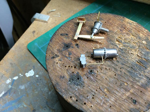
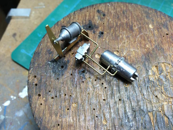
I built the swing arm a little differently in this car than the last, making up a set of angle brackets to trap the level. This was soldered with the RSU. I made another tubular aluminum air piston rod and saw cut a groove in it to act as a clevis to trap the middle of the swing arm.
I was having trouble holding the brake parts still so I could fit the 0.032" pipes, so I drilled some holes in my old oak work block and set them up in the same orientation as they are in the car. This worked better. I was able to get all three pipes properly fit.
Pipes are not glued in. I also realized that the triple valve must be stationary to properly fit the other pipes when assembling in the car. It was driving me nuts that it was rotating all over the place as I was trying to get everything trial fit. So I epoxied this in first and let it set overnight. Tomorrow I'll install the other two components. The out end of the upper brake arm gets soldered to another piece of angle which also forms one of the two vertical supports for the manual brake wheel.
Attachments
I'm not digressing into a car discussion again, but suffice it to say that the Avanti was one of my favorite designs and Raymond Lowey my inspiration of industrial designers. As many of you readers may remember, I went to Michigan State to become an industrial designer.
Good work session today. Finished up the framing, brake machinery, center sill, bolsters, train line work, and truck modifications.
Installed all the brake machines. I decided to increase the strength of the joint holding the brake support arm to the car body by drilling and soldering four pieces of .032" brass to act as pins to give more gluing surface. I then added the front support member. I made the brake arm 1/16" too short so instead of overlapping the support, it just touched it. I added another piece of angle behind the framing member to give a surface to which to solder the brake arm. I used CA to hold the brake cylinder and air reservoir to the frame, as well as holding the bracket to the car body, but all the other joints are soldered.
The reservoir was annoying to get the tubes into place. I finally resorted to using a forceps to hold onto the reservoir and keep it from bouncing around while I fitted the tubes. Once everything was in place I applied CA to the tubes and the reservoir.
There were lessons learned from the last car. One was to be meticulous in spacing the two framing members that support the Ajax brake mechanics. In the last job, the spacing got away from me and I had to solder a backing plate into the frame before installing the Ajax. In this case, I used the Ajax as a spacer, holding it in place with my fingers while heating the pre-soldered joint with the RSU. It worked.
Here's the non-brake end's framing.

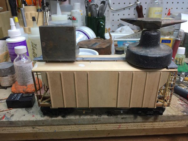
I cut the center-sill to length based on the plans by cutting the excess off in the miter box. I sanded the ends square with the Precision Sander. I had measured the center of the car, and put a center-measure on the sill. I used Aleen's Tacky Glue and some small quick clamps to hold it in place.
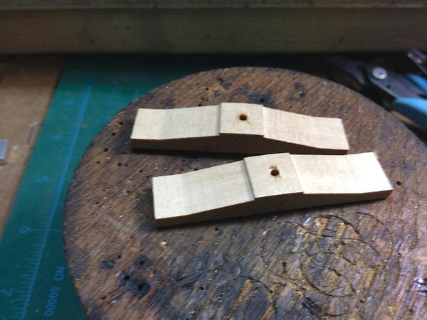
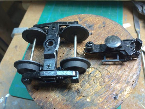
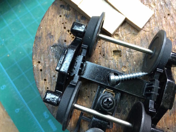
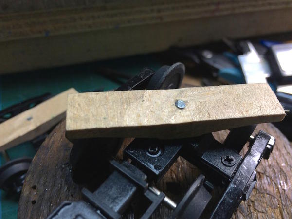
While this was drying I prepared the trucks and bolsters. In the last car, I drilled the bolsters when they were already on the car and drilled right into the back wall of the hopper bin. In checking the hole placement in this model, it looked like that could happen again, so I changed my plan. I drilled the hole off the car in the drill press, pre-threaded the hole with the #6 X 5/8" sheet metal screw and then hardened the threads with thin CA. This is a technique the RC aircraft guys to to strengthen screw threads in wood where you may want to take the screw in and out. The big couplers have to go and the remaining lug is cut off so the truck doesn't foul the Kadee coupler box.
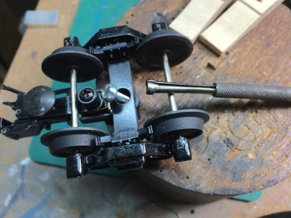
I remove the plastic air hose and use it on the car's train line. The sheet metal screw head is about .030" too big and needs to be turned down to .234". I use the lathe for this, but you could just as well by chucking the screw in a portable drill and running it against a file held in a vise. The device leaning against the truck is a Starett small hole gauge. It has a screw inside that pulls open the spherical jaws to contact the edges of the hole you're trying to measure. You then use a micrometer or digital caliper across the end to read the hole's size. I first tried to measure the hole by the digital caliper, but it wasn't seating well and I was getting variable reads.
Here's the turned screw.
I also realized with the last car that the screw is so large and strong that you don't need many threads engaged to hold on a model train truck. So in this case I threaded the screws through the truck and bolster and then ground off the excess threads.
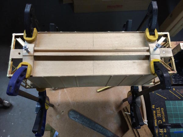
With the sill dried I fit the bolsters to the car. They were both a little bit wide and had to be cut down. After that I glued them to the car and clamped them with quick clamps
While the bolsters were drying I prepared the ends of the train pipe with the pieces of air hose from the Atlas trucks. Another less learned. It was difficult getting the airlines on the piece of floral wire in the last car since the train line was already glued to the car. I also carved the plastic air line to fit around the wire. This time I ground the wire flat to provide gluing surface and I prepared everything off the model holding the wire in vise. Using a spring tweezers, I held the two pieces in place and then applied thin CA.
The results was a much cleaner job. Again I wrapped the joints with twisted black iron wire so they won't come loose in use.
Tomorrow, I'll start working on the hand-made ladder and grab irons. If I finish that I'll install the cast hopper discharge chutes and the roof walks. The model should be done some time next week.
Meanwhile, my design work continues on both the distillery and a scratch-built coal mine based on the article in the December 1976 Railroad Model Craftsman.
Attachments
Today was an excellent day to be in the workshop-Louisville had some snow last night!
This morning I saw all the UPS planes that couldn't get into Louisville sitting in Indy. UPS planes sitting everywhere.
Although it was a perfect day to work on train stuff, since both grandsons had a snow day, my time in the shop was primarily working with grandson #2 on the miniature cross-bow project. When they left late in the afternoon, I did get one thing done on the covered hopper. I wanted to fabricate a more prototypical hand brake mechanism. The upper end of the Ajax hand brake is a a pair of white metal castings for the gear box and the hand wheel. But the lower end is completely un-defined. I pulled some stuff off the web and created a facsimile of the bell crank mechanism that converts the up-and-down motion of the chain and rod to a lateral motion in line with the car's brake cylinder and rigging.
Here's the brake rigging done up right. It's a picture of a Proto:48 Protocraft Ajax unit. It's all lost-wax castings which I cannot do. I seriously thought about spending the money and buying this Protocraft part, but my practical half decided against it since the rest of the model is not up to this standard. For example, I'm not detailing the under-carriage. I'm not embossing every rivet, nor am I hand-building out of brass the bottom hoppers and working outlet gates. I'm making "Standoff Scale". In model RC aircraft parlance, standoff scale is a model of a real object that is best viewed from 6 feet away.
Frankly, I don't know how companies like Protocraft and Precision scale do their work. Do they make the master in a much larger size and then use pantograph or NC machines to produce the miniature, or do they carve the parts in 1:48 directly out of the wax? I'd really like to know since making parts like these out of brass stock in scale is very, very difficult. Clearly, the real bell crank is a steel casting with lots of 3D definition. I made my bell crank 2D.
Here's another picture showing the actual layout on a typical hopper car.
And here's the mechanism on an N&W coal hopper car.
The hand brake and the cylinder are aligned so they both act on the same point on the brake lever. Unfortunately, I didn't have this drawing when I mounted the cylinder to the car's frame and they aren't in line. No one will care.... but I know. The first thing I need was a mounting bracket upon which to hold the bell crank.
You'll notice that the hand brake mechanism is mounted on "z" channel. The channel is then offset towards the middle to be at the proper distance to support the bell crank.
I fabricated the mount by soldering a piece of 1/8" angle to a flat piece of brass cut out so the crank had clearance. Instead of using tin snips which curls the heck out of the parts being cut, I used my hand nibbler. It's great for making square internal cuts. You have to clean the nibbled edges up with a file, but it makes for little distortion. I soldered the two pieces together holding them with a hemostat. I used 60/40 solder for this and then used lo-temp TIX to mount the plate to the car.
I hand-sketched the bell crank on a piece of .026" brass, drilled the holes and then cut it out with a fine-toothed jeweler's saw.
The bell crank is held to the bracket with a 0.032" brass pin. I soldered the pin into the bracket an then squished the end with a plier to retain the bell crank.
Here's the assembly soldered in place onto the car body.
Using the lower temp solder prevented any of the other nearby components from de-soldering. While the hand brake is not in line with the cylinder, the bell crank is in line with the hand brake wheel. In order to mount the cylinder more to the right (in this picture) would have entailed making another mounting plate like I did for the reservoir.
I would really like to find an "easy" way to make miniature clevises to connect round rods to moving parts. I think I will add the cut levers, even though the Kadees I'm using don't have provision for actual uncoupling using them. Protocraft does have scale-sized type E couplers that do open using a cut lever. Like I said, if you want to go high scale, there's many more things you have to do. And then, this car would look completely out of place with my 50 (or so) MTH, Atlas and Lionel O'scale freight cars with their enormous couplers, plastic ladders and lack of brake detailing.
Attachments
Ray,
Your level of paying attention to detail is great. Everything you construct is excellent.
Alan Graziano
Alan, considering the level of your work, I greatly appreciate your compliment. We have a mutual admiration society going...
But really, how do companies like Protocraft and PSC make their brass detail parts? I'm fully conversant with the lost-wax process, but it's making the masters that puzzles me. Input would be terrific.
Well... I just did some research and it seems the 'modern' way to do lost wax is to 3D print the wax mold and then investment (lost-wax) cast it out of metal. So... you take a 3D scan of the prototype object, scale it to 1:48, print the wax model out on a wax, high-precision, 3D printer and voila, a perfectly created scale component in brass. All it takes is $$$$$$$.
Not much time to work today, but did spend some time at the local hobby shop. What time I did have was just enough to take a "simple" step and make it much more complex. I hate when that happens.
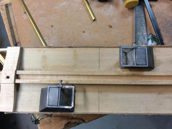
I decided it was time to add the output chutes so the model could sit level on its bottom. This consists of 8 parts: four shaped castings representing the hopper bottoms and four casting depicting the hatch assemblies. To this you have to add 2 diagonal supports to each. They are right and left configurations.
Here's the first thing i screwed up. Can anyone guess what it is?
The left hand hopper's hatch casting is CA'd with the lug facing the wrong way. I tried to pop this off, but it was super-glued REAL good! I will scratch build another lug and add it to the outside. That was the easy one.
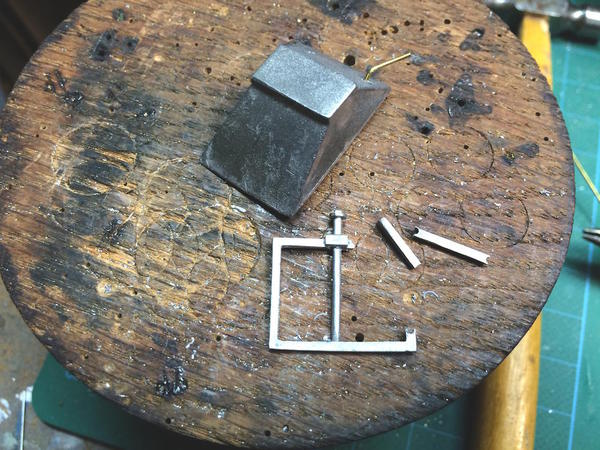
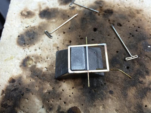
This one is a little bit harder. This was the last of the four. After manhandling and bending the .032" brass wire, the hatch mechanism was distorted. It's white metal and does bend easily. This was the result when I tried to push it back into square.
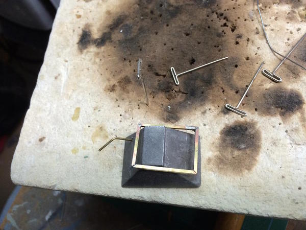
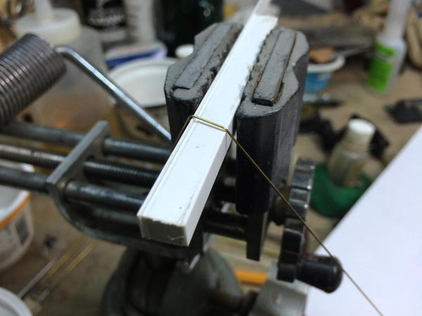
Now I had to scratch-build the entire mechanism. I decided to form the frame out of 3/32" brass square stock. Like I did with the channel frames I cut a notch with the razor saw and then open up the notch using a square jeweler's file. This lets you carefully bend it into a square rectangle.
After bending I soldered all the joints.
The frame is slightly out of square, but it will suffice.
I then laid out and drilled for the cross-shaft. I drilled for a .032" brass rod to which I added a piece of 1/16" aluminum tubing to bulk it out. I'm going to turn the outside piece after I solder a piece of rectangular brass to the tops representing the wider portion of the frame.
So a relatively simple step turned into a two hours of work and it's not done yet. I do hate when that happens.
Attachments
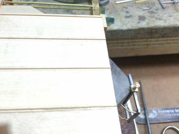
Another two hours of work and I finished repairing and restoring the hopper's hatch mechanisms. I turned the operating lug on the lathe and then squared off the four sided wrench point with a swiss pattern file that only has teeth on one face. I also clipped off the one that I mounted backwards, machined another operating lug for that one and put it on.
Here's the finished frame with the lug soldered on.
For the enlarged area I drilled and cut a piece of small Special Shapes brass channel. I also had to add the same kind of piece on the backwards one. I did an experiment the other day and found that I can solder to this white metal. I was frankly, surprised! I used the TiX 275° solder just in case this stuff melts before the solder did. With a successful test I drilled the errant casting (.032), soldered a short piece of same-sized brass rod into the hole, soldered the channel on top of this and then soldered on the lug.
And here's the four outlet chutes finally CA'd into their final position. Phew!
Next session I'll again start working on the ladder rungs and all the other grabs.
Attachments
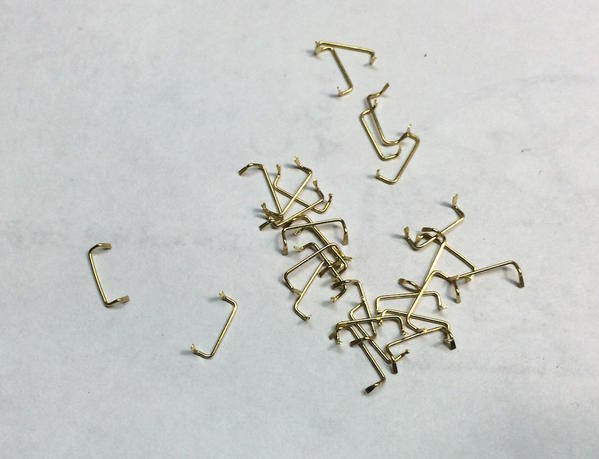
Started installing grab irons. My intent was to make drop grabs for the ladder and straight grabs for the rest. I'll describe the total process here, but suffice it to say that I really didn't get the shape right. My first practice piece was shaped correctly, but I didn't realize it and then simplified it a bit and made 28 more.
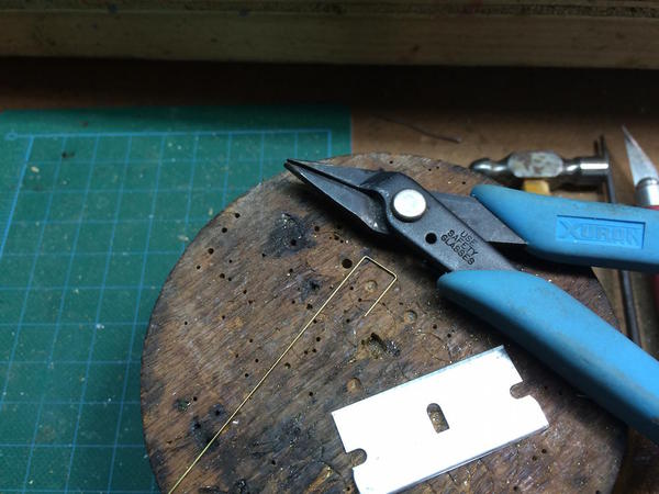
I measured the distance between the two uprights and produced a bending jig that was laminated of several pieces of styrene. The first go came out a little narrow, so I added .020" more and it was right. I don't make the full bends over the jig; just get the bends started. MicroMark sells an expensive bending jig for making grabs. This one was much less expensive!
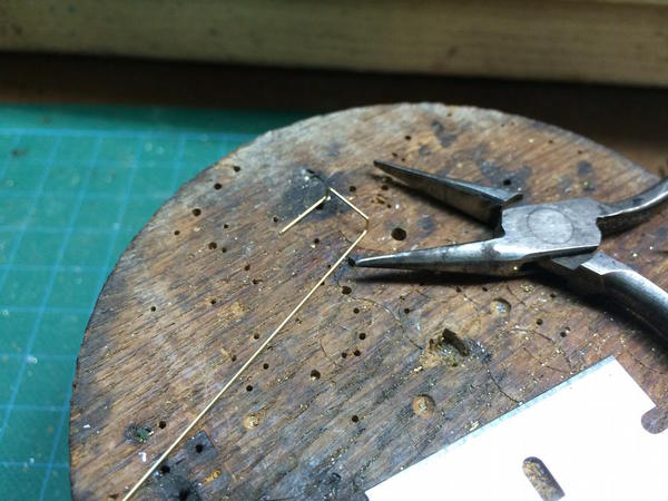
Using my Xuron needle nose, I complete the first bends making sure they're square and in the same plane.
Using another pair of needle nose pliers that have a smaller tip cross-section, I make the second bends. This is correct for a drop grab.
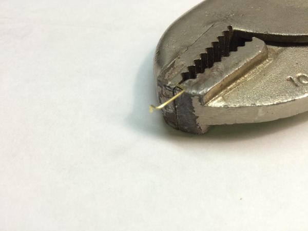
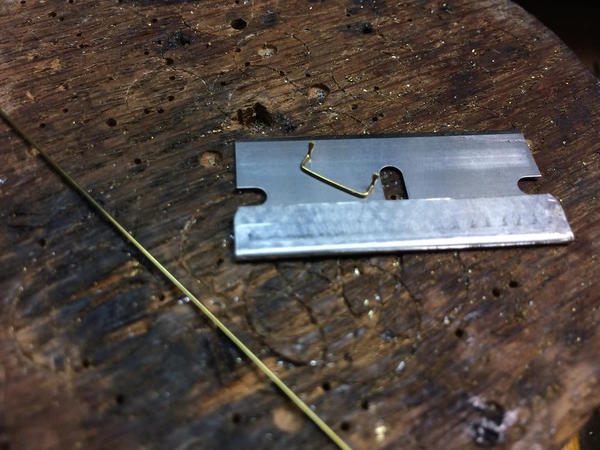
To be authentic, there should have bend another 90 degree backward facing bend, but I chose not to add it. Instead, I clipped the ends leaving a tail. Using my trusty vise grips, I then squash the ends to make the flat surfaces which will be fastened to the model.
Here's a completed grab.
And here's a whole gaggle of them.
To fasten them to the model I measured off each location with the digital calipers, and then put a small drop of tinning at each spot with the RSU. Continuing to use the RSU, I stabilized the positioning of the grab with the needle nosed pliers, gripped one flat end with the RSU and heated the joint. When secured I no longer needed the pliers and moved to the other end and finished the job. I really didn't know what to expect in this step since the needle electrodes on my RSU are getting pretty blunt (I've ordered more from MicroMark) and I was afraid that I couldn't get a good purchase on this small part. I was wrong. The soldering went quite well. By surface mounting, I didn't have to sweat drilling a raft of .020" holes in the thin angle. The corner angle wouldn't be a problem, but the thinner angle would deflect when drilling and I wouldn't like the result.
While not exactly the correct geometry for a drop grab, I'm thinking that I'm not going to pull them off and make another 28 in a different shape. To me, they look authentic and much better than the cast ladders with the wrong kind of rungs entirely. The only thing missing is some tiny NBW castings at each flat. I've got some really small Tichy NBWs and if I'm feeling especially compulsive (more so than usual), I might attempt to put them on.
For the adjacent set of rungs, I'm going to have to use the lower melting point solder since heating the same spot will un-solder all the good work. To me, nothing jazzes up a train model better than handrails and grab irons. When I was 14, I drilled the brow over the windshields on my Lionel Santa Fe 2343s and installed my own grab irons. I didn't care that I totally destroyed the re-sale value of the engines. F3s HAD TO HAVE RAILING OVER THEIR WINDSHIELD....PERIOD! I also scratch-built an interior for the lead engine. Not bad for a kid in 1959.
Attachments
RSU amaze me each time I see work like this. Who'd think you could do this ? It erases all doubt I have about what I can do with mine in the future.
You car looks great.
I can't wait to see it finished and some more of your layout.
Yes, the RSU is amazing. It took me a long time to bite the bullet and buy one since I wasn't sure I would be using it enough to make sense. Instead, I'm using it on almost every project. It helps that I'm finding projects that involve precision brass fabrication. Today, although I only had an hour, I got the other 7 rungs on the first end of the car. I used 60/40 solder on the thin member and the TIX on the corner angle that was adjacent to the previously attached rungs. Generally this worked, but it wasn't without its difficulties. I was having that problem with the TIX where the solder melts, it looks like you have a joint and the part just fall off. There's solder on both pieces so it's not because it didn't tin. More than a few times the rungs on the adjacent side let go, but I quickly got them back on.
The most trouble was the bottom rungs. There's a lot of metal down there so heating was much slower. As a result I kept going back and forth as each side kept letting go when I was doing the other. Finally, out of desperation, I put the RSU tweezers on both adjacent rungs and heated them at the same time thereby causing them to both fuse simultaneously. Sometimes desperate moves work.
As far as seeming more of the railroad. I ran some trains the other night and made an iPhone movie. It shows the entire layout and it's pretty jittery.
It's uploading very slowly to YouTube. I will add the URL when it's completed.
Attachments
Did the remainder of the ladder rungs. My RSU learning curve is very steep. Literally each time I use it, I'm getting better results. This second set of rungs went on more smoothly with smaller solder footprints and with none of the redoes. I didn't use any of the TIX solder. Instead I controlled the "de-soldering" problem simply by killing the power the instant the solder under the rung melted. It's all over in about a second...no more. After finishing them I started adding the remainder. There's one on the lower right hand corner of the car frame and long ones blocking the large open areas on the right side.
In this part of the job, I really tried to control the initial solder amount. Before tinning, I used a small artist's brush to add some TIX liquid flux. It's a chemical that's good at breaking down the oxide film on the brass. I'm using rosin-core solder, but the TIX flux helps the action and speeds things along.
Even though it looks like a lot of solder is laid down, when the rung is in place, the wicking action when they join almost makes the solder disappear. This end of the car will require less cleanup than the first end.
Here's the full set of rungs in place. By positioning the RSU between the far edge of the big angle away from the other rung, and the lug on the rung I wanted to solder, I was able to heat the solder area quickly enough so its solder melted and fused before the adjacent rung got hot enough to de-solder. Only with an RSU can you do this. I don't know how people built brass locomotives before its development. If you ever want to build in brass, you've just got to bite the bullet and get one.
I'm really glad that I went with the surface-mount approach. They look more prototypical and I avoided drilling 28, #75 holes in the bendable brass. It worked so well that I used it for the remaining grab irons. The only area that I couldn't solder is where the grab irons attach to the wood part of the car. I didn't even give this a thought until I was measuring the bends. At first I though I'd leave that end straight and put it into a hole in the wood, but realized that I could CA the brass better if the ends were bent like the other side of the grab.
I ran out of time and didn't get the remaining two long grabs in place that are right angles to the ones I installed. I was going to bend all eight of them at one go, but found that the end grabs are shorter than the side ones. The brass is already tinned waiting for them to be bent. I tried making a more prototypical drop grab, but the distance between all the bends was too great causing them to stick out too far from the car so I went back to the two-bend method that works so well.
Attachments
I've put that new video up on YouTube at
It's a bit jittery. I used iMovie's stabilization function and I'd swear it made it worse. Live and learn.
I was just running some trains...
Great video! It was good to see the car running on your layout. Also, it was good to see the trains running again and your many projects you have so dutifully described for us!
Thanks Mark. I like to run the trains once in a while to let the spiders know who's boss. Say what you will about O'gauge, 3-rail, Ross track. If the trains haven't run in a month, you just put on the power and away they go. Try that with HO or N gauge. You'd have to first conduct a major track cleaning exercise to get rid of all the oxide. I've replaced the ni-cad standard MTH Proto 1 with LiMH's and they seem to hold charge for a long time.
Right now, besides the covered hopper, I'm making detailed laser-cutting drawings for the distillery main bldg and the side annex that's attached. Besides having to engineer all the joinery so it goes together like a Bar Mills kit, I'm also having to remove little line segments to serve as those little remaining tabs that keep all the laser cut pieces from forming a big pile at the bottom of the box.
I'm working with a couple of different folks to do the laser cutting. I'm thinking that once the drawings are done, it's not a far stretch to make it as a kit for others. I'm debating whether to laser cut all the bricks ($$$) or resort to more humble brick paper. I'd really like to add the brick work, but it could double the laser cutting time. I'm also thinking about making another one for display at either Heaven Hill Distilleries downtown Bourbon Experience or their visitor's center at their Bardstown bottling facility.
So true about this difference in not needing to clean the track as opposed to smaller scales. I am amazed, since I ran HO and N for over 40 years before switching to O.
The laser cut project sounds very interesting. You can put my name down as a buyer for a kit if you decide to go that route. I would consider it A prized model after conversing with you on modeling and other topics. I realize you may find it not feasible to do, however. Seeing what you come up with will be fun enough.
I will definitely consider it. There's obviously more in producing a kit than creating some drawings and laser cut parts, but I'm willing to give it a try. I'm getting frustrated by the choices we O'scalers have in kit selection. How many 1940s gas stations and small freight stations do we need? Bar Mills produces great HO stuff, but they skimp on their O'scale offerings. BTS has some brilliant stuff. If I do a kit, I probably won't be able to include any of the usual white metal castings. These are available from other sources. But the kit would contain all the materials to make the structure and windows and doors. Selling a kit could make laser cutting the bricks worthwhile.
I missed a day, but didn't work too long on Friday so you didn't miss much. Over the weekend #2 grandson and I finished up the working 1/3 scale crossbow with good success. We used the "Chinese Mechanism" vs. the "Mediterranean" mechanism. The Western crossbow used a rotating nut in the trigger mechanism which we deemed to difficult to produce for this science project. Three years ago his older brother and I built a "Jacob's Ladder" which was a huge hit. The crossbow has a cocking lever, a sear, and trigger with a pallet upon which the sear sits when the bow is cocked. It shoots about 20 feet and can put an "arrow" into a block of foam from about 4 feet away.
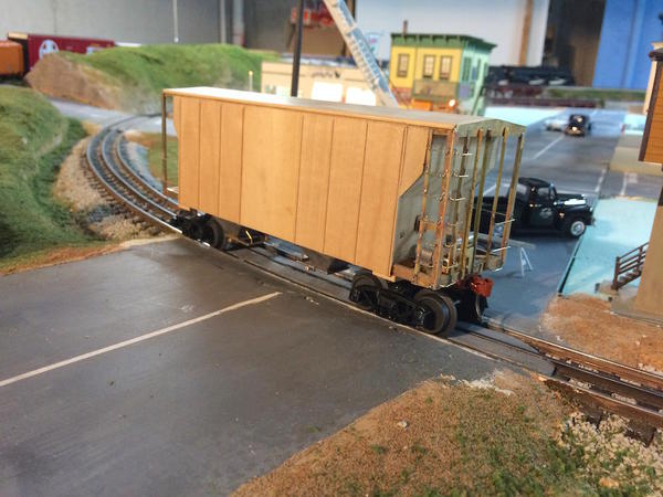
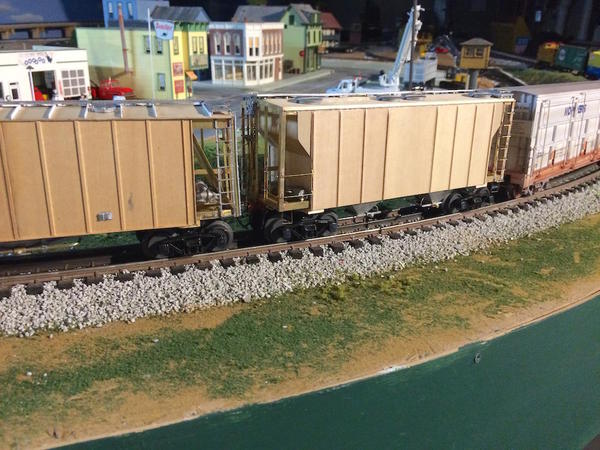
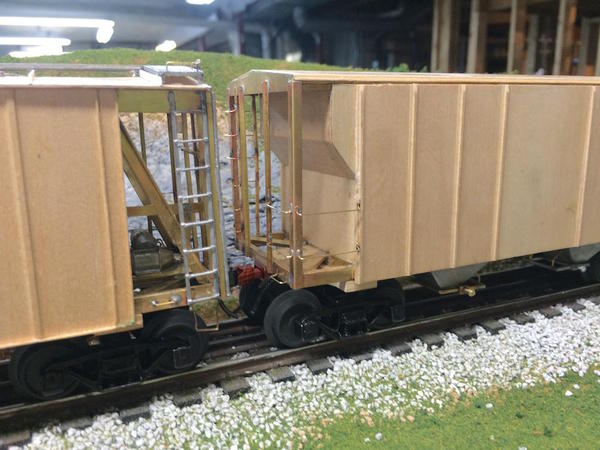
Today I got back to work. Since the last report I finished up all the grabs, mounted the train line, mounted the couplers, trucks and installed the roof walk with its associated mounting pieces.
Here it is now.
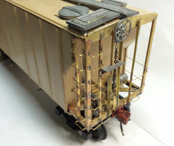
Here's the end grab irons in place. The hand built ladders look much better than the castings (IMHO).
I turned the model over and prepared to mount the Kadee couplers. An error showed up and the only way I can imagine how it happened. One bolster ended up being glued about an 1/8" more outboard than the other. It's not noticeable, but it encroached into the space for the coupler's draft gear. I had to carve out some relief in order to get the coupler into proper position.
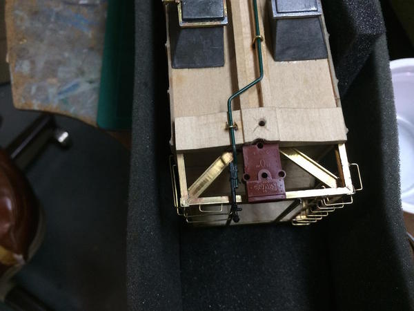
I suspect that it slipped forward under the pressure of clamp. I had spaced off the mounting position with dividers and it was the same on both ends. So for this bolster to be out of position, it occurred during the glue drying.
I then mounted the trucks.
The roof walk is held in place with some little shaped pieces. I was originally going to use the 1/16 X 1/32 basswood in the kit, but after attempting to shape it realized that styrene would be a better choice. The roof walks were assemble like the ones in the Airslide so I won't go into the details.
I laid out the location for the roof hatches and use medium CA to hold them.
On the pictures I've pointed out some holes (now filled with CA). I entertained the thought to solder the three pieces together. I put the RSU's electrodes in contact with the white metal and in a moment they melted right through. Back to using CA with brass reinforcements underneath. I thought I could cannibalize another couple of walks from the remaining kit I have, but it's an open-topped hopper and has no roof walks. So I'm making due with the perforated parts. DOH!
What's left besides paint? Put on the brake mechanism, corner grabs on roof walks, and corner stirrups, and that should finish it up.
Meanwhile, I'm putting in lots of computing time creating a set of laser cut drawings for the distillery. If I wasn't thinking about turning it into a kit, I would have been done already, but I attempting to engineer the kit a la Bar Mills et. al. with slot and tab construction. I'm also going to laser cut roof trusses and floor mounts so it will be easy to add floors. This gets complicated real fast. Every piece has to be cross-checked to make sure that it makes with all others AND that the proper deductions are made for pieces that fit inside others. And to make matters worse, I trying to put in all the brickwork. Boring!
The building has some truly fancy brickwork. And it has thick masonry walls. This makes it a challenge to deal with the corners. When you slot and tab a clapboard structure, you put in corner pieces to hide the tabs. In this case the walls are 3/16" so the corners are prodigious. The corners jut out from the main walls so I'm thinking about producing capping strips that you will sand a 45 degree miter so the bricks meet in the corner. It's a great learning experience. I'm thinking we'll cut the building out of the cheapest material possible before using real stuff so we can test out all the fits. I have great respect for the laser kit manufacturers out there.
Attachments
Decided the cast chain detail on the Ajax brake mechanism had to go, especially after I broke the little hole away from the rest when trying to assemble it. I decided to use real chain and see how it would work.
It's probably a tad over sized and if I'd do it again (which I will since I have one more car kit to build), I would install the chain up into the unit. As it was it was already CA'd to the car when the chain broke so I had to use some brass to link the chain to the Ajax. I then soldered three little brackets onto the car and then CA'd the work platform. This pic also shows the corner grabs on the roof walk that I also added today.
The last piece was the foot stirrups.
The instructions show the edge of the stirrup wrapping up the corner of the car. So in this first instance that's how I soldered it. But putting it on that way on the ladder side will not work well since it takes a lot of current to heat the big pieces of channel and all those rungs will melt off. So on the ladder sides I'm going to fold the stirrup under and solder it on the channel's bottom. Even with that, the chances of melt off are high.
I bought some new electrodes for the RSU and they really made a difference, especially when I had to put those little brackets on. I was actually able to hold the bracket in the RSU's tweezers, then touch the piece to the car, and heat it until it fused in one smooth motion.
Tomorrow, the remaining stirrups will go on the car and it will be mechanically complete. The weather's starting to show signs of stabilizing so it won't be long until I'm putting on primer outside.
Attachments
The magazines are missing out by not hiring you to do articles. I'm not talking about stuff you've done here-they ask you to scratch build an item and allow you to document it for their article. Many of your techniques are interesting and I've learned a ton just reading this thread.
IKt is a work of art, trainman. Really fantastic.
You're too nice. Maybe it looks like a Picasso...
It appears that I'm getting the substation published in a magazine so that's a start. ABB is interviewing me tomorrow to include the substation in their internal communications. So who knows where that can lead. And I'm designing the distillery to possibly be a kit for sale. So who knows where that leads too. So, even at my advanced age, things are very good and keep happening.
When you look in the dictionary for "late bloomer" my picture is next to it.
Finally! Some shop time. I finished up the foot stirrups on the covered hopper in a short work session yesterday. With that, the car is entirely finished mechanically. As soon as I get another warm day that's not a weekend, both cars will be premiered and painted their final colors and decaled.
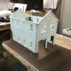
So I put the tools away and started the next project. The Westport Models Fire House. Les Lewis was going to market this kit, but I believe he didn't and I may have gotten the only one. I briefly talked about this a while back when grandson #2 and I were putting Plastruct structural shapes onto the walls to take out some warps. It's a resin kit and has all the strengths and weaknesses of that medium.
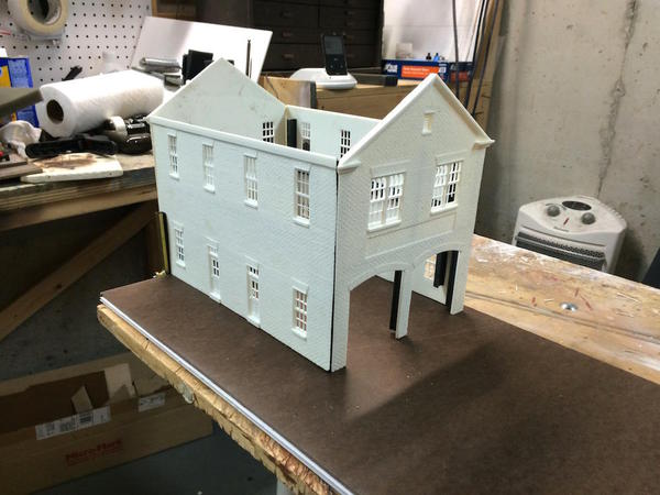
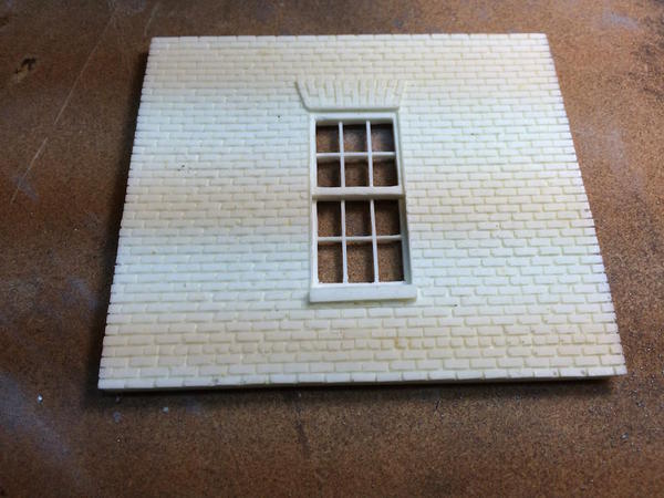
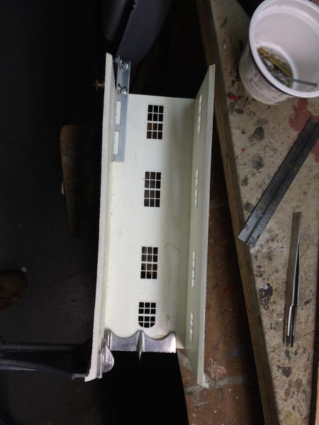
I made the base out of a combination of Masonite and foam core. It made it wide enough to park a fire truck along side, and deep enough to have engines parked in front without blocking the pavement. I just threw these three walls together to get an idea about fit.
This picture shows something unique about this model; the brickwork.
The bricks on the master were laid one at a time just as I did on the Victorian Station's chimney. That was small potatoes. Laying bricks on a building of this size was a monumental task. I actually ran into Les at York in 2007. He was putting bricks on this master and I was so impressed that I said that when the kit was done, I would buy one. I'm not apologetic for taking so long to get it underway. A lot of stuff happened during those intervening years including retiring, moving and building a railroad, but I am nothing if not persistent.
The walls are all beveled at approximately 45° so the bricks meet correctly in the corners. I had to dress the angles up on sandpaper glued to plate glass.
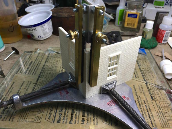
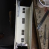
I found a miter clamp that was my late father's in a box of his old tools and put it into service on this project. After cleaning up all the windows, I started construction with the base of the hose drying tower that sits in the back of the building. It's four-stories high and is made up of a one-story base level and a three-story tower which sits on top.
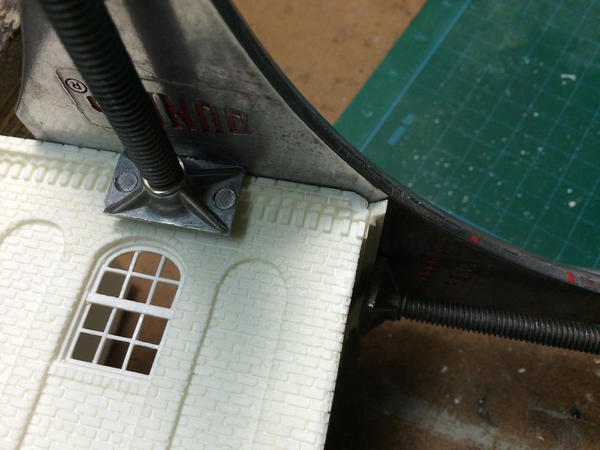
The miter squares one end. A corner clamp secures the other. Thees corner clamps (available from MicroMark) are really best used for HO-sized buildings, but can produce decent results in our large scale if given some assistance.
I used a spot of CA at the top and bottom and then remove the clamps to fill in the rest of the gaps. Les' instructions spelled out clamping the walls top-down so the mating edges for the upper section would be level. That left one of the bottom edges hanging too low. It was too big to sand off so I marked it and hit it first with the belt sander and then used the sanding plate to finish it up.
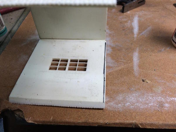
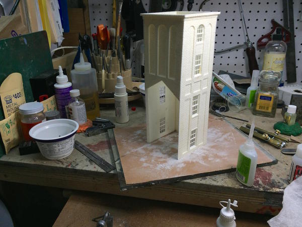
Using the same procedure I glued up the upper works parts.
Immediately after I took this picture, the whole deal fell on the floor, hit a top corner and knocked out a chunk. This project was going much to easily and I was rushing a bit. You always pay for that...
I used the CA/Rocket CA Filler Powder method to fill this gaping hole. The powder appears to be granulated acrylic and beside greatly adding bulk to the CA, it also has the effect of curing it almost instantly. After sanding it makes a very solid filled joint.
To further improve the repair, I re-scribed the mortar lines into the filler.
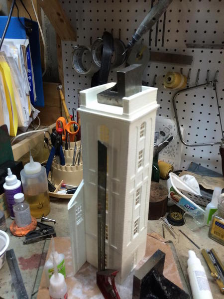
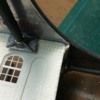
It was time to join the upper and lower sections.
The last piece to go on is the roof cap. The slant roof drains out to the left, not the rear as would seem initiative. I held the roof cap on with Gorilla Glue since the bottom wasn't entire flat. I attempted to sand it flat, and got it almost there, but got bored. Gorilla Glue is a polyurethane (like the resin in the kit) and expands on curing so it filled the gap.
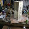
The piece flanking the front of the tower (away from camera), is the back of the engine house. It's a tricky fit into the tower's miters. I had to use the Dremel with a carbide router to trim it. In the process, I also stuck the thing into the meaty part of my left thumb. Again, I was rushing. That's when the bad stuff always happens. I washed it with alcohol, and bandaged it with some Neosporin. In a couple of days it will be fine... just a flesh wound.
If the weather's as nice tomorrow as forecasted I'm going to try and put some primer on the two railroad cars.
Attachments
Thanks for an excellent discussion of the problems and solutions with resin building kits. It is an interesting model but looks like a pain, actually; were it not for all the special clamps and all you have it would be a handful.
I think you're right! In fact, Les told me that molding the model was a pain too and it's why he got out of the business of making large resin kits. But you've got to admit, those bricks are sure cool. I'm working with Andre Garcia to laser cut the distillery. We're exploring doing the entire model with engrave bricks to simulate it's complex brickwork. To make all the castellated and Victorian details I'm designing laminated layers of 1/16" stock to simulate the stair step appearance of the prototype. If I can do the bricks economically we're going to produce more copies to make a commercially available kit. Big if...
Cool. Good luck. If it is a kit, I will certainly buy one - or two.![]()
While all your posts are good, I think the best are ones that show how you solved problems or corrected accidents and mistakes. It happens to all of us, but some of us have trouble making the corrections.


