After the long thread on weak DCS output signals from the TIUs there was some interest in a simpler tester for those that don't want to finance or support a full oscilloscope. Here is a really simple $10 answer (I priced parts at $9.44 on digikey... battery not included!).

DCS_test1

Concept:

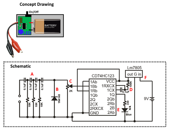
It's super simple. The filter [A] extracts the DCS packet. The offset diode [B] makes the voltage go between 0 and 12V (instead of -6V to +6V). The trimpot [C] is a voltage divider and makes it so the DCS amplitude needs to be about 12V to successfully trigger the one-shot. The one-shot pules a blue LED [E] for 1 second set by time base [D]. It runs off a 9V battery that's regulated. [F]

How to use it:

Connect the red and black wires to the TIU port. If the TIU port is good (Vdcs > 12V), the LED will blink. If the TIU port is weak/broken/bad (Vdcs < 12V) the LED will not blink.

I made a breadboard version and it works well. I'm a designer but maybe someone who's both a designer and good at making things (so basically GRJ) might do a pcb with a box if there is interest.

Attachments

Images (1)
  • DCS_test1
Last edited by Adrian!
Original Post

Replies sorted oldest to newest

Thanks for posting this!

So to set the trim pot, do we set it up on a TIU output we have reason to believe is good and just adjust the pot until the LED starts blinking?  Or is there a better method during construction (maybe applying a DC  signal directly to the B/C node of the circuit before installing the filters on the front end?)?

Thanks for all the good discussions you have been posting on the topic.

-Dave

Dave45681 posted:

Thanks for posting this!

So to set the trim pot, do we set it up on a TIU output we have reason to believe is good and just adjust the pot until the LED starts blinking?  Or is there a better method during construction (maybe applying a DC  signal directly to the B/C node of the circuit before installing the filters on the front end?)?

Thanks for all the good discussions you have been posting on the topic.

-Dave

Hey!

Yup, the trimpot just sets how many volts of dcs signal you need before the light flashes. If you turn it all the way up it’ll flash at 2.5V. In the middle it would flash at 5V. Near the top maybe 50V or more. I think it’s easiest to just tune it against a good channel like you suggest. Tune it to the point right where it barely flashes on a working channel, then leave it set there as your threshold of good and bad for future tests.

Last edited by Adrian!

I would like to try this out. Not sure I can make a PCB? If so that would take me some time, but I might try it anyway? Breadboard is probably what I will start with. I know GRJ can probably put one out in a few minutes. He may even have one posted here by the time I post this? 

My only question (I think) would be what type of caps did you use and were the resistors precision or just regular old 5% resistors? I am going to place a Digikey order for all that I don't have. Or maybe just order it all along with some extras.

Thank you again Adrian, for doing all this stuff and posting here for the rest of us. I find it all very interesting, make that fascinating! As I have said before most is over my head, but still very interesting and some may even rub off on me one of these days. 

Last edited by rtr12
rtr12 posted:

I would like to try this out. Not sure I can make a PCB? If so that would take me some time, but I might try it anyway? Breadboard is probably what I will start with. I know GRJ can probably put one out in a few minutes. He may even have one posted here by the time I post this? 

My only question (I think) would be what type of caps did you use and were the resistors precision or just regular old 5% resistors? I am going to place a Digikey order for all that I don't have. Or maybe just order it all along with some extras.

Thank you again Adrian, for doing all this stuff and posting here for the rest of us. I find it all very interesting, make that fascinating! As I have said before most is over my head, but still very interesting and some may even rub off on me one of these days. 

Hey!

The RC network at the front blocks 60Hz and keeps 1 MHz. Even if the values were off a factor of 10 times it should work fine. The filter as drawn cutsoff signals below a few KHz, but 10Khz or 100Khz is also fine. The r and c for the timebase sets the light flash at about a second. Depending on which version of 74h123 you buy the equation for the duration is different so you may want to try different combinations until you’re happy with it.

RJR posted:

Adrian, going to Digikey, I see many variations of the CD74HC123.  Why the differences and which is best?  Note Adrian asked a question about resistors & caps.

Hi again... I went with exactly this chip. There's no design reason, it was just in stock the week I needed it. All the people who make 74xx chips (TI, ADI, ON, ...) have different underlying fabrication processes for the CMOS technology so you get different timing numbers depending on which brand you buy. Again on the resistors and caps 5% should be more than enough. Everything is order of magnitude-ish insensitive so if you buy 1K,5K,10K,100K resistors and 0.01uF, 0.1uF, and 1uF caps, you will definitely have a few combinations that work. The only one that's critical is the one for the LED so you don't blow it with too much current.Note the LED doesn't have to be blue.... I just think they look fancy.

Engineer-Joe posted:

just to be clear here, you're just testing for +12volts out?

Most users will know if the TIU doesn't put out voltage. Is there a condition you're looking at that puts out partial voltages?

A meter or MTH PS2 or 3 engine could tell the user what the track voltage is.... right? or even a light bulb?

Adrian talks about DCS signal in volts not to be confused with volts used to run an engine. 

He should be able to explain it better

Engineer-Joe posted:

just to be clear here, you're just testing for +12volts out?

Most users will know if the TIU doesn't put out voltage. Is there a condition you're looking at that puts out partial voltages?

A meter or MTH PS2 or 3 engine could tell the user what the track voltage is.... right? or even a light bulb?

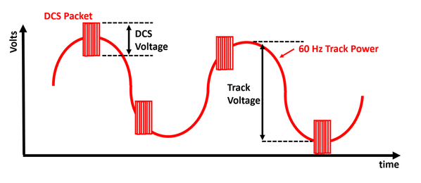
Here's a little doodle I made just for you!

voltage

The track has a 60 Hz voltage to power the trains (usually like 10-25V depending on what power source and such). It also has super-imposed on top of that the digital signal for DCS. We are talking about measuring this digital voltage, not track voltage. The digital packets are infrequent and at a high frequency which is why you need to filter them with the above circuit to measure them independently of track power.  It's this DCS digital voltage (formal name is excursion voltage) that limits your DCS link quality. A normal working part should have it about 12-14V, but when parts fail it can be a lot less. This is what the tester is validating.

Attachments

Images (1)
  • voltage

Digikey parts ordered! Luckily, I selected the exact CD74HC123E chip as Adrian linked above too! I didn't get the assortment of resistors and caps, but I have those in quite a few different values here in ceramic caps and 5% 1/4 & 1/2 watt resistors. Oh dear, now for the PCB design...eek! I think GRJ uses Diptrace, so I'll try using that. Maybe he will have mercy on me with this project if it's in his native language? 

What would be cool here is several LED's so you could see lower values.  If this were assembled by someone with a 'scope to calibrate it, you could have maybe four LED's to know exactly what you have.  What would probably be easy would be to create a circuit board for such a design with thru-hole parts so many people could build it.  With a 1% divider, you could probably do this kind of thing that requires no calibration.

gunrunnerjohn posted:

What would be cool here is several LED's so you could see lower values.  If this were assembled by someone with a 'scope to calibrate it, you could have maybe four LED's to know exactly what you have.  What would probably be easy would be to create a circuit board for such a design with thru-hole parts so many people could build it.  With a 1% divider, you could probably do this kind of thing that requires no calibration.

I like it ... but then you need 4 one-shots, 4 dividers and 4 leds to do it using this approach. If you only want one led at a time you need a thermometer decoder too.

If you're going to all this trouble you might just give up and and go to a microcontroller with an 8-bit ADC inside and a $10 LCD with numbers on it (like my telemetry train one). That's closer to a $50 solution though. At some point writing code becomes simpler than so much analog!

Everything I ordered was Thru-Hole so if I make it out alive after getting into Diptrace it will be something most anyone can make. I don't have a scope, nor would I know how to use it if I did so the calibration is a bit above me right now. I would be happy to add more LEDs, if I get something made up without getting spanked by the PCB part. 

I also ordered extras of each part so I could fiddle a bit with the boards if I get that far that is.

Adrian! posted:
gunrunnerjohn posted:

What would be cool here is several LED's so you could see lower values.  If this were assembled by someone with a 'scope to calibrate it, you could have maybe four LED's to know exactly what you have.  What would probably be easy would be to create a circuit board for such a design with thru-hole parts so many people could build it.  With a 1% divider, you could probably do this kind of thing that requires no calibration.

I like it ... but then you need 4 one-shots, 4 dividers and 4 leds to do it using this approach. If you only want one led at a time you need a thermometer decoder too.

If you're going to all this trouble you might just give up and and go to a microcontroller with an 8-bit ADC inside and a $10 LCD with numbers on it (like my telemetry train one). That's closer to a $50 solution though. At some point writing code becomes simpler than so much analog!

I'm not convinced that you really need four one-shots.  Why not a comparator ladder with four levels?  An LED will be visible with a very short pulse, so the one-shot may just be icing on the cake to make it even more visible.  I'd consider 3V, 6V, 9V, and 12V.  Something cheap like the LM3900 and a resistor divider ladder driving an LED on each output. 

Quaere:  As I understand this gizmo, if the TIU signal voltage falls below a certain point, the LED flashes.  If this could be done, wouldn't it also be relatively feasible to have it provide an output voltage readable with a voltmeter or a milliammeter, so one could have an idea of relative signal strength????

gunrunnerjohn posted:

I'm not convinced that you really need four one-shots.  Why not a comparator ladder with four levels?  An LED will be visible with a very short pulse, so the one-shot may just be icing on the cake to make it even more visible.  I'd consider 3V, 6V, 9V, and 12V.  Something cheap like the LM3900 and a resistor divider ladder driving an LED on each output. 

You're basically describing making a low res flash ADC which is actually what I thought about too before going with the one shot. 

It can be made to work but there's a lot of problems to struggle through. The trickiest part is the comparator itself because it's level sensitive, not edge sensitive, meaning if the input keeps changing, the output of the comparator immediately tries to respond to the change with its limited slew rate.

For example the LM3900 on page 3 is specified have a slew rate "SR" of 0.5V/us low to high output and 20V/us high to low.

The start of the DCS code is like 10111010... and each bit is like 0.3us long...

So the comparator will go up for 0.3 u-seconds at that slew rate and arrive at 0.5V x 0.3us = 0.165V. Then it will go down for 0.3us at 20V/us to about -6V. Then it will go up for 3x0.3us at the 0.5V/us rate to -6 + (0.3us X 3bits X 0.5V/us) = -5.55V. That means the set of 4 won't respond to the levels quite the way you think (it won't be like a comparator at DC). This is because the comparator slew rate can't keep up with the internal speed of the transitions inside the DCS packet.

This shows we need a comparator with slew rate that gets to the LED turn on voltage (or reliably exceeds threshold voltage of a following gate) within about half the bit time. (Roughly 3-4V/0.15us = 25V/us). Clearly this won't be a PDIP package, so it makes prototyping hard since you pretty-much need a custom PCB.  Also you're on a battery so you want a single-supply comparator if possible.

I think you can figure it out, but it might take a bit of work to get it reliable.

RJR posted:

Quaere:  As I understand this gizmo, if the TIU signal voltage falls below a certain point, the LED flashes.  If this could be done, wouldn't it also be relatively feasible to have it provide an output voltage readable with a voltmeter or a milliammeter, so one could have an idea of relative signal strength????

It's possible to do this, but it's tricky and won't be $10 any more. The DCS packets are short and infrequent so it's hard to turn them into a DC voltage large enough to measure with good resolution. I recorded an add engine DCS exchange and rectified it in spice with an ideal diode. The whole exchange gets you only like 20mV of DC. That means you need sampling-and-hold circuits to hold the voltage long enough to measure it (the packet it too short!) as well as amps and filtering.

GRJ is talking about a 4 LED system (red, yellow, green, blue?) that is similar. Again it's possible and makes sense but needs lots of design work.

The version at the top is just the very-economical and simple to use yes or no device which is what some folks were asking for. The high end version is like the AGHR T-train.

Adrian, your "high end" is only for a select few, most folks won't go that far.  I'm thinking of a tool that's perhaps more expensive than the $10 version, but parts would certainly be no more than around $20.  However, you make a good point, we may need to re-think the comparator speed, that will run the cost up somewhat, but not out of reason.  The LM397 looks to be a reasonable choice.  Obviously, as you say, it's a surface mount package, looks like that's a given.

Last edited by gunrunnerjohn
gunrunnerjohn posted:

Adrian, your "high end" is only for a select few, most folks won't go that far.  I'm thinking of a tool that's perhaps more expensive than the $10 version, but parts would certainly be no more than around $20.  However, you make a good point, we may need to re-think the comparator speed, that will run the cost up somewhat, but not out of reason.

I like a medium solution also. Here's a comparator that would work well for this that I looked at. I didn't want to deal with making a PCB though.

Actually, the MAX912 dual is $6.50, so that's $13 right there.   They do have a latching output, maybe something clever there to extend the light output if the pulse is too brief.  Nothing immediately springs to mind, but it's something that might make sense.  Perhaps one single shot that is driven off the lowest voltage output to latch the indication for a short time period?

Making a PCB is the easy part, and if you keep it fairly small, it's even pretty cheap.

Last edited by gunrunnerjohn

Poorly.  The signal strength in the locomotives simply measures how many good packets vs bad packets it gets for a test stream.  Depending on the circumstances, it could be getting all good with low voltage from the TIU.  Also, as we all know, a good TIU with bad wiring/track layout will yield bad results.

This is a tool to test the TIU independently.

Last edited by gunrunnerjohn
gunrunnerjohn posted:

Poorly.  The signal strength in the locomotives simply measures how many good packets vs bad packets it gets for a test stream.  Depending on the circumstances, it could be getting all good with low voltage from the TIU.  Also, as we all know, a good TIU with bad wiring/track layout will yield bad results.

This is a tool to test the TIU independently.

Actually, since we’ve been talking about lengths.... the MTH signal test also uses a very short test packet like the length of a speed command (about 500us), so it’s skewed to be very optimistic and doesn’t inform the situation for longer commands like adding engines or app reads

Engineer-Joe posted:

Do you like to use the protocast feature to play music thru the engine for a test?

If the music doesn't play clearly it shows weak signal?

Doesn't that show good signal strength? (full use of test packets?)

I’m not sure about this. I need to look into how protocast encodes the audio. It might just send the audio in small chunks. Plus the Audio is 16bit so just because it sounds okay doesn’t mean all the bits are correct. Let me take a look at the details and I’ll let you know 

Last edited by Adrian!

Again Joe, unless you're doing this on a test bench with the layout and wiring out of the picture, you're not really testing the TIU functionality, you're testing the whole layout.  The object of this exercise, at least what I thought it was, is to test the TIU to insure it's putting out a good signal. 

When you get into testing the layout, that's a whole other matter, and lots of variables suddenly come into play.

Also, when running the test on the bench, you're likely to get good results even with a bad TIU channel, as you don't have all the layout and wiring to dilute your signal.


Add Reply

Post
The DCS Forum is sponsored by

OGR Publishing, Inc., 1310 Eastside Centre Ct, Suite 6, Mountain Home, AR 72653
800-980-OGRR (6477)
www.ogaugerr.com

×
×
×
×
Link copied to your clipboard.
×
×