if you don't want to modify track, the 5" 6-12060 has cuts in the rails and jumper wires underneath that you can remove to create isolated rails. Any track in between two of them will be the trigger track.
The video of the modification is not that difficult, as you can see. I prefer removing the pins. Then, it can be returned to a regular track again if needed. A curve can be used, too.
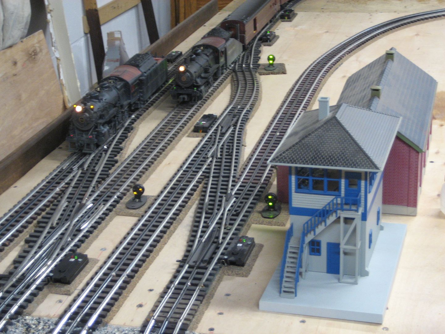
I would recommend powering the signals from the accessory terminal of the transformer. Then, use the outside rail to connect the common and light them when a train occupies the trigger section.
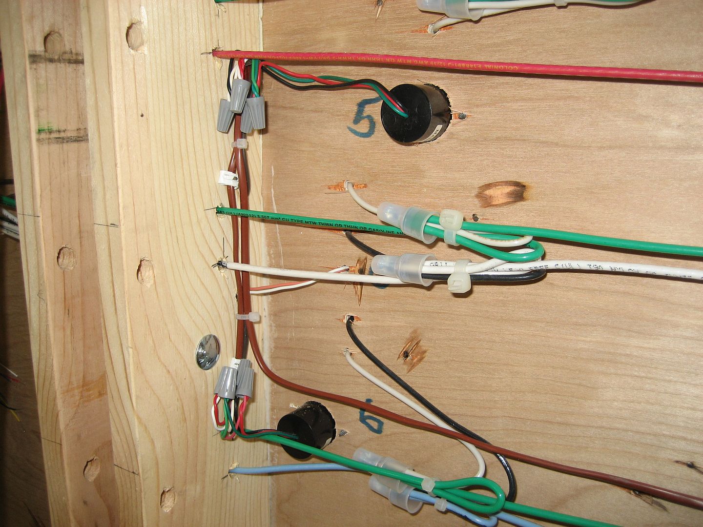
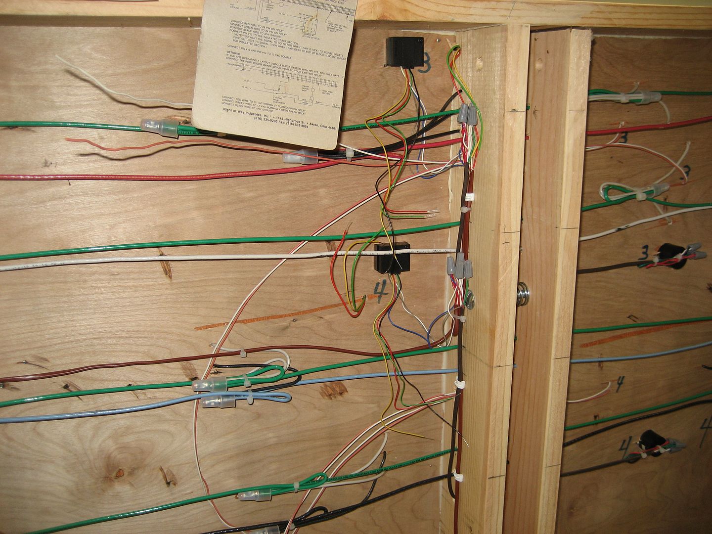
Some automotive stores carry .110 female quick disconnect terminals (crimp) that fit the FasTrack tabs underneath. If not one near you, you can find them on eBay. Soldering is the other option.