Since I'm nearing the end phase of my scratch build of the old Cambridge train station (see below),


I'm in search of some advice on my next project -- specifically, my plan is to model the nearby Cambridge Creek bridge:


What I need is a lead on both a source for an appropriate slow speed geared low voltage DC motor (or perhaps two, one for each side, if that's easier to arrange than transferring lift power between the sides), and the bits and pieces to control it (or them).

For control, I'm envisioning a DPDT center-off momentary toggle, wired to reverse the feed polarity depending on which direction the toggle is pushed, and two limit-of-travel normally closed contact switches, one for raised and one for closed (or four, if two motors are used), wired in series with one of the power feeds and positioned to activate when the bridge is in either fully closed or fully open position. The NC contacts of each of the pair of switches would be bridged by diodes (in opposite polarity), so depending on the polarity of the feed (as determined by the DPDT toggle), only one contact switch will be able to interrupt the motor at any given time.

I'm also open to ideas on how to construct the bridge section pivots, and how best to connect the motor(s). Ideally, I'd love to find that there's a pre-built mechanism I can adapt for this project, or something I can kit-bash into a reasonable facsimile. Any suggestions or leads greatly appreciated, and thanks!  8-)

Original Post

Replies sorted oldest to newest

@Avanti posted:

These days, I always go with linear actuators for that kind of thing. They are available in all sizes and speeds. They are often much easier to work with than traditional screw shafts. Try Amazon.

Thanks, Pete! As I mentioned to Bob, I already sent off for some N20 motors and gear from overseas, but I'll check into the linear actuators if I'm not happy with the geared-down motors.

@AlanRail posted:

these look like bascule bridges.

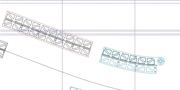
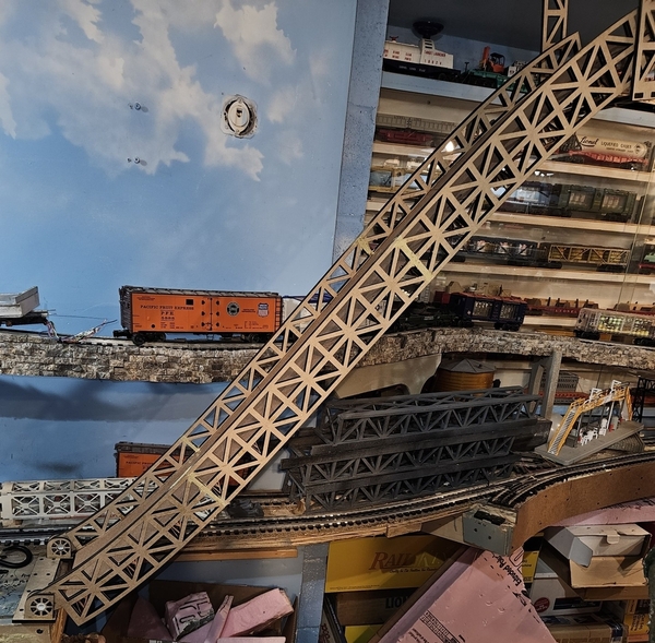
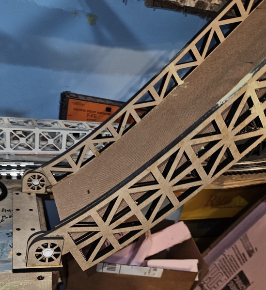
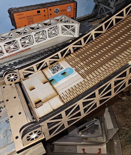
I'd laser cut the bridges with end pivots like this'bridge3


this is my curved bridge side truss yours would not have the entry curve to it.

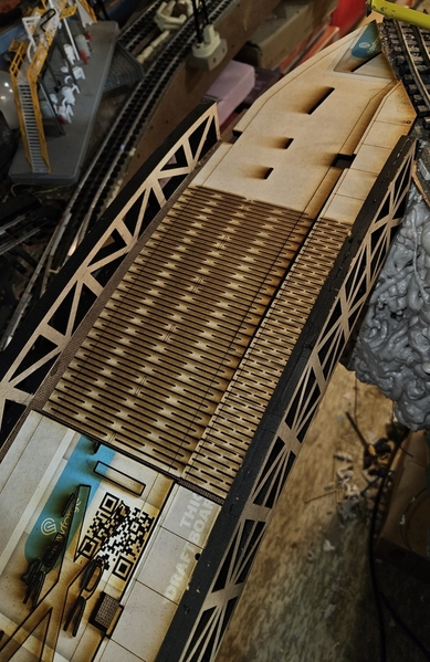
the highway and sidewalk would be laser cut as well to fit the side trusses

Dunno the technical name for the type of bridge, and I have not yet taken detailed photos of the bridge structure, but from the distance shot I posted above it appears the exposed side structure is only the pedestrian side rail, with the true support positioned underneath and closer to the center than the sides. I'll keep your product in mind as I investigate further -- do you offer a version that's half the width, since that seems closer to the depth of the under-deck supports?

@AlanRail posted:

Thanks for the link, Alan! From the article, I now know I'm attempting to model a fixed trunnion bascule bridge, in appearance and function much like the Charles J. Berry Bridge shown in the article, or the moveable parts of the venerable and iconic Tower Bridge over the Thames . . . well, sans the towers!

From the info I've been able to glean so far, the N20 motors I've ordered should have plenty of torque and power to rotate the leaves, and I think I can add enough counterweight in the under-deck section to make it all work. When I get some good pics of the prototype's deck and counterweight structure, I may get back to you to see if you can fabricate the needed bits. In the meantime, again, thanks for the info!

Add Reply

Post

OGR Publishing, Inc., 1310 Eastside Centre Ct, Suite 6, Mountain Home, AR 72653
800-980-OGRR (6477)
www.ogaugerr.com

×
×
×
×
Link copied to your clipboard.
×
×