Hi,
We are building a 6’ x 36’ layout using Fastrack. We are powering it with four 180 W Lionel Powerhouses connected through a TIU, using all four channels. We have set the two Variable Channels to Fixed since we will not be running any conventional engines. We have prewired for LCS, but have not yet turned it on because all six of the Sensor Tracks are not installed and wired to make all of the connections with the PDI cables. We also have MTH Wifi that we plan to use, but so far it is not connected to the TIU.
We have prewired as recommended for DCS – home run wiring, not bus wiring. There are four power districts. Each loop is divided into three power districts geographically. Each end of the outer loops are a district (Districts 1 and 3) and the centers of the loop are one (District 2). The yards are a separate district (District 4) that will be controlled with a BPC2 to turn the yards off and on.
The wiring for the loops comes from Fixed 1, Fixed 2, and one of the Variable Channels that go out to MTH Junction Boxes with 14G wire and then on out to the power feeds with 16G Wire. The Legacy Base (running version1.6) and all commons (both track and accessory power (from a Z4000) are connected at a Junction Box between the TIU and the track. All transformers, both for track power and accessories are phased correctly. When a Lionel Train that is controlled by the Cab2 goes from one power district to the other everything works correctly.
We started by laying out the two outer loops. As we put the pieces together, we are putting in the Lionel Command Control O72 switches (8 of them). There will also be 10+ O48 switches in the pull-through yards in the center of the loops that come off two reversing loops that are part of the inner loop, one on each end.
So far, we have hooked up about 2/3 of the outer loop. The power for the sections we have hooked up so far are powered by Fixed 1 and Fixed 2 of the TIU. Our problem is the Fastrack Command Control Switches. They are working very erratically. The O72 switches are being used as crossovers between the two outer loops, so two switches with the diverging legs connected form the crossover. They are powered by track power. Because of the power districts some of the switches do have insulated pieces that break the center rail either right before or right after the switch and sometimes between the two crossover switches. Sometimes, the switch works, and sometimes it does not. We have a couple of them, that even switch on their own (these switches are connected to an STM2 that is not yet powered or connected to the other LCS components).
By the way, four of the switches are the old number of product that begins with a 6-1xxx and some are the newer ones that begin with a 6-8xxx. There are four of each. At this point, we have moved them around so much, we do not know which ones are the newer and which are the older ones. Also, the behavior has become so erratic, it is not even the same switch that does not work every time, but there are a couple that always work and a couple that almost never work.
I do not know if it has to do with the loops not being completed and all three legs of the switch being connected to the track?
We have tried taking the TIU out of the equation, no change. We have tried positioning the switches in different locations with limited, but not lasting, success. Sometimes it seems to help to get closer to a particular switch with the Cab 2, but not always. It seems once you get a switch to activate it will usually continue to respond for a time. The Legacy Base is located near the center of the 36’ table. It sits below the tabletop. We have tried setting it up on top of the table, but that did not seem to help either. We have also now plugged it directly into the wall outlet rather than the surge protector. That seemed to help a bit so far, but the switches are still switching on their own and various ones do not always work.
We also tried: There is an O72 attached directly to the mainline, a second O72 forming a crossover. Both were working. Then we added an O48 at the end of the second O72, now 3 switches in line. The second O72 stopped working but the O48 worked. If we remove the O48 the second O72 begins working again. The first O72 never stops working.
We can pull one switch at a time from the table and take it to a test layout with a similar power set up, and they work correctly.
Any help would be appreciated,
Hubert and Marti
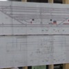
Layout map attached above. If you can zoom in, red x’s are insulated track (center rail only). P#-xx are power leads showing the three power districts on the main loops. So far we have both sets of switches at the top of the map and the set on the lower right connected in the outside loop only. The other section of that loop is not yet completed. The two switches that change on their own randomly are the two on the right end of the outside loop.


