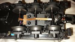
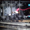
About a month ago, I posted a questions about my MTH 2-8-0 (20-3562-1) pausing or stalling on switches and was advised that an additional wire could be ran from tender wiper to frame ground to help prevent stalling on insulated sections of track. Could someone please explain how this will work to improve ground on insulated track sections. I may be interested in attempting this improvement, but would like to understand the process better. thanks speperak
Replies sorted oldest to newest
Tender does not have a pick up roller. It only has a axle wiper.
thanks speperak
Sperarak. You are correct. When going slowly over a non-derailing switch, one side of the drivers does not contact ground and the motor loses power. When going faster, the loco's intertia carries it past the spot. On the other side of the loco, you have an insulated wheel via a traction tire. (On the Rail-King 2-10-0, the rear axle has the wheels insulated from each other; don't know about the 2-8-0) Under certain conditions of trackwork, the loco can rock slightly so that none of the drivers on the side away from the non-derailing rail are making contact. The cure is to run a wire from the tender axle wiper to the tender frame. The drawbar has a ground conductor, so the loco keeps getting power.
I discovered this when the R-K Decapod was first delivered and I encountered this stalling problem. Shortly thereafter, a friend had the same thing happen. The wire cured the issue for both of us.
BTDr is addressing a different issue.
I suppose you could also reverse a couple of wheel sets but that would mean taking the trucks apart..... Nah! It would be a permanent 3 rail engine until reversed back.
MTH usually has a wiper on a trailing truck, but when there's no trailing truck....... Unsaid is why not put a wiper on the pilot truck.
RJR, I was thinking that the drawbar must have a ground to the tender frame. It seems that only three tender wheels on left side actually connect to wiper. When these three wheels cross insulated section of track the engine stalls. I have checked it, and the three wheels are located directly over the insulated section when stalled. I have two questions. 1. where is the tender frame picking up ground? From the engine wheels? and 2. connecting to the tender frame seems easy enough, but how did you connect wire to wiper?
Gregg, I too had wondered about reversing a set of the insulated wheels to connect the right side rail to the wiper. I would like to see a pic of how wires should be soldered to tender wiper.
I don't know if your loco is 2-rail and if that makes a difference; I'm not familiar with Premier 2-rail setup, so I'd best defer to those who are.
In the R-K, the drawbar connects the loco and tender frames, in that at each end the drawbar somehow connects with each. My problem was that the R-K Decapod tender as it came from the factory, had no wire between wiper and frame. The tender wheels and axles are conductive across the outer. rails I soldered a fine wire to the wiper and crimped a spade terminal on the other end, which I slipped under a screw head that was under the frame.
If your tender has two 3-axle trucks, can you get ground pickup from the other truck as well?
The problem to which Robert is alluding is caused by the screw that secures the wiper to the tender frame being over-blackened, causing it to lose conductivity to the tender frame. Jumpering from that screw with a wire tucked under the screw head right against the wiper, to under a a screw on the tender body, will restore the lost outside rail conductivity.
The wireless drawbar already has a Common connection between the engine and the tender.
MTH is aware off this issue and has implemented steps going forward to eliminate the problem in the manufacturing process.
For a 2R - 3R steam engine the switch on the tender should connect both left and right tender wheels to become the outside ground going to the PS-2 or 3 board. If this is mis-wired or defective switch you may not be getting this connection.
On the engine side, their is no switch to connect the outer wheels. Chassis ground (left engine wheels) does come over via the drawbar ground wire spring for PS-3.
The right wheel and center rail pickup actually come across the 6 pin drawbar wires.
When the switch is placed in 3 rail, the engine right side wheels are routed to ground input to PS-3 board. The center rail pickup is routed to center rail input to PS-3 board.
So the left side engine wheels are left to make connection to ground via the drawbar wire spring to the tender draw bar post/chassis. G
Thanks George. I suppose it's a great engineering feat but... Is it a good 3 rail engine?, 2 rail engine ? Apparently not by reading this thread. I wondered what that spring wire was.
Maybe place the engine on a nice soft towel upside down and have a go with a continuity meter to see what's common to each other. One side of tender wheels to other side of tender wheels. ETC . (pS check with wife before using good towel)![]()
(pS check with wife before using good towel)![]()
There are some very wise persons on this forum.
If I recall correctly, on the RK Decapod at least, Common runs through an actual trace on the drawbar.
Barry Broskowitz posted:If I recall correctly, on the RK Decapod at least, Common runs through an actual trace on the drawbar.
Barry, That would be correct for a 3R only. If a 2R-3R like the original posters engine, only the right wheels and center rail pickup go through the 6 pin drawbar for PS-3.
Frankly from an engineering and simplicity they could have stuck with a 10 pin drawbar and had a line for the left wheels. G
Electrical pickup on MTH 2/3 rail steam locomotives is sub par and needs to be redesigned for reliable 2 rail operation. My new N&W J randomly stalls due to poor pickup in areas of the railroad no other locomotives have issues. Even on straight track!
As already pointed out one component of the issue is wiring fastened with screws coated with a non conducting finish. The J's left rail locomotive/ frame pickup is done with 3 sprung plungers bearing on driver axles and wired with coated screws. My fix was to file the finish off the underside of the screw head and the end of the screw which comes into contact with the plunger spring. Right rail pickup is done with pickup on only 2 wheels of one 6 wheel tender truck and 2 wheels on the trailing truck. The design does not bring into play some form of pickup on all the locomotive and tender axels. Someday I need to add additional pickups.
Ed Rappe
RJR - Thanks for the pic. That screw definitely would simplify running the wire. The axle wiper on my engine is mounted with two tiny copper screws and is insulated from frame with thin plastic. Any ideas on attaching a wire? There is already a wire attached to wiper that enters tender and joins bundle.
Attachments
Perhaps add another wire from the bundle and attach to tender floor just like RJR did, only this time from the top. There must be a screw handy that you could slip the connector under.
Not wanting to hijack this thread, but I have a 20-20248-1
SP Gp9 with a similar issue and it's driving me crazy.
Is it possible to ground both sides of the axles to eliminate
this problem and make it 3 rail only?
speparak: If there's already a wire on the wiper, I'd remove the tender shell and see where it goes.
Zephyr 1 posted:Not wanting to hijack this thread, but I have a 20-20248-1
SP Gp9 with a similar issue and it's driving me crazy.
Is it possible to ground both sides of the axles to eliminate
this problem and make it 3 rail only?
There has to be a way. Doesn't the 2/3 rail switch put both outside rail pick-ups together when set to 3 rail? Flip her over on the work bench and test with continuity meter.
Gregg,
I've checked continuity, and it seems to be intermittently good and bad.
With traction tires on 4 of 8 wheels, it looses ground when going over
Gargrave back to back turnouts. The rest of my locos don't have this issue.
Any other thoughts or ideas on solving this grounding problem?
Thanks
For a diesel the switch should connect the wheels. Open it up, change black screws for nickel, check wiring from break, make sure axle contact springs in place, remove switch and go to direct wiring. G


