I bought this in 2018 with no directions.  Somehow that year I figured out how to wire it up to my Christmas layout.  I didn't write down how I did it though.  I remember getting some advice on how to wire it from the person that I brought it from.

I want to use it again this year but can't figure out the wiring.  For some reason I think I used an AC relay somehow too.  I bought the track activation device but found a way to use an insulated track instead.  Looking at the only picture that I have of that layout I also noticed using a separate small N or HO trannie but don't know why (it has an AC option so maybe I used it to power the relay????).

Can someone explain the wiring for me?

As always, thanks very much - Walt

PICT0069

PICT0070

PICT0071

Attachments

Images (3)
  • PICT0069
  • PICT0070
  • PICT0071
Original Post

Replies sorted oldest to newest

Thanks Rob.  Patience !!!!  Are the red and green circles posts on the stand? 

I'm also confused about completing the circuit.  I can see when a piece (engine, car) is on the insulated track that the circuit gets completed.  That should make the light turn red.  BUT when there's nothing on that track the circuit isn't completed.  Someone I had the green light come on when nothing is on it.

sorry about my limited electrical knowledge.  I'm trying to learn.

walt

Btw: here's the only picture that I can find of it and it's too small to really see well:

zz - Overall from front door day retake

Attachments

Images (1)
  • zz - Overall from front door day retake

I was editing my first reply when you replied.  To use a SPDT relay with insulated rail track, the insulated rail (when the train runs through) would provide ground to energize the relay coil.  The relay contacts would also provide ground to either the red or green bulbs via two of the terminals on the Signal stand.

Relay connections:

Coil terminal 1: DC +

Coil terminal 2: DC Ground (from insulated rail)

Center contact: Track Ground/common

NC Contact: To 153 Signal Green Bulb ground terminal

NO contact: To 153 Signal Red Bulb Ground terminal


153 Signal Center terminal: AC power

Last edited by SteveH

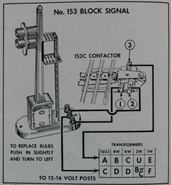
First, lets us look get some electrical basics down. A light bulb has two terminals, one for hot, one for return/common/ground.

Now, lets look at your signal. It has two light bulbs, so one may expect 4 terminals, two for each bulb. However, in this case, one wire can be shared with both light bulbs, giving us three terminals. The center terminal is shared between the bulbs, and then the outer terminals connect each to one bulb.

For testing purposes, you can take ~14VAC from your power source and connect cone wire to the center post, and then touch the other wire to an outside post. By touching an outside post, you should get one light to illuminate. Touching the other outside post should cause the other light to illuminate.

Now we have the basics down and we can get a little more advanced.

153C Contactor

Included is a 153C contactor. Terminal 3 on the 153C now gets connected to the wire you used to touch the outside terminal for testing. Terminals 1 ans 2 go to the outside terminal of the signal. Terminal 1 is Normally Closed and generally should be connected to the green bulb. Terminal 2 is Normally Open, when weight presses down on the 153C, it becomes closed (and terminal 1 becomes open) changing illuminated light to the red one.

The thumb adjustment screw changes the weight sensitivity of the 153C contactor.

Relays

Now, it can be hard to tune the 153C to get the desired operation, so relays of all kinds have been used. Instead of weight triggering the change between lights, a solenoid is used. So you still have 3 terminals as before, a "switched common", "normally open", and "normally closed". But now you add two terminals for the solenoid, "activation hot" and "activation return/common/ground".

Now to trigger the solenoid...

Relay & Insulated Track

Take the activation hot of your relay and connect it to your center rail or accessory buss (with common ground wiring scheme). Take the activation return/common/ground and connect it to the insulated activation rail. The metal wheels and axles will conduct complete the circuit between the outside rail and the outside insulated activation rail, trigger the relay to switch on its solenoid and change the illumination state of the signal.

Now, there are many products that have the relay functionality built in that I can recommend, but possibilities are endless. It sounds like you may also have a relay you can already use:


O22

Now, if you have an O22 switch, you can directly hook the signal's three terminals directly up to the three terminals on the O22 switch (along with the O22C controller) and control the light state based on switch direction. The O22 is essentially acting as a latching relay.


I hope that this all points you in a direction and get you on your way. It is quite a bit to take in, especially if one is not electrically inclined, so don't hesitate to ask clarifying questions.


Edit: There was no activity on this topic when I started compiling my response, and then once I completed and proof read it for submission, I guess a lot happened!

Attachments

Images (1)
  • mceclip0
Last edited by bmoran4
@walt rapp posted:

thanks steve.  my relay is an AC relay but I would think just substituting AC for DC in your directions would be the right thing to do ???????

I'm sorry but I am just not up to snuff when it comes to relay wiring and operation.

Correct,  if your relay coil is activated by AC, then yes you can make that DC to AC substitution.

No apology needed, we all have our strengths and our learning opportunities.  It's better to ask questions, than to make incorrect assumptions.

I putzed around for a good 3 or 4 hours this weekend while studying the diagrams and verbiage here.  I don't care to comment on my thoughts though.  I was  wrong earlier when I stated it was an AC relay.  It's DC.  Sorry about that one.

Possibly to help others who, like me, are not familiar with relays and an electrical device that has 2 options (red and green lights) I drew up how I wired it to get it to work.  To me, I show a few connections that are not in the diagrams.  But maybe I didn't read them correctly.  All that I know is what I show here got things to work.

I want to repeat my appreciation for those that jumped in on this thread to help out.

- walt

Here's the way that I wired things:

the way i made it work

Attachments

Images (1)
  • the way i made it work
@walt rapp posted:

I putzed around for a good 3 or 4 hours this weekend while studying the diagrams and verbiage here.  I don't care to comment on my thoughts though.  I was  wrong earlier when I stated it was an AC relay.  It's DC.  Sorry about that one.

Possibly to help others who, like me, are not familiar with relays and an electrical device that has 2 options (red and green lights) I drew up how I wired it to get it to work.  To me, I show a few connections that are not in the diagrams.  But maybe I didn't read them correctly.  All that I know is what I show here got things to work.

I want to repeat my appreciation for those that jumped in on this thread to help out.

- walt

Here's the way that I wired things:

the way i made it work

Walt, I'm glad you got it all working.  Your way shows one of two possibilities.  Since the incandescent bulbs in the signal tower have no polarity, the connections could also work with the signal tower center post connected to hot/center rail and the two outer posts getting the switched ground from the relay via the uninstalled outside rail as shown in the original directions using the 153 Contactor.  Both ways are fine since the signal tower's 3 connections are all insulated from it's frame.

thanks again Steve.  So if I read you correctly here's what I think you said:  I could take the center post on the light stand and connect it to the center rail instead of the ground rail and then take the wire on the relay (that I show connected to the blue relay post) and move it so that it connects to a non-insulated ground rail instead of the center rail.  If that's correct then it's nice having 2 options in case in the future your suggestion makes it easier to wire.

- walt

Last edited by walt rapp
@walt rapp posted:
I drew up how I wired it to get it to work.  To me, I show a few connections that are not in the diagrams.

You got it right. The one diagram assumed you were using common ground and should look like this:

AC%20relay%20diagramA

Your use of DC is correct, as well. You could even use a car battery if needed. An alternative when using DC relays is to use the AC trigger rail as in the above diagram, but have the relay solenoid powered through a full wave bridge rectifier.

Attachments

Images (2)
  • AC%20relay%20diagram2
  • AC%20relay%20diagramA
@walt rapp posted:

thanks again Steve.  So if I read you correctly here's what I think you said:  I could take the center post on the light stand and connect it to the center rail instead of the ground rail and then take the wire on the relay (that I show connected to the blue relay post) and move it so that it connects to a non-insulated ground rail instead of the center rail.  If that's correct then it's nice having 2 options in case in the future your suggestion makes it easier to wire.

- walt

Yep, I think you got it.  It could look something like this:

the%20way%20i%20made%20it%20workmu

Attachments

Images (1)
  • the%20way%20i%20made%20it%20workmu

Add Reply

Post

OGR Publishing, Inc., 1310 Eastside Centre Ct, Suite 6, Mountain Home, AR 72653
800-980-OGRR (6477)
www.ogaugerr.com

×
×
×
×
Link copied to your clipboard.
×
×