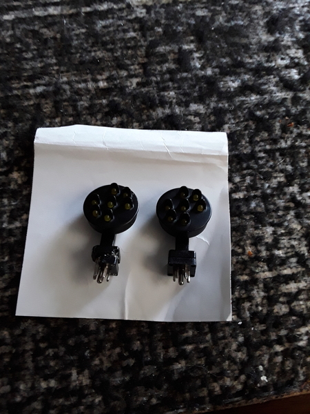
I purchased the subject signal yesterday at a train show 20190121_153951and I goofed up two signals by burning out at least one bulb in each. Also, when I wire it into my Lionel 153 IR I can only get the the middle light to work on my two good signals as it came with four. Can you please advise if I can fix the two signals with the burnt-out lights and where to get the LEDs. Also, can you tell me how to check the LEDs to see which ones are good. I also need help in how to wire this thing. My other MTH signals work fine the way I wire them into the Lionel 153ir but this one doesn't. Again, I just get the Middle Light to work? As usual, I need your help.
Thanks again, Jerry


Attachments

Images (1)
  • 20190121_153951
Original Post

Replies sorted oldest to newest

Like a dummy I was goofing around with the loose heads an applied current to the plugs and I believe I shorted out the bulbs. When I plug in my two good signals they work, that is the center bulb lights up. The ones I goofed up also smell and there was a little bit of smoke. Both heads that work we're plugged into the bridge itself and into the Lionel 153ir via the three wires that came out of the bridge bottom. Do you have any idea where I could get Maybe my two repaired? I still can't figure out why it won't work

You mean you applied AC Accessory voltage directly to the signal head 4-pin?  That would in all likelihood blow up the internal LEDs.  In which case you'd have to see if MTH sells replacement signal heads (which you'd think they would since apparently the stock bridge has locations for 4 heads but only supplies 2).  If attempting to repair a head, I'd think it comes down to whether you can peel/pry/pop open the head to expose the LEDs.  Since LEDs should last a lifetime, I can't imagine it was designed to allow easy replacement of individual LEDs.  But if you can open it up and take a photo, I'd think the actual LED type would be easy to find for a nickel a piece or so.

As to working with what you think are the known-good heads.  What I'd do is test it without the 153IR.  As the instructions say, apply AC common to Black.  Then apply AC power to Green.  The signal head plugged into the corresponding bridge socket will turn diagonal, then vertical after a few seconds.  Then remove the AC power to Green and apply AC power to Red.  The Horizontal aspect should come on until you remove AC power from Red.  If you can't get this behavior then it won't get any better using the 153IR!


You can purchase the MTH signal heads for the 11030 signal bridge, separately and avoid the hassle and labor of trying to disassemble a head to change out LEDS/   

It's MTH part # 30-11030a.

If you're patient, I have seen 2 packs sell on ebay for between $15 and $20.00, or you can try contacting some of the larger dealers/OGR sponsors to see if they have them in stock. 


I haven’t had the need to take one of these heads apart but, I believe there is more to it than just some LED’s.  When activated the clear signal change to stop when the power is removed from stop the signal changes to restricted and has a timer before changing to clear.  That logic circuit is in the head and, probably part of the same circuit board.  You probably smoked more than an LED or two.  I think Chris has the right idea, check eBay as well as some of the forum sponsors.

Danr posted:

I haven’t had the need to take one of these heads apart but, I believe there is more to it than just some LED’s.  When activated the clear signal change to stop when the power is removed from stop the signal changes to restricted and has a timer before changing to clear.  That logic circuit is in the head and, probably part of the same circuit board.  You probably smoked more than an LED or two.  I think Chris has the right idea, check eBay as well as some of the forum sponsors.

I don't have one to look at, so if the head has more than LEDs then I stand corrected.  I was using the following where someone is selling the signal head, socket for signal head, and a separate control board which suggests the logic circuit (e.g., diagonal to vertical delay timing) is on a separate board and not inside the signal head ... but I must be mis-interpreting.

Untitled

In any case, if your signal heads are write-offs, before you toss them would you be willing to pry one open and post photos of what they look like?

BTW in above photo the signal heads are $5 if that's a good price?  I don't know about shipping.

http://www.customsignals.com/close-out-items.php

Attachments

Images (1)
  • Untitled

As I said, Stan, I haven’t taken this signal apart.  The signal bridge can support 4 heads which are all triggered independently.  I haven’t taken the bridge apart, either.  Based on the picture you found, it looks like Jerry may have only cooked the lights in the head.  I would also be interested what is inside the head, for future reference.

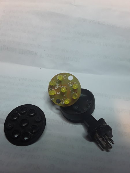
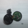
It turns out that you do not have to destroy it to get it apart but you do need some small tools.  Below are 3 pictures I took of the head.  As Jerry discovered you need a 1mm Phillips screwdriver but you can do it with a1mm flat blade. You only need to remove the 2 screws on the case to remove the front cover.  To do any further work you will need to remove the 2 screws on the mast.  Once inside, you can see that you have 7, 3mm, yellow LED's.  On the back of the circuit board you have what looks like a diode and a zener diode (someone more familiar can tell us what they really are.

Jerry, it is difficult to tell from the pictures but I would think this can easily be repaired by someone with the right tools and knowledge.


Attachments

Images (3)
  • IMG_0486
  • IMG_0487
  • IMG_0488

Thanks guys for posting the pictures. 

Yes, if you directly applied Accessory AC voltage to the pins of the signal head you probably destroyed two or more LEDs.  So as Dan says, those look to be 3mm Yellow LEDs which can be had for a penny a piece on eBay (free shipping from Asia).

3mm leds for a penny each

Whether it's worth your time is another matter as it will require some soldering finesse!

Anyway, one takeaway (for me anyway) is the signal head has separate circuits for LED vertical-diagonal-horizontal aspects and hence is not slaved to the timed diagonal-to-vertical delay used in the MTH signal head.  Of course this would mean using something other than the stock controller board (which apparently resides in the base of each side of the structure).  From earlier photo it appears that each controller board drives two signal heads.

Attachments

Images (1)
  • 3mm leds for a penny each

Add Reply

Post

OGR Publishing, Inc., 1310 Eastside Centre Ct, Suite 6, Mountain Home, AR 72653
800-980-OGRR (6477)
www.ogaugerr.com

×
×
×
×
Link copied to your clipboard.
×
×