Hi,
My name is Jarrod, I am new to the forum but I have something that I wanted to get some feed back on. As you know if you have a MTH Operating Accessory its kinda of a pain to wire up, you have to run up to 5 wires. Well I have developed a way to make that process simple.
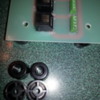
Here is what I have come up with. I designed a board to consolidate all the wires to a CAT6 23awg cable. The board is designed to be a terminal strip for power with one set of binder posts for AC power, a phoenix connector on one side of the board to connect the 2 wires you need to connect to the AIU and on the other side a RJ45 Jack. The board consolidates all the wiring into the RJ45 Jack. You then  take your CAT6 23awg and put a RJ45 Plug on it with the correct wiring scheme. You connect the 45 Plug into the Jack on the board and run your Cat6 cable to your Accessory were you can connect the wires to the accessory. using the blue pair on terminal A, orange pair on terminal B, green pair to terminal C, white brown to Terminal D and brown to terminal E. This puts all your wires in on sheath and creates a unified cabling solution. I know there are going to be questions, I am open to any you may have. I have this Patented and I am looking for feed back or even some people to try the unit out. I call it the EIU Electronic Interface Unit. If all goes well I can sell this unit for $50, once I get feed back, I think this would be great for modular layouts.
Thanks,
Jarrod

Attachments

Images (2)
  • IMG_1799: EIU
  • 20140423_212950
Last edited by NS1719
Original Post

Replies sorted oldest to newest

I like the idea! For those like me that are not well versed in electronics, a few more pictures would really help. I'd like to see the complete set up including the cable going to an accessory ( in fact have several lined up and wired. Also, illustrate connecting the jacks to the cable and matching the color coded wires to the accessories.

I think you would get a lot of customers if we had more details. As Penn-Pacific said above, pictures!!

Thanks everyone for taking the time to look at my design.  I will post a video of how it works with the accessory as you have asked.  Although it will be later today as I'm in training with NS,  so please check back around 5. I hate being on camera so sorry if I look like a deer in the head light. Haha

Not sure if you're showing just a prototype version but I suggest adding mounting holes in all 4 corners...and perhaps some in the middle of the board if there's board flex when attaching wires or cables - looks like standard 1/16" board which will flex given it's as long as an AIU.  Your installed photo shows mounting screws but the board-only photo suggests the user would have to drill or enlarge holes.


Separately, there have been a few threads where multiple AIUs over long distances experience a voltage drop so the furthest AIU can intermittently operate.  One solution suggested by an OGR contributor is to supply a separate 12VDC supply that plugs into the RJ of the last AIU.  It comes up infrequently so I'm not sure how many you could sell but since you're working with RJ connectors and such, it would make for a nice plug-and-play accessory.


Also, was this just a one-off project you did for yourself and are kindly offering to the OGR community?  I think Operating Accessories don't get the attention they deserve so if you're interested in developing additional products along the lines of what you've done I believe you'll find interest.


Last edited by stan2004
Stan2004,
Tjanks for pointing those issues out.  The picture is of the proto type.  I just recently received the new models which were upgraded.  The board is twice as thick,  Has 4 holes one in each corner and the board will be supplied with feet like Mth uses on their terminal strip.  The new board is wider due to the added hole and feet. So all you would have to due is mount the board and make your 2 connections to the AIU. 
Thanks for your input. 


Sent from my Verizon Wireless 4G LTE Smartphone

-------- Original message --------
From: O Gauge Railroading On Line Forum
Date:07/16/2014 1:33 PM (GMT-05:00)
To: NS1719
Subject: Reply By stan2004: MTH Operating Accessories!

Stan2004,

Sorry I only saw the one post about the boards thickness and holes for mounting. I will look into the campanion board concept. That is a good idea, for voltage will drop over a long run of Cat6. I will do some testing and see what lengths I come up with, to see where the voltage drop becomes a problem. I know most modelers today are switching to LED Lights, I have not checked to see if you can get those in AC, I am sure they are out there though. I believe MTH operating accessories are all ran off of AC. Unfortunately MTH does not give much information out on their electronics, they don't even say what size wire to use or amperage the accessory requires. I have a pretty good idea what it will take to keep the voltage and amperage in the green just from testing with the VOM. The companion board is a good idea though! 

Also I agree 100% Operating Accessories do not get the attention they deserve, I know wiring can be complicated, especially on large layouts and my goal is to help eliminate that headache.

Again thanks to all for your input and interest please keep the feed back coming...

I will be uploading the video now and should be up by 4:30.

Thanks!

Just to be clear, the AIU voltage drop issue I'm referring to is discussed in the following thread with a proposed solution by Marty Fitzhenry:


https://ogrforum.ogaugerr.com/t...by-backfeeding-aiu-5


The "problem" is the voltage drop from TIU to AIU to AIU to AIU.  So the 12V that powers each AIU drops a bit on each cable run as it daisy-chains through multiple AIUs.  So that on the far AIUs the 12V drops low enough that the AIU does not operate properly.  Marty suggests adding a 12V supply (about $2 on eBay) at the far-end as shown below.  It needs an RJ connector and plugs into the last TIU in the daisy-chain.  Again, I have no idea how many of these you could sell but if the objective is to be the go-to-guy for simplifying/improving AIU wiring to accessories, this IS a "known" problem which continually pops up on the forum.


ogr AIU 12V cable drop

I think you are thinking of the voltage drop from the EIU to the accessory if there is a long CAT6 cable run and a large current draw by the accessory.  That may be a problem in some instances but I'm just going by what I've read about on the OGR forum in terms of AIU wiring/hookup issues.


And yet another idea that popped into my head was to provide the instructions for a user to hook-in a manual pushbutton switch to operate/activate an accessory.  Again, I go by the "problems" I read about here.  So if this is a large layout perhaps at a club on open-house day you might want the kids to be able to activate an accessory but you don't want them messing with the DCS remote.  In such a case you'd want to wire a manual pushbutton switch of the like.  It may seem obvious but how does this wire-in to your EIU?  And how would you install a timer or equivalent so that the accessory operates for 1 minute (or whatever) on each button press and then stops.  Just a thought...

Attachments

Images (1)
  • ogr AIU 12V cable drop

I have read the forum on the AIU problem and will attempt to design something that will work as you have pictured. I will have to do some research when I get home but I will find a solution that will be easy.


Also I understand you were talking about AIU to AIU.


As far as the EIU to the accessory, I would think for the most part its not going to be much more than 30ft away and my layout is set up that way. I will still see what distances I can get that Cat6 cable to go though for future references. 


Now for the manual push button, I have a solution for that. I do not have a picture available but its basically a RJ45 and a RJ11 Jack in a box. This could get confusing for most if you are not familiar with telecommunications, I plan on offering this solution with the EIU. I am also working on designing a push button that will have a RJ11 plug which in turn would plug into the RJ11 or Phone Jack.


The accessory would be wired with the appropriate length Cat6 and the end of that cable would have a RJ45 Plug one it which would plug into the RJ45 Jack in the box. Basically inside the box housing the RJ45 & RJ11, when terminating the RJ45 Jack you would cut all the pairs down except the 2 wires that go to the AIU relay, they would be punched with out being cut and looped to the RJ11 Jack where your can plug in a Push button with a RJ11 Plug. 

I know it may sound confusing but I will get a display together and show you how I plan to do this. The system works, I have it in operating order on my layout.


I hope this helps, If you need me to explain more I can. FYI I was a communications technician for 11 years and don't expect anyone to understand if your not familiar with communications of Cat6. But pictures do say a thousand words and I will get those to you ASAP.

Stan2004,

I understand where you are coming from. I was just looking to apply this application to MTH Operating Accessories, but after your input, I can understand applying this to the DC side. I would like to see the EIU be able to be used for any accessory out there, either a MTH Accessory to a lighted building. I may need to do alittle more research on the DC side with the AIU, and the timer. As for the Mel's dinner it should only activate and play the scene until that scene is over and wait for another activation to return the accessory to its original state. The only way it should keep going on and on is if you select that in the options on the remote, unless there is something I am missing. I will do what ever it takes to bring the operating accessories to light and help simplify wiring them. All your input has been great and would like to hear more as it comes to you. As you have said the accessories have been left behind and they are as much of the layout as anything else. 


rtr12 If you have ideas that you would like to see done I am open to them, unless you want to try them out on your own on the board. I will get in touch with you soon. I am looking to get 100 orders hopefully, which helps keep the cost down on the boards. If  I find 100 people interested the boards will only cost $42 plus shipping.


Again thanks for you feedback I hope the video was somewhat informative other than me looking like a deer in the head lights. lol

Was thinking about using my Atlas-O switches, lighting etc. with them in addition to accessories. Would make for some nice neat wiring with those also. Some (maybe all?) of my switches will be using the Atlas 6924 boards. The cat5/6 wire probably would not be suitable for some of the 6924's wiring, using the pairs might help though? For the switching functions I think it would be fine. Need to get my wiring plan together and then look at your boards again. I think I could probably use at least 3 so far, still thinking about other uses.


As I said earlier, I like Stan2004's ideas also. He is way ahead of me in the electrical/electronic departments though, as most of the other folks around here are as well. Sometimes it takes me a while to figure out what they are all talking about. 

rtr12,

I understand what you are looking to do and it is possible with this board. Now one thing to note my board is only a consolidation point, you still have to use the AIU or a Lionel module. 

The EIU will work with both MTH/Lionel Operating Accessories. The only difference is the wiring at the accessory. MTH Accessories will use all 4 pair, where Lionel will only use 2 pair. The reason for this is, that mth has their timing module built into the accessory where Lionel's Accessories are in the module you mount under the table.

Again both manufacturers accessories can still have the activation button in line with this board as described above. When I go to sell these I will provide the correct wiring schemes for the RJ45/RJ11 Jack and Plug. This way you can do alot of the work at your pace and save alittle money. I will also have the cables for sale if you are unsure of how to do that practice. 


*****On another note Lionel has made contact with the company I have been working with on the patents and is interested in EIU so we will see what happens there. Although usually if someone buys the patent they usually only allow it to be used for their application. Depending one what they say, I may keep it to myself so everyone can use it in their own way.******


Feed back about Lionel looking at the EIU would be appreciated and your thoughts.

Thanks

Jarrod

I understand about the consolidation point, that's a big part of the appeal of your board for me. I will probably use an AIU as I have a DCS and can't seem to get a Legacy system (had one ordered for almost a year). Anyway, Lionel requires way too many different items to do what 1 AIU will do. They are kind of over complicated in that area in my opinion. AIU's also have more I/O's in one item so you can cover a lot more stuff with one device. Also, your providing instructions for the various accessories is a big plus that will help a lot of folks.


Was also thinking about options other than AIU's or Lionel devices for inputting to your EIU. Why wouldn't a manual switch operator, relay, manual switch or something work just as well? From what I understand about the EIU it looks feasible.


Congratulations on Lionel's interest. I was going to suggest MTH might be interested in your boards as well as Lionel. MTH was my first thought because of the AIU mentioned and the terminal strips they already offer for track power.  Don't know, but I would think MTH would have some interest as well? Might be worth talking to MTH. If you decide to sell the patent it's possible they might both be interested and you could end up getting a better deal.


As for selling your patent to a larger manufacturer, personally I would like to see you keep it. A lot of headaches like manufacturing, marketing, website, shipping, support, user abuse, defective products, repairs etc. would be eliminated by selling. But if you could handle all that, I'm sure you would probably provide much better service to us as end users as you would have a bigger interest in the promotion and sale of the product.


If you don't make a deal with one of them, my fear for you would be that your idea will be copied and similar products could be produced anyway. However I have no idea how all this patent and getting things manufactured stuff works, so I don't know it that would happen. Or even if Lionel or MTH would do something like that to a small business that was just trying to help the hobby? A tough call either way (would be for me anyway) and which ever one you choose, I wish you much success.

Last edited by rtr12

Thanks for your feed back, my thoughts on the selling of the board are the same as yours. I would like to keep it private and be able to help keep progressing on accessories.

Although if they come with a good offer I will have to look at it. lol

I would like to see MTH get involved. I designed this primarily for their accessories. I am just lucky enough to have pretty much have designed it to accept just about anything.

I also agree that the AIU is a much better system. Lionel has way to many components in my opinion as well, you can have alot of money wrapped up in them compared to the DCS and AIU.

As far as the manual switch operator, relay, etc. I don't have that information, but I am sure the board can handle whatever you could come up with.

As for helping everyone out, I believe in a cost efficient product and being able to provide the information needed to make the cables and connections on your own. Again I am sure some are not familiar with making these connections and I would be happy provide them for a reasonable price.

In my opinion the customers feedback is the number one priority and by just making a board and stopping there is not the way to go.

I have seen on other forums about the customer service being horrible. If I do end up selling this board and others that I can design, there will always be room for improvement from you the customer.

Sorry if I was blabbering lol

Thanks everyone for your support and feedback. Still looking for more if ya have any. 

Thanks stan2004, and just to be sure, I would think you would want this to work with the AIU, ASC or as a stand alone unit. Of course all 3 would have the option for a push button? I am looking into it and I will come up with something that you are looking for. I just want to be sure I fully understand what you would want it to work with. 

Here is an update of the finalized prototype,  if you are interested in one they are 42 dollars plus shipping,  delivery will depend on amount ordered.  Also I am working on a way to incorporate the DC side of accessories with a timing relay that you can set at your own will.  This will take about a month to drawn up but it is I progress. Thanks again for your support.

Attachments

Images (3)
  • 20140726_201421
  • 20140726_201321
  • 20140726_201209

Hi Everyone,

I just wanted to update this forum and let you know that I am now selling the EIU boards at $42.75 each plus shipping and handling. I do except paypal. If you plan on using paypal the price with shipping will be $50.50 a board. Also Lionel seems to be very interested and are having a meeting this week about this product. So this item may be in their hands soon and with that being said I am sure it may be more than $50. I have a total of 50 boards available and with the first 25 orders, there will be 2, made up CAT 6 cords to desired length for each boad.


Also and another update, as discussed earlier in this forum, I am designing a timer board for 12vdc accessories as some members have inquired about, things are in the works so hopefully there will be some good news soon. Work in progress. lol

Thanks,

Jarrod

Originally Posted by NS1719:

       
Hi,
My name is Jarrod, I am new to the forum but I have something that I wanted to get some feed back on. As you know if you have a MTH Operating Accessory its kinda of a pain to wire up, you have to run up to 5 wires. Well I have developed a way to make that process simple.
Here is what I have come up with. I designed a board to consolidate all the wires to a CAT6 23awg cable. The board is designed to be a terminal strip for power with one set of binder posts for AC power, a phoenix connector on one side of the board to connect the 2 wires you need to connect to the AIU and on the other side a RJ45 Jack. The board consolidates all the wiring into the RJ45 Jack. You then  take your CAT6 23awg and put a RJ45 Plug on it with the correct wiring scheme. You connect the 45 Plug into the Jack on the board and run your Cat6 cable to your Accessory were you can connect the wires to the accessory. using the blue pair on terminal A, orange pair on terminal B, green pair to terminal C, white brown to Terminal D and brown to terminal E. This puts all your wires in on sheath and creates a unified cabling solution. I know there are going to be questions, I am open to any you may have. I have this Patented and I am looking for feed back or even some people to try the unit out. I call it the EIU Electronic Interface Unit. If all goes well I can sell this unit for $50, once I get feed back, I think this would be great for modular layouts.
Thanks,
Jarrod


Hi Everyone,
I just wanted to make a correction to the above post.  I said I had the EIU patented,  what I meant to say is that it's in the provisional patent stage.  Just wanted to make that change public.
Thanks
Originally Posted by NS1719:
Hi,
My name is Jarrod, I am new to the forum but I have something that I wanted to get some feed back on. As you know if you have a MTH Operating Accessory its kinda of a pain to wire up, you have to run up to 5 wires. Well I have developed a way to make that process simple.
Here is what I have come up with. I designed a board to consolidate all the wires to a CAT6 23awg cable. The board is designed to be a terminal strip for power with one set of binder posts for AC power, a phoenix connector on one side of the board to connect the 2 wires you need to connect to the AIU and on the other side a RJ45 Jack. The board consolidates all the wiring into the RJ45 Jack. You then  take your CAT6 23awg and put a RJ45 Plug on it with the correct wiring scheme. You connect the 45 Plug into the Jack on the board and run your Cat6 cable to your Accessory were you can connect the wires to the accessory. using the blue pair on terminal A, orange pair on terminal B, green pair to terminal C, white brown to Terminal D and brown to terminal E. This puts all your wires in on sheath and creates a unified cabling solution. I know there are going to be questions, I am open to any you may have. I have this Patented and I am looking for feed back or even some people to try the unit out. I call it the EIU Electronic Interface Unit. If all goes well I can sell this unit for $50, once I get feed back, I think this would be great for modular layouts.
Thanks,
Jarrod

 Great idea Jarrod.  Did you make the terminal power blocks or are they available somewhere else?

Originally Posted by Patrick1544:

       
Originally Posted by NS1719:
Hi,
My name is Jarrod, I am new to the forum but I have something that I wanted to get some feed back on. As you know if you have a MTH Operating Accessory its kinda of a pain to wire up, you have to run up to 5 wires. Well I have developed a way to make that process simple.
Here is what I have come up with. I designed a board to consolidate all the wires to a CAT6 23awg cable. The board is designed to be a terminal strip for power with one set of binder posts for AC power, a phoenix connector on one side of the board to connect the 2 wires you need to connect to the AIU and on the other side a RJ45 Jack. The board consolidates all the wiring into the RJ45 Jack. You then  take your CAT6 23awg and put a RJ45 Plug on it with the correct wiring scheme. You connect the 45 Plug into the Jack on the board and run your Cat6 cable to your Accessory were you can connect the wires to the accessory. using the blue pair on terminal A, orange pair on terminal B, green pair to terminal C, white brown to Terminal D and brown to terminal E. This puts all your wires in on sheath and creates a unified cabling solution. I know there are going to be questions, I am open to any you may have. I have this Patented and I am looking for feed back or even some people to try the unit out. I call it the EIU Electronic Interface Unit. If all goes well I can sell this unit for $50, once I get feed back, I think this would be great for modular layouts.
Thanks,
Jarrod

 Great idea Jarrod.  Did you make the terminal power blocks or are they available somewhere else?


Hi Patrick,
I do have the boards available for purchase,  I am on hold with the timer board for the moment but plans are drawn up. The boards are $42.75 if you are interested.
Thanks for the compliment it really is a great system.
Originally Posted by Bobby Ogage:


A picture is worth a thousand words. Please post some.


Here are a few pictures of the system on my layout.  I have customized some of my accessories from z strips to a rj45 jack so it can be a true plug n play method.  I will post pictures of those accessories tomorrow.
Let me know if you have any other questions,  this works for switches too,  picture attached.
Thanks,
Jarrod 20141104_09461220140904_11342420140817_210327

Attachments

Images (3)
  • 20141104_094612
  • 20140904_113424
  • 20140817_210327

Add Reply

Post

OGR Publishing, Inc., 1310 Eastside Centre Ct, Suite 6, Mountain Home, AR 72653
800-980-OGRR (6477)
www.ogaugerr.com

×
×
×
×
Link copied to your clipboard.
×
×