
Greetings all,

I’ve run into a small hiccup while installing a stacker board into an MTH Premier Blue Goose (20-3194-1, This is the 2005 3-Volt version.) The engine came without boards, so I ordered the appropriate part. Here’s the dilemma. Everything in the tender plugs in except one plug.
IMG_5456
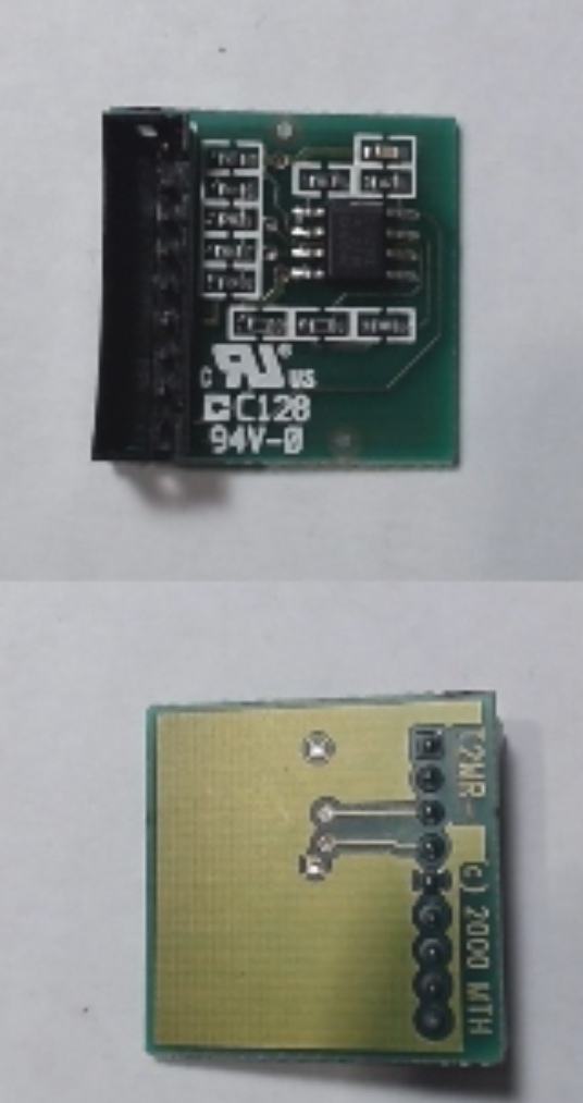
The socket in question has 8 pins, while the plug has 9 pin holes.
IMG_5457
Not all the pin slots are filled. I’m temped to shear off the extra and then find a way to keep it down.

Am I missing something bigger here? I’ve done these before and they are usually just drop ins.

Any help is appreciated!

Attachments

Images (2)
  • Board
  • Plug: (Pardon my fingers)
Last edited by BBasalik
Original Post

Replies sorted oldest to newest

Not all the pin slots are filled. I’m temped to shear off the extra and then find a way to keep it down.

DO NOT DO THAT.

Am I missing something bigger here? Yes, PS2 Premier engines often used the mux board system, one in the tender, one in the engine to give more features (lights) than the standard tether harness provides.

Mux wiring is NOT compatible with non-mux wiring- meaning never mix tender and engines.

Vernon,

Just for my own sanity, can I assume that with the tender MUX board (which I just ordered,) there is no tether from the MUX board to the main board?
Can I also assume then that the 8 pin connector and 2 pin connector are blank? There doesn't seem to be a slot for them.

In all fairness, this is my first PS2 3-Volt "Premier" stacker project. Everything else up to this point has been Railking for 3-Volt.

Correct, NOTHING plugs into the 2 pin connector on stacker in this engine (that socket is for motor drive signal in a multi engine diesel set to provide signal to a trailing analog slave board), and the 8 pin socket might not be utilized in all cases. The 8 pin socket is also lights- but again mux board is used because of limitations between the engine and board mounted in the tender.

You might want to review wiring diagrams specific to premier engines and mux systems before taking on such a project. Yes, your experience with railkings and that limited harness pinout- headlight ONLY is very different.

This is plain jane non-mux wiring engine side

steam tether

vs much more complicated MUX wiring

The motor leads go there because that's how MTH "regenerates" the PV voltage.  This saves them one wire in the tether.

See if this helps your understanding?

PS2 Steam Locomotive [2-chan mux) SchematicPS2 Steam Tender [2-chan mux) Schematic


example https://ogrforum.ogaugerr.com/...-premier-steam-setup

That one was in place. I saw it in there when I went to check the smoke unit. Wiring was intact too. The engine was essentially untouched.
(Side note; I'd wish they would re-stock that part. I've got another engine low on the priority list that could use one. I may end up converting that one to blunami in the end.)

The tender was missing a couple things. It had all the wiring, pots, switches, and rear lamp, but it was missing the battery holder and oddly enough the straight to 90 Degree tether.
I did get a new tether, and heatsink to go with the stacker board.

The wires for the battery were still there, as was the heatsink for the missing board. It's almost as if someone was planning to upgrade the engine at some point, or stripped it for some parts.
Quite peculiar.

I doubt you have a complete mux tender harness set up.  That connector must have 5V and PCB Ground, IL, HL as minimum along with the output to the tether to the engine.  If not wired up correctly you risk burning up the tach reader and having no speed control as the engine mux handles the ground to tach reader with current limiting resistor.

If the tender has markers or an AUX light you should have an 8pin connector for those functions.  G

Add Reply

Post
The DCS Forum is sponsored by

OGR Publishing, Inc., 1310 Eastside Centre Ct, Suite 6, Mountain Home, AR 72653
800-980-OGRR (6477)
www.ogaugerr.com

×
×
×
×
Link copied to your clipboard.
×
×