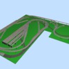
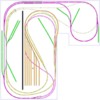
This is my latest design was wondering what everybody thinks. I'm looking to be able to have at least 2 trains running for my youngest grandsons(2 and 5) to watch and still be able to make up trains and do some switching with the oldest who is 12.

   The purple line is one main and the yellow is another. They are basically loop to loop with one end of each loop disappearing under the table. The orange is a small yard which will have engine facilities,and the green are the sidings. 

   The minimum radius will be O54 but most will be O63 or larger.  


    The drawings were done with SCARM software.I am going to be using gargraves track and ross switches. 


     I guess I am asking if anyone can make any suggestions or improvements.


snapshot

complete

Attachments

Images (2)
  • snapshot
  • complete
Files (1)
Original Post

Replies sorted oldest to newest

Hi old toymaker,

One major issue was observed. The track spacing. The purple at the north end' the yellow in the north west corner are 2.5" center-rail to center- rail and the purple in the southeast corner is 3.15".


Turn on rails in the settings 2D view and use the measure tool.


3.5" may be as close as you want to get for a yard, 4.5" on a main. I don't know the exact width of the Gargraves ties, but to get 2.5" you'll be cutting a lot of ties.


I usually pick a start point somewhere on the layout that the whole layout is indexed to. 3.5" from the edge somewhere. (sets center rail from edge) Then, when you build, start there and the rest of the spacing will be as designed. Mark the track joint on the plan. SCARM is very accurate.


That being said, some of the tracks look very close to edge. So, again, get the actual width of the Gargraves ties and allow for ballast.


You may want more height between levels in case you have to reach in to the lower level for an incident. Turn -off terrain in 3D view and rotate to look in.


If this isn't a walk-around, you'll need to consider access to the western edge with hatches or an over the layout creeper from Micro-Mark.


It stinks with SCARM that you can't do negative elevations, but the author says that won't happen, so , you've approached this correctly for a multi-level.


Is the black line in the center a view block?


Looks like it will be fun.


Last edited by Moonman

I noticed that many of your "in the loops" siding were straight lines, as though laid

with straight sections of track.  More prototypical and more interesting, as well as

providing more room for structures, roads, and scenery, would be some of those

sidings paralleling the main, or curving away, perhaps as "S" curves.  To me that

would make it look less artificial.  You could still have a straight section at platforms,

although that is not necessary, and a curved platform woudl add interest.

I was not sure how accurate scram was and the track on the loops( purple and yellow in the north and north west) will be almost tie to tie as trains will never be passing each other in these areas, I thought I could get away with the closer spacing to gain a little room same with the southeast corner. I will be using gargraves flex so the radius for all the corners will vary slightly but I hope to maintain the 0-54 as my minimum. I will work on the purple  line in the northwest corner to have more spacing I am not really proficient with scram yet especially with the elevations. The lower track will be buried under the upper, from my older HO layout I did learn to make the track accessible from below. the spacing from the top of the rails in the lower section to the bottom of the ply of the upper section will actually be about 7 inches.

   The North end and the far east end are against walls, The west end has about 2 and a half foot space and the south has about 4 foot space to walk around. I do have a special ladder I made to get over the top of the layout so I can reach those hard to get at places. I am trying to keep all my switches easily accessible, I believe those would be the places prone to having incidents.

   Yes the black line is a block between the interchange on the west side and the yard. 

  I guess I need to do some more work on the design Thank you for pointing those things out. This is why I posted I could use all the help I can get as I am not very good at the designing part of hobby.

You have a good plan designed.


A little more than 7 inches may better for hand and arm room.


When you color the tracks any changes to height will effect only that color. I see that you have the second level at 6.5". So, 7" for clearance + 1/2" plywood or 1" foam + 3/8" for roadbed(if any).


I just looked at the edges and the clearances look ok. At least 1" or more everywhere.


I made a change to the file to create a 12" view block for 3D effect. Check out the file in 3D. Also, look at TWTrainworx BNSF layout under layouts for a great layout division example in Traindame's Blog.


There is one track elevation off in the yellow north east curve.


I like how you split the elevation change between layers.


It looks pretty close to ready to me.


Keep virtually running a simulation to be sure it operates how you want it to work.


Attachments

2 questions, will you have access to all sides of the layout?  A ladder may be nice but that is going to get old real fast.  The yard appears to be quite a stretch from the tables edge.  How do you plan on handling the inevitable derailments in this area?

One other thought, if you are building this for kids layout height will be something to consider however, you will have to have access to the buried track below so higher in my view would be better.  


I did a little tweaking, the spacing in the northeast corner has been opened up to about 41/2 inches also played with some of the sidings. I changed the elevations to reflect the actual spacing of the upper and lower level. I am having a problem at the north end around the bridge, I can't get the track to join.

   As far as access there is a 28" walk way on the west side, the south side is open and the space on the on the east side. The far east is against a wall and the north side is a wall.

    The bottom level is 39 inches off the floor. My oldest grandson is pretty tall and will have no trouble and there will be steps for the younger ones to watch. Besides the layout is as much for grandpa as it is for the kids, it was a good excuse to get grandma to agree to the expense .

     The ladder I mentioned is more like a platform that folds out of the way and is quite comfortable to work off of.

      I've added the latest drawings.


complete 2

Attachments

Images (1)
  • complete 2
Files (1)
Last edited by old_toymaker

I only see one track joint in the NNE before the bridge that isn't fitting. This is due to misalignment.


The default connection tolerance is very small in SCARM, which I like. When building the layout, that joint is close enough that you will be able to wiggle fit it. It appears you solved the others.


I was thinking about how long the train will disappear on the lower level in the tunnel on the SE side of the large area. Perhaps some viewing holes and some lighting under there would be cool.


I also looked at the curved sidings. Can't really service an industry\business with a curved siding. Is it an abandoned line or something like a mine cart? They just look strange to me.


The photos in the post aren't showing for me.

Yeah, that fareast just begged for that treatment. The 3d stuff is fun, but I don't do a lot of it, unless someone is a "need to see it" person.


I do see some interesting possibilities for cutting out some of the upper deck between the east main and the yard, but it would have taken too long to 3D for you. It would also be a lot of extra build work and scenic time. Something just wants me to expose that lower loop somehow.


Keep us updated as you progress. Nice job on the long yard lead(s) by the way. 


Did you check out the BNSF layout for the center view division?

Thanks for the help the new stuff does add a lot. I was thinking of opening up some of the track at the far east but i'm not sure how i can do it. As far as build time goes the winters here in ct. can get long and boring so something to keep me out of the wife's hair is always welcome. 

  I should have mentioned that I model the New Haven RR around the late 40's to late 50's.

  I did check out the site that was awesome. More ideas but how to work them in my never ending problem.   

 again thanks so much for your help

Gary

Add Reply

Post
The Track Planning and Layout Design Forum is sponsored by

AN OGR FORUM CHARTER SPONSOR

OGR Publishing, Inc., 1310 Eastside Centre Ct, Suite 6, Mountain Home, AR 72653
800-980-OGRR (6477)
www.ogaugerr.com

×
×
×
×
Link copied to your clipboard.
×
×