I would have had a whole lot more trial and error without Dave!!!! Mostly error! ![]()
@Mark Boyce posted:John, Nice job with SCARM. The plan looks great with the added sidings for various industries. Again, I am not up on yards and engine facilities to critique that area, but I'm sure someone will come up with some suggestions. All I can say is I'm glad you have room for that much car and engine storage!!!
Thanks Mark
sounds like you are in favor of keeping all the yard tracks
John, the disconnects show up as small gray arrows as soon as you turn off Heights. Sometimes they're not disconnects, they're differences in heights between the 2 tracks. One looks like a stray track in the yard. I've had cases where I've fixed the heights, but they show back up the next time I open the file.
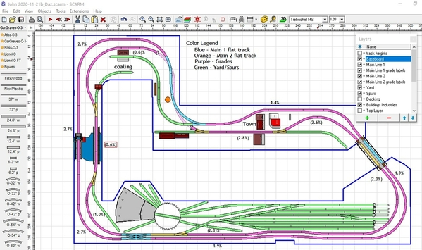
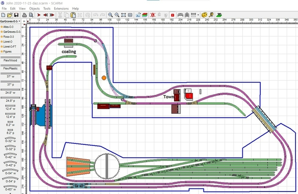
Here's a new version with the corrections.
Attachments
@Aegis21 posted:Thanks Mark
sounds like you are in favor of keeping all the yard tracks
Absolutely, John! Someday you may wish you had more! ![]()
Nick, you're right, the requirement to use the 4-way switch drove the yard design.
Here are some alternate designs where I moved the bottom spur to the top, moved the 4-way lower and added a runaround. I left the 30° crossing in, but I see no practical use for it and I don't like the curved lead to the TT. Then I removed the crossing and 4-way.
Attachments
John, unless you have some practical ideas for buildings that would look right in a yard scene, I also support keeping as many storage tracks as you can. However, it’s your layout and only you know how you want to operate.
Dave, I like the second one better. It actually allows for a the tracks closest to the wall to be a little longer, and doesn't cut any tracks shorter.
Thanks, Mark. I don’t have any experience with yard design, I just think the 2nd one without the 4-way looks smoother. I don’t think there’s anything wrong with the 1st. It’s tough to design a yard when there’s not enough room for a longer lead track off the mainline. I probably should have added another crossover on the bottom 2 tracks, so they could be worked without fouling the mainline. Trouble is I don’t know if John even wants to work the yard with a switcher to move cars around. Me? I’d just have consists stored for engines to pull out and they’d probably never be reconfigured. 🤪
Dave, just storing consists ready to go is the way I would do it. However, if I had the yard with the right crossovers, maybe I would give switching a try and like it. Well, I don't need to worry about it on my little layout. ![]()
I agree, Mark. Like you, I don’t have the space, so I convince myself I don’t like switching 😱, but I really do like to watch more. I don’t like role playing on any level, so reconfiguring consists just isn’t in my wheelhouse. 🤪
Yes, I almost fall asleep watching the smaller scale guys do switching on their modular layouts at the Greenberg shows. The Pittsburgh Independent Hirailers just have 4 trains highballing around the layout and it is great fun!
@DoubleDAZ posted:John, unless you have some practical ideas for buildings that would look right in a yard scene, I also support keeping as many storage tracks as you can. However, it’s your layout and only you know how you want to operate.
@DoubleDAZ posted:Nick, you're right, the requirement to use the 4-way switch drove the yard design.
Here are some alternate designs where I moved the bottom spur to the top, moved the 4-way lower and added a runaround. I left the 30° crossing in, but I see no practical use for it and I don't like the curved lead to the TT. Then I removed the crossing and 4-way.
Hi Dave,
Great job as usual!! First impression - I like the second drawing better. At this point I am not sure of running a switcher in the yard, however it appears this will facilitates that and if I want to store consist there then that can happen also, unless I am not understanding something.
I am not sure if the yard tracks can fit under the main lines, I don't have access to scare right now so I cannot check. If I remember the main lines are not elevated that high over the end of the yard. It doesn't look bad to shorten the yard tracks closest to the wall
Also no buildings are planned for yard area yet
Any thoughts?
EDIT: Well, I see you guys beat me to it! But here is another idea, for what it's worth:
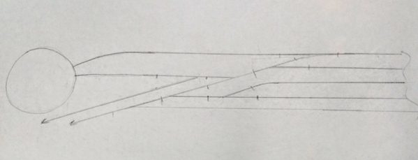
Well, I don't use track planning software, but here's a sketch. This would be the top portion of your yard (nearest the aisle). The top two tracks handle trains arriving/departing (the train parks on one track, the other is a run-around). The rest of the tracks on the right side are regular yard tracks--I didn't bother drawing the majority of them. Both of the two diagonal tracks on the left meet the inner loop main line, preferably to the right of the double crossover. So the idea here is that while the switch crew is busy moving up and down the yard ladder (right-hand diagonal track which all the yard tracks come off of) an inbound or outbound train can still access the top of the yard by using the bypass track (I believe Armstrong calls it a thoroughfare track) on the left. And, the switch crew can easily access those top two tracks from the yard ladder.
This will, of course, shorten your yard, and your longest train will be dictated by how long you can make the designated arrival / departure track. However, it can potentially double the amount of fun your yard can produce at any given time, since you can have two people working in without one having to wait for the other to be done before doing their own task.
A problem with this design is that your yard does not have much of a lead. That means that a switch crew moving a long cut of cars could end up backing onto the main and getting in the way of the arriving/departing train after all. I don't see an easy fix for this, but it would not be too much of an inconvenience for people to simply remember to take fewer cars at a time and not back onto the main.
Another idea that comes to me just now is to expand the top section to three tracks. The third will be a little longer than the others and can be the A/D track. The top one would host cabooses. The middle would be a shared runaround for the other two. Since you only access the caboose immediately after a train arrives or immediately before one departs, this should work OK from the perspective of the switch crew staying out the way of the other train.
One last thing: at present, you have the yard ladder leading through one side of the Ross 4-way. This creates an awkward S-curve. It might be better to have a switch in the ladder (possibly a curved one, rather than a #4 or #5) and let the 4-way originate off the diverging leg of that switch. This, too will cost you some length, and might not be worth it after all, but since you can use the software, it costs little to experiment.
Attachments
Good morning, John.
FWIW, I only ran the yard tracks under the mainlines because you had several set as tunnels. A little more on that later.
Regardless of which configuration you ultimately choose, the biggest problem with the yard is the lack of a longer lead track. Now, there's nothing you can really do about that, but it does affect how you can use the yard. As it is now, a switcher can't even move 1 car from the bottom track (track 1) and clear the switch without temporarily fouling the inner mainline. That's why I placed the crossover between tracks 3-4. As the illustration shows, a train can pull in on track 3, the engine can then uncouple and move through the crossover to track 4 to escape. A switcher can then pull cars 1 at a time from track 3 using the same technique.
As you can also see, track 3 only has space for a train with 8 cars. However, if you raise the bridge to 7", the grades go from 1.9/2.3% to 2.0/2.4% and give you an extra .5" of clearance under the mainline tracks. Then another crossover could be added between tracks 1-2 and you'd have 2 arrival tracks, one slightly longer. However, that moves track 8 and even though I didn't remove it, it might better to do so because it's close to the edge.
Now, raising the bridge would mean the inner mainline track on the other side of the bridge would go to 3.1%, but that could be fixed with a reconfiguration of the switch and buildings.
The bottom line is you can use the yard 2 ways. If you use it for storing complete consists and not for switching, then arriving trains would simply back into their respective slots and you could save the cost of 4 switches for the crossovers. However, if you keep the crossovers and use it for switching, then arriving trains would pull in on tracks 1 or 3 for a switcher to reconfigure consists. Basically you could use it both ways, storing consists when it's just you and for switching when the mood strikes or when you have someone visit who enjoys switching. When switching, tracks 1-2 and/or 3-4 would need to be emptied for arriving trains or configured with departing trains.
Attachments
@DoubleDAZ posted:John, the disconnects show up as small gray arrows as soon as you turn off Heights. Sometimes they're not disconnects, they're differences in heights between the 2 tracks. One looks like a stray track in the yard. I've had cases where I've fixed the heights, but they show back up the next time I open the file.
Here's a new version with the corrections.
Dave, This probably won't fit but I keep looking at this thinking if the yard had a run through it would be really useful. Just for fun if the short green spur west of the 2 bridges went across with a third bridge and connected with the outer track that feeds the switch ladder. I don't use scarm so I have no idea if you could get enough of a curve for this to work.
@DoubleDAZ posted:
That would have been cool if the bridge could be straight. Thanks for humoring me. The whole layout is loaded with potential and your ability to work through different issues is remarkable.
@Aegis21 posted:Hi Dave,
Great job as usual!! First impression - I like the second drawing better. At this point I am not sure of running a switcher in the yard, however it appears this will facilitates that and if I want to store consist there then that can happen also, unless I am not understanding something.
I am not sure if the yard tracks can fit under the main lines, I don't have access to scare right now so I cannot check. If I remember the main lines are not elevated that high over the end of the yard. It doesn't look bad to shorten the yard tracks closest to the wall
Also no buildings are planned for yard area yet
Any thoughts?
John, I agree on the second design. As you say, the yard tracks closer to the aisle could be a little longer maybe allowing one more car. I don't think increasing the grade on the two mainline tracks enough to let the tracks extend underneath would gain you a whole lot more.
However, if you worked on building the mainlines along the wall behind the yard first, you could mock up different grades just to the end of the table where the lift up bridges are by just putting different heights of blocks of wood or even boxes or cans under track and see if the increased grade is acceptable. Also by just laying in a couple yard tracks temporarily, you could see if it is worth it. My open trestle grade, short yard, the engine facility above, and the last industrial siding were done in this way. Dave had figured the grade that I later decided to use the trestle, I just played with it to see if I could make the grade less. Actually both grades were adjusted on the fly when I discovered I needed a little more clearance for the underpass. On the engine house wye, it was totally trial and error after I pulled the plug on buying the used engine house, then Dave helped me refine the design for the wye to the engine house in scarm.
I think building this way doesn't make you commit to either scenario until you actually try it out. Then you can build the rest of the way around the room to match things up at the lift up bridges.
Thanks for the kind words, Dave. Even using O54, the bridge wasn’t straight, just not enough room. I even tried changing the yard to O72 switches, but that doesn’t work at all.
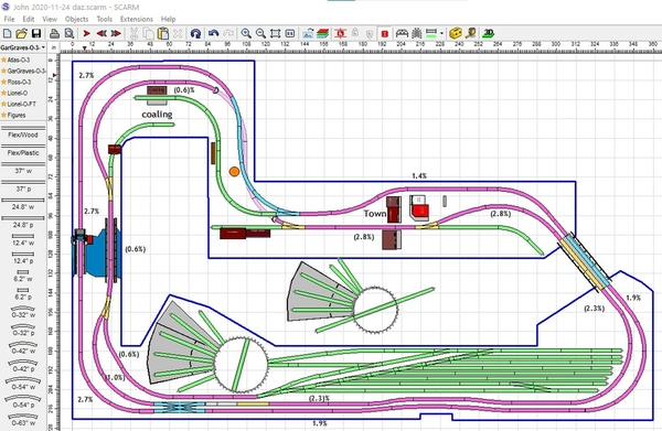
Ok, John, here's a clean version with the yard ending before the mainlines pass overhead. I reconfigured the runaround track because I didn't like the curved entry to the TT. I moved the single crossover to tracks 1-2 because track 1 has the most space for an arriving train to pull in and let the engine escape. You can still back trains into any of the slots if you don't want to switch. I smoothed the exits off the bridge going north. I rotated the Bascule bridge.
Attachments
I was working on a way to add a full length yard lead from the river bridge switch on the left when I noticed the TT&RH are not correct. The RH is actually a 3-stall model with a 26” TT, but at some point it was turned into a 4-stall with a 28” TT and I never noticed. My laptop is installing an update, so I haven’t been able to check the footprint, but I’m pretty sure it’s incorrect. I think the only 4-stall file I have is for an Altoona RH, so I’m going to have to play around with things a bit. FWIW, if the RH/TT can be shifted up a bit, it looks like a lead track can come off the bridge switch and avoid a switcher fouling the main.
Ok, here's what I've come up with as another alternative to explore. As you can see, I added a longer lead track into the yard. It's on a 0.6% grade. I then redid the RH/TT configuration and think I've got the RH placed right on the 28" TT.
NOTE 1: You can't just add another whisker track inside the RH simply because it will fit. The engine has to be able to get through the doors, etc. If you want a 4th stall, you need to add 1/3rd of the RH to one side or the other, not just add inside tracks.
NOTE 2: Since the TT is only 28", it doesn't make sense to buy/build an RH with more than 1 stall capable of holding longer engines. I would need to be at the end of a track that runs straight across the TT into the RH.
Attachments
Dave, I don't see the drawing.
Thanks, Mark, should be fixed.
Looking good, Dave!
Wow I should have computer / internet problems more often! Gone for a bit and everyone dug it and did an amazing job! Thank you nickaix, Dave Ripp, Mark, and especially DoubleDaz Dave!!! Outstanding suggestions and remarkable results!
Now that a RH & TT are not only feasible, but actually on the layout. Is it possible to have either a four stall RH or a larger TT or Both? And would it mean sacrificing any of the great ideas and suggestions so far? I truly love all that has been done while I was in internet never never land. Dave you have taken my errors and adapted/solved the problems they caused. You all are incredible!
Please anyone/everyone let me know your thoughts on the last iteration of the yard as far as storage and switching operations are concerned. ALL comments are an educational process for me.
Once the yard is "finalized" by all your comments and help, the next list to go down is the lists of wants:
Here is a list of wants in no particular order of importance...
Junkyard area with gantry crane and loading/unloading area
Icing station with loading/unloading track
Coaling/Mining Area with coal elevator
Freight loading/unloading area near town or in town
Town with streets,
Last three I have preliminary areas on layout, however as this is my first big layout, all ideas are not only welcome but needed!
Again Thanks to all !!!
@DoubleDAZ posted:Ok, here's what I've come up with as another alternative to explore. As you can see, I added a longer lead track into the yard. It's on a 0.6% grade. I then redid the RH/TT configuration and think I've got the RH placed right on the 28" TT.
NOTE 1: You can't just add another whisker track inside the RH simply because it will fit. The engine has to be able to get through the doors, etc. If you want a 4th stall, you need to add 1/3rd of the RH to one side or the other, not just add inside tracks.
NOTE 2: Since the TT is only 28", it doesn't make sense to buy/build an RH with more than 1 stall capable of holding longer engines. I would need to be at the end of a track that runs straight across the TT into the RH.
Dave all your work is not only magical, but so appreciated and welcome. Simply awed at your scarm mastery and problem solving ability. It appears that the baseboard for the layout is getting to its final stage. I'll be doing mostly L-girder workbench, however the yard is flat and seems L-Girder would be less desired for that entire section. Dave, or anyone else please comment on benchwork style and which would be best for which sections. Also, should I consider making the TT removable for access and any needed repairs?
Again Thanks Dave!
John, I have used both open grid and L-girder, and I don’t really have a preference. One thing, L-girder takes more height, and since I must use under the layout storage, I am getting a little more height for storage and it is easier for wiring. Since I bought Mianne for part of the layout, it is open grid. The rest is cantilevered with brackets off the wall. So to stabilize the ends, it is in effect open grid using the wall for part of the grid. This is the largest layout I have ever built, and the first around the walls. My L-girder layouts were so small, and I don’t think I made use of the benefit of that construction. I guess in the end, I favor open grid. Let’s see what some others who have experience with larger layouts have to say.
I would think you would want to make the turntable easy to remove for maintenance. I have never had room for one even in smaller scales
John, there's no reason not to use L-girder throughout. I think you're confusing framing (L-girder) with decking (open cookie-cutter and flat panel). Since you have a lot of different elevations, you'd use cookie-cutter decking with risers under the tracks in those areas and then flat panel decking under the yard. When it comes to the town areas, you might use a combination of flat panel decking with risers on top of the decking for the elevated sections.
And Mark is absolutely correct, L-girder adds to the depth of the framing below the decking and can limit movement, storage and access underneath.
When it comes to the RH/TT, the width and length of the RH are determined by how far it is from the TT and that is determined by the angle of the stalls. Atlas stalls are set wider allowing them to be closer to the TT whereas Altoona's are set narrower meaning they have to be further from the TT in order for engines to clear the doors. As you can see in the 1st photo, the Atlas 3-stall fills a space approximately 40x40" measured from the edge of the TT. The space needed for 4 stalls grows to 40x50" or so while Altoona makes a 4-stall RH that is narrower, but longer at 30x63" as measured from the center of the TT. Shown are Millhouse 28" and 34" TTs.
The 2nd photo shows were I added the 34" TT and cut 1/3rd of the RH to make another stall to show what that does to the space needed. As you can see, the bench work needs to be that much deeper and narrows the aisle some.
In the 3rd photo I kept the 34" TT and replaced the Atlas RH with an Altoona RH to show the difference. You can see the reduced depth and wider aisle. You can also see the outline of the 33x63" footprint. In this case, the RH has 2 extended stalls for larger engines. Main whiskers are 32" inside and extended are 35". I don't know about the Atlas model, they just say distance from TT to rear wall accepts 37.25" of track and some of that is outside
I haven't optimized placement. I've never seen a TT prior to being installed, so I don't know how much clearance they need for installation and support. Based on drawings I've seen, it looks like they have 4 tabs for mounting to the underside of the decking and I think the TT just fits a 34" hole, so the hole needs to be placed so a passing train on the mainline will clear a large engine as it turns.
Attachments
Whatever you do, John; Don't use the L-girder or open frame stringer for a soldering iron hanger. I was soldering under the L-girder layout over 30 years ago and was looping the soldering iron cord over a joist when not in use. I forgot about it and jammed my wrist up against it, sizzling a hole in my wrist. ![]() My wife the registered nurse looked at it and was impressed that I cotterized it in the process. We both had to laugh as the flux was a bit of an issue cleaning out. It went right between two tendons. I still carry the white scar.
My wife the registered nurse looked at it and was impressed that I cotterized it in the process. We both had to laugh as the flux was a bit of an issue cleaning out. It went right between two tendons. I still carry the white scar.
@DoubleDAZ posted:John, there's no reason not to use L-girder throughout. I think you're confusing framing (L-girder) with decking (open cookie-cutter and flat panel). Since you have a lot of different elevations, you'd use cookie-cutter decking with risers under the tracks in those areas and then flat panel decking under the yard. When it comes to the town areas, you might use a combination of flat panel decking with risers on top of the decking for the elevated sections.
And Mark is absolutely correct, L-girder adds to the depth of the framing below the decking and can limit movement, storage and access underneath.
When it comes to the RH/TT, the width and length of the RH are determined by how far it is from the TT and that is determined by the angle of the stalls. Atlas stalls are set wider allowing them to be closer to the TT whereas Altoona's are set narrower meaning they have to be further from the TT in order for engines to clear the doors. As you can see in the 1st photo, the Atlas 3-stall fills a space approximately 40x40" measured from the edge of the TT. The space needed for 4 stalls grows to 40x50" or so while Altoona makes a 4-stall RH that is narrower, but longer at 30x63" as measured from the center of the TT. Shown are Millhouse 28" and 34" TTs.
The 2nd photo shows were I added the 34" TT and cut 1/3rd of the RH to make another stall to show what that does to the space needed. As you can see, the bench work needs to be that much deeper and narrows the aisle some.
In the 3rd photo I kept the 34" TT and replaced the Atlas RH with an Altoona RH to show the difference. You can see the reduced depth and wider aisle. You can also see the outline of the 33x63" footprint. In this case, the RH has 2 extended stalls for larger engines. Main whiskers are 32" inside and extended are 35". I don't know about the Atlas model, they just say distance from TT to rear wall accepts 37.25" of track and some of that is outside
I haven't optimized placement. I've never seen a TT prior to being installed, so I don't know how much clearance they need for installation and support. Based on drawings I've seen, it looks like they have 4 tabs for mounting to the underside of the decking and I think the TT just fits a 34" hole, so the hole needs to be placed so a passing train on the mainline will clear a large engine as it turns.
Thanks for clearing up the bench work support versus decking/cookie cutter designs. As for the TT RH it looks like keeping the aisle clear and access to the corner the third pic looks best. I was wondering if the Brennen RH would fit. Don't know if budget can handle millhouse/Brennen TT/RH but if it wouldn't fit then that throws that out that idea. Also I do not anticipate buying a Big Boy Loco, with that said, what is the most used TT?
Actually, John, I’d never heard of Brennen, so had to look it up. Turns out they have a good explanation of roundhouse configurations, especially the part about track spacing along the turntable. They also explain the relationship between distances from the TT and how they affect track alignment inside the RH. Altoona documentation explains this too and includes illustrations. However, Altoona just shows the track misalignment whereas Brennen kind of explains how to curve into the RH so the inside track is aligned. I didn’t study that yet. Unlike the other brands, Brennen provides the dimensions of their stall making it easier to create one in SCARM. I haven’t worked out their explanation of angles and I don’t have time tonight to play with things to see how one would fit, so I’ll try tomorrow.
Hi Dave, It looked like Brennan RH and millstone studio TT mate very well together, they are definitely pricey. Not sure if they are worth the costs. They seem to be extremely well built and are the high end of their product lines. Hoping to get feedback from forum if someone has used these on their layout.
Thanks again and again for all your help and knowledge.
John
John, I'm not sure Brennan mates to Millhouse all that well, but here are what the extremes would look like if I understood the documentation correctly. And that's a big IF at this point. The biggest problem I have with their description is they say a 3-stall RH measures 18 x 31.75 x 26.25 and we all know RHs don't have straight fronts or backs, hence the name ROUND house, so I assume the measurements are from the outside corners of both the front and back straight across. It also says the min and max distances from the TT is measured from the center of the TT to the center of the front door. The bottom line is I can't vouch for the accuracy of what the photos show.
The first photo shows what I believe their chart shows. The top configuration is the optimum distance for the RH from the TT. This allows the whisker tracks to be straight. The bottom configuration is the minimum distance and note how the leads have to curve in order for the tracks inside to be straight. The amount of the curve changes depending on how far the RH gets from the TT. Also note how close the tracks are on at TT in the top configuration. They explain that you have to trim the front ties so the rails will meet those on the TT.
Anyway, the second photo show the min configuration on the layout and the third photo shows the max. As you can see in the third, the footprint seems rather large and I don't know how advisable it is to curve the whiskers. If you do, you have to make sure engines clear the doors as they enter and exit.
One other note is that whiskers can be curved for other RHs too, so this is not unique to Brennan.
Attachments
One of the posts above requested installation photos. F.W.I.W., I have five TTs all with flat deck installations. Two are Millhouse One Bowser and two custom units.
They are mounted on flat deck platform modules specifically framed out for a TT.
The above TT preps are typical of how I get ready to install Millhouse.
The above inverted TT module is going to be added to another module round end for turning locos only. The next photo is of this module with TT in place.
The above TT inverted module is a prep for a drop in of a 32" flanged TT pit in lower photo. The 32" TT serves the dead end of two branch lines coming from opposite directions.
The 26" small TT in the corner is for turning small power coming in from the other room on a higher level. It has similar construction of the add on module photo above.
This is a staging room off scene.
Attachments
Nice photos, Tom, especially the bare TT that shows the tabs for mounting that appear to be 1-1.5” long. The one with the TT in the corner shows how close the TT can be to the edge. I saved them for future reference. As always great workmanship.
Tom, with five turntables and probably others on layouts you have built for others, I would say you have come up with excellent ways to do it!
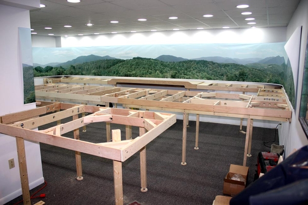
Tom, Great photos and I can only add to Dave and Mark's comments to say you have a ton of good experience which is invaluable! This is a tremendous help. I was just starting to layout L-girder framing to see how it blends or works with track layout. Perfect timing! Here is what I have done so far as I understand L-Girder, which is assuming a lot! Please any and all comments are GREATLY appreciated! Everyyone have a wonderful and safe Thanksgiving. Even in these horrid times of pandemic and division, we all have lots to be thankful for today.
Thanks to everyone on this forum and may God Bless everyone.
Sincerely John
Attachments
John, Yes you have the concept of the L-girder method. You have done a great job drawing it in on SCARM!! ![]() Having never built a layout nearly that large, I can't comment on your leg spacing or the long reach between two L-girder pairs in the upper left. Also, I think you would need to do a variation under the turntable site to accommodate Tom Tee's framing method. I would think Tom will chime in on that.
Having never built a layout nearly that large, I can't comment on your leg spacing or the long reach between two L-girder pairs in the upper left. Also, I think you would need to do a variation under the turntable site to accommodate Tom Tee's framing method. I would think Tom will chime in on that.
@Mark Boyce posted:John, Yes you have the concept of the L-girder method. You have done a great job drawing it in on SCARM!!
Having never built a layout nearly that large, I can't comment on your leg spacing or the long reach between two L-girder pairs in the upper left. Also, I think you would need to do a variation under the turntable site to accommodate Tom Tee's framing method. I would think Tom will chime in on that.
Mark, totally agree on needing to change around TT and recheck spacing. This is a first draft so to speak and a starting point. I have started another topic only dealing with benchwork. not sure if that was a good idea to split things up or not... As for drawing it on scarm, well the track is on the floor and the supports are in the air! LOL ![]()


