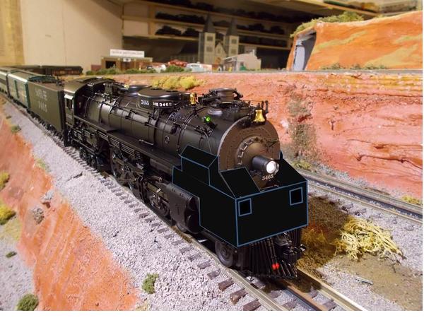
On page 233 of Larry Brasher's Santa Fe Locomotive Development, there is a photo of ATSF Northern 3766 with a pilot doghouse mounted during testing on Sept 23, 1938. In deference to the copyrighted nature of Brasher's 2006 book, I am not attaching a copy of that photo, but instead a photo of one of my ATSF Hudsons where I have sketched out what the doghouse looks like and how it is mounted.   Apparently an observer and test equipment of some sort rode in it.  The photo looks as itf it is made of riveted steel, not wood.  The text discusses dynanometer tests and concerns about rail loading.  

On page 243 there is another photo from 1939 of ATSF Texas 5007 with one (but clearly not the very same one, a bit different design, mounted in the same place.  The text says it housed test equipment during dynanometer runs but does not talk about an observer in that one ( but doesn't say there wasn't).  


Did railroads own several of these or just built them as needed?  What exactly did they house?  As anyone on this forum ever modeled one in O gauge?


pilot doghouse

Attachments

Images (1)
  • pilot doghouse
Last edited by Lee Willis
Original Post

Replies sorted oldest to newest

These doghouses were only used when testing and documenting locomotive performance. One or two men rode up there, inserting indicator cards into a device attached to the valve gear that diagrammed the action of the valves, steam chest pressures, back pressure, speed, etc.


Test were run at various speeds, throttle positions and cutoff settings so the locomotive manufacturer or railroad involved had a documented record of the locomotive's performance.


When the tests were completed, the doghouse was removed.

Last edited by Rich Melvin

There are pictures in Alvin Stauffer's "Thoroughbreds" of the original New York Central J-1 Hudson #5200 with a similar structure on the pilot during testing. It looks like a custom built affair. The accompanying text says that the structure protected test personnel and their instruments, which were used to measure cylinder and valve operating conditions.

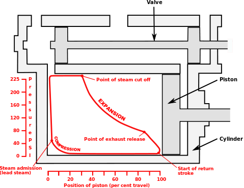
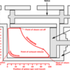
The "Indicator Cards" produced by the instrumentation on the locomotive produced diagrams of pressure as it related to valve position.


Here's an illustration of what the indicator card was measuring. That this is NOT an actual indicator card...it is a well-done diagram of what the indicator card is measuring.


steam indicator card

The cutoff represented in this diagram is set at about 30% (fairly short) and the steam works expansively for the remainder of the stroke.


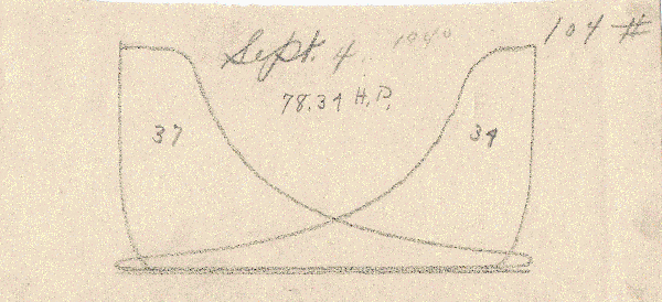
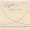
Here's an actual indicator card:

Steam Indicator Card

This card has two diagrams on it because it is showing the results from BOTH cylinders on one card.

Attachments

Images (2)
  • Indicator Card Illustration: Indicator Card Illustration
  • Steam Indicator Card: Steam Indicator Card
Last edited by Rich Melvin

The Timken locomotive had a dog house added to her right side during testing on the NP.  It was very much needed in a Montana winter.  The need to go to the length of building a dog house for people to occupy and take instrument readings also illustrates the degree of difficulty involved in remote data acquisition given the technology of the time.


Note the dynamometer car behind the tender.


See the Ron Nixon collection for more.


http://www.morphotoarchive.org/rvndb/


Last edited by Ted Hikel
Originally Posted by Number 90:
Originally Posted by OGR Webmaster:

One or two men rode up there, inserting indicator cards into a device attached to the valve gear that diagrammed the action of the valves, steam chest pressures, back pressure, speed, etc.

One or two brave men!

And, according to some discussion I found in Brasher's book and on-line, very uncomfortable, too!  

Post

OGR Publishing, Inc., 1310 Eastside Centre Ct, Suite 6, Mountain Home, AR 72653
800-980-OGRR (6477)
www.ogaugerr.com

×
×
×
×
Link copied to your clipboard.
×
×