


Bob, IS the gray wire connecting to the red of the markers and the green to the black? If not the polarity is backwards. Other wise we need to make sure the green wire moved from the 4 pin smoke, went to the correct slot on the 8 pin. G
George,
It was reversed. I had the green wire coming from pin 4 and the gray wire coming from pin 8 on the 8-pin connector, but at the marker lamp plug (yellow) the reds and blacks were reversed (remember, this yellow-plugged lamp harness is for the REAR marker lamps). Instead of yanking out the PS guts (again) from the tender I pulled the pins and swapped the wiring at the yellow plug.
Now I have pretty (un-prototypical) marker lamps and a headlight shining brightly ![]() :
:


(this photo was taken with flash so the front-mounted air pumps would show)
Can barely see the red glow of the marker in the photos (need to get closer or get a better camera).
About all I have to do now is add the numbers to the headlight, the lenses, put (back on) the stirrups steps on the rear of the tender, and add the coal load back.
Here's what the original Williams/Samhongsa 2-8-2 looked like when I received it:

Bob, Yes the Williams Brass engines present a more complex problem as I stated in an earlier post. Good to hear the jerkiness is out.
It is all about ratios. If the program for speed control is written such that when the tach reader counts 24 changes it knows the motor made one revolution, and based on the gear ratio and driver size the engine has gone x scale miles.
Your engine will use this same profile but your gear ratio and driver diameter maybe different. The only factor you can change is the stripe count. So you need to trick the program. If your combination of driver size and ratio is less than the MTH engine who's sound file you are using is; your engine travels less distance when the reader counts the 24 changes. So by removing a few stripes, the motor turns more that one revolution when the tach reader tells the program one revolution completed, so the engine has gone the same distance. G
If your combination of driver size and ratio is less than the MTH engine who's sound file you are using
George,
That's my real problem, I can't determine/find out what the driver size and gear ratio is of a MTH USRA 2-8-2.
I used this file "p021pusramikadoall020401afin_3v.mth" taken from loco 20-3075-1, but I never could find out what the driver size was. I would think ALL MTH USRA engines have the same size drivers and gear ratio.
You just set it on a track with the shell off. Rotate the flywheel, counting the revolutions until the drivers make one complete rev. There was a complete set of tach strips posted from the Hikel website that should allow you to print the correct sized strip. The key to this process is you have to know something about the specifications for the sound file being used. I'm sure someone here has done the computations on that locomotive type and should have the details. If I had one I'd do it for you. ![]()
John, His issue is he doesn't have the MTH engine the sound file being used from.
Bob if you e-mail Dave Hikel, he has that info I believe. G
George, that was my point, I'm sure someone knows what that gear ratio is, and then he can complete the computation and generate the tape. ![]()
I just emailed Dave, hopefully I'll have this solved soon ![]()
Originally Posted by Bob Delbridge:
PS...I'm still having trouble finding the correct tach tape, don't fully understand why Dave Hikel's method calls for something more than 48 stripes when MTH uses it as a standard. My steam chuffs, driver revolution, and speed are still a bit off. I timed the engine over my 1/3 mile mainline. It should have taken 20 seconds to go the 1/3 mile at 30smph, but I had to increase it to 35smph to get the 20 seconds.
Seems to me if your Williams goes 30/35=85.7% of commanded speed, then you need to have 85.7% of the 48 stripes or 41.1 stripes. Since stripes must be even, you'd use 42 stripes or 21 black + 21 white and live with an "uncorrectable" 2% speed error.
If your speed numbers are accurate and assuming Williams and MTH scaled the wheels properly (same diameters of the model), then MTH must be using a Gear Ratio of 18 instead of Williams' 21. 18/21=85.7%.
Stan, you were just about dead-on.
Dave emailed me with what he thinks it ought to be.
The MTH USRA engines had 32mm drivers and an 18:1 gear ratio.
I need a tape with 42 stripes measuring .081"
I believe I have the tap already printed out, so I must have been close at one point.
I'll try this out tomorrow!
I'm readying myself to upgrade the Weaver 4-6-0 I have and have a question.
Do all MTH tach tapes have 48 stripes?
If they've determined that is the number of stripes needed, why can't I simply take the flywheel diameter, multiply it by pi, then divide it by 48?
If I do that I get 48 strips of .062" wide.
I "guessed" at what PS2 engine to use on the Hikel website (not all engines or wheel diameters are listed). I chose one with a 1.525" wheel diameter, a gear ratio of 16:1, and 48 stripes as a standard.
The Weaver 4-6-0 has a 1.417" wheel diameter, a gear ratio of 22:1, and a flywheel that's .945" diameter.
If I do that I get 33 stripes of .090" wide, almost 50% wider.
The 4-6-0 has the same flywheel and motor as my Williams 2-8-2 I talked about above. On the 2-8-2 I made the flywheel larger by wrapping some double-faced tape around it, but can't do that on the 4-6-0 due to clearances.
The differing number of stripes is what's got me confused, since from what we've been told, MTH always uses 48 stripes.
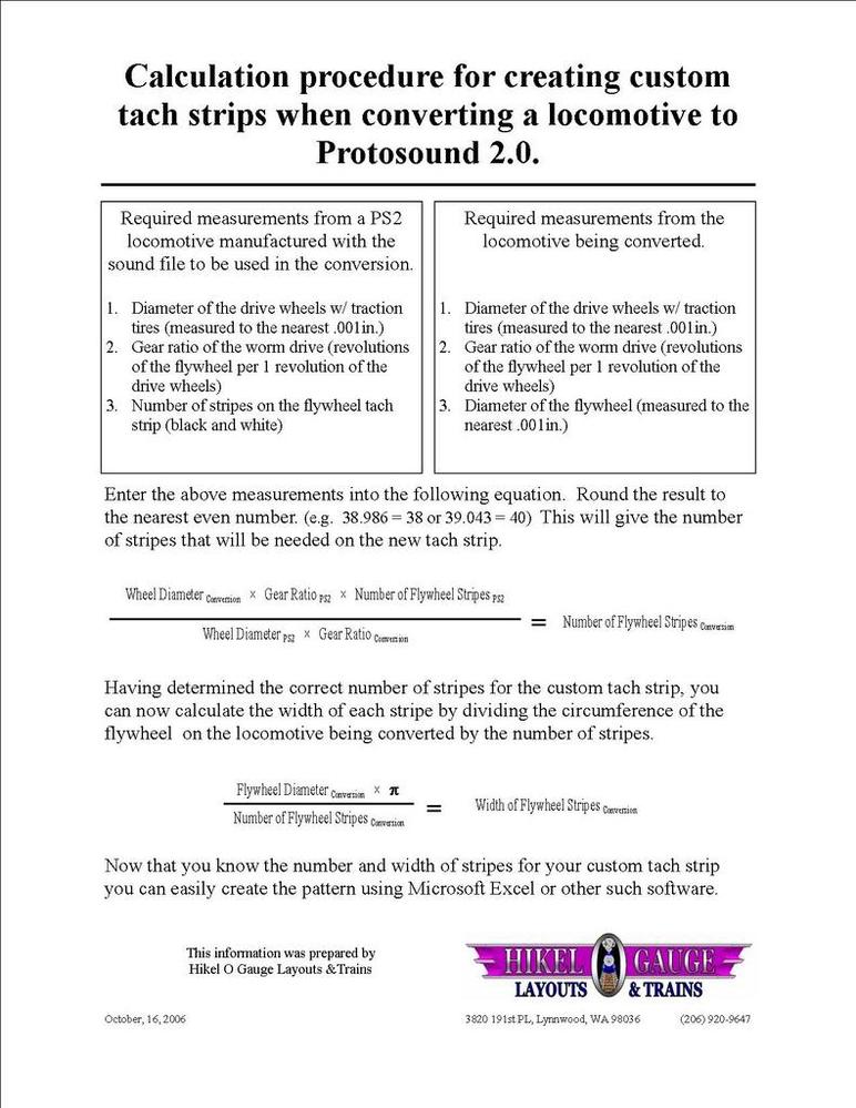
Actually, the number of stripes is related to the gear ratio. I believe Dave Hikel has posted a nice calculation sheet at times to determine the flywheel stripes.
Edit: Here it is, I saved it for future use. ![]()

Attachments
Images (1)
John,
That's what I used to get my tach tape, but I wonder why the numbers of stripes differ when MTH seems to use only 48 stripes?
I did the calculations for my 2-8-2, but could never get the engine chuffs to coincide precisely with the movement of the wheels. only when I recalculated at 48 stripes to get the stripe width did it come close to being right (still needs a bit of tweaking).
With this 4-6-0 I thought I'd get the jump on it (haven't bought the upgrade kit yet), won't hurt to put the tach tape on it now.
Originally Posted by Bob Delbridge:
SUCCESS!!!
I managed to get the sound file loaded (in 6 minutes) with zero problems.
I used one of the upgrade sound files (p021pusramikadoall020401afin_3v.mth) for a USRA 2-8-2 and it sounds great, might be because I have the speaker mounted on the sloped surface of the coal bunker and no coal in it yet (I had to take it out to fix something).
The marker lights don't appear to be working, I may have to upload another file that supports them, maybe (pr_usra_2-8-2_010720d_final.mth). If I can't get them to work, I'm not too concerned, from what I've read anything but off, white, or green for the front are the only conditions actually used (and I have red lights that came with the kit).
I'll play around with it today and see how I like my new SAL Q3 Mike ![]()
Great , how does it run, unless you're going to double head the engine it doesn't really matter if the scale MPH is "off a bit.
The tach tape is easy to replace, stick one on and see what happens. ![]()
Gregg, the Mike runs just fine, the chuff/wheel timing is a tad off, but if I don't think about it it doesn't bother me.
John, that's what I did with the Mike, I must have put 10-12 tapes on before I settled on the last tape.
I built the flywheel on the Mike up using foam tape, but don't plan on using it on the Ten-Wheeler. I'll see what happens and if needed I can always add it on.
Bob, I assume the program knows that 24 counts (from 48 stripe) means the flywheel turned once for MTH engines. Since MTH know what the drive ratio is, and the size of the wheels, the speed control calculation is easy since the tach measure how many revolutions per time.
What you are doing is tricking the program by using more or less stripes. I just upgraded a Weaver engine with large drivers, small flywheel and a 40 to 1 gear ratio.
When I used a 48 stripe count on a built up flywheel the board would count 1 revolution of the flywheel but the driver only turned 1/40th (Extremely slow). The program was probably based on a 20 or 26 to 1 ratio. The engine jerked until about 20 scale miles. Expected. So I used the 31.8mm tape on the 27mm flywheel cutting off about 6 stripes. Now the motor spins more then once when the program thinks it spun once. So now it goes further. I then loaded a RK program which has small wheels. Because small wheels don't travel as far with one revolution the RK program has to fire the motor more to get extra revolutions for a given speed. As expected the engine jerked less and ran closer to scale speed.
So: Less tach stripes means the motor will turn more often before it thinks it turned on revolution. Flywheel size doesn't really matter to speed. It is only important to sizing the stripes.
Larger wheel means an engine goes farther (or is faster) for one revolution.
Larger gear ratios means an engine is slower. So you need to turn the motor more revolutions. So to get an MTH scale speed with a higher gear ratio than MTH engine, you need less than 48 stripes on the flywheel so the motor will be turn more than once when the program thinks it turned once.
Does that help? G
George,
Yeah, but it sounds like I could pick the correct tape for my flywheel/driver/gear ratio size, but get the sound file wrong, which would get the chuff/wheel rotation out of sync. That's a lot of variables/possibilities in picking the correct tape/sound file.
The driver size of the 4-6-0 is 1.417", the 2-8-2 is 1.326", less than 3/32" difference in diameter.
The tape I think I used on the 2-8-2 was .071" wide stripes (flywheel/foam tape OD was 1.08", using 48 stripes).
The tape I'm thinking of using on the 4-6-0 is .062" wide stripes (flywheel/no foam tape OD is .945", using 48 stripes).
Gear ratio of the 2-8-2 was 21:1, the 4-6-0 is 22:1.
Not sure what sound file to use though, haven't looked yet.
Originally Posted by Bob Delbridge:
The driver size of the 4-6-0 is 1.417", the 2-8-2 is 1.326", less than 3/32" difference in diameter...
Gear ratio of the 2-8-2 was 21:1, the 4-6-0 is 22:1.
Yet another way to look at it is to consider the kinds of percentages or "errors" you are trying to correct for. The driver size error is about 6.9%. The Gear Ratio error is about 4.8%.
Changing the number or tach tape stripes has a correction resolution of about 4.2% (going from 48 stripes to 46 or 50 stripes). Changing the number of chuffs/rev using DCS from 4 chuffs/rev to 3 or 5 has a correction resolution of about 25%. So clearly changing stripe count is your best option. Well, if you are BFF's with MTH they could theoretically make a one-off soundset with your exact Driver diameter and Gear Ratio values and be spot-on using a standard 48 stripe tape. It would be a cold day in lucky day to use an off-the-shelf MTH soundset and have the corrections exactly compensate for Driver diameter and Gear Ratio differences when your correction resolution (using stripes) is 4.2%.
It would be a cold day in lucky day to use an off-the-shelf MTH soundset and have the corrections exactly compensate for Driver diameter and Gear Ratio differences when your correction resolution (using stripes) is 4.2%.
Stan, I think you hit the target, we don't have any control over the sound file. All we can do is determine what we think is close on the physical aspects of the engine, then leave it to chance that a sound file will come close.
Originally Posted by Bob Delbridge:
George,
Yeah, but it sounds like I could pick the correct tape for my flywheel/driver/gear ratio size, but get the sound file wrong, which would get the chuff/wheel rotation out of sync. That's a lot of variables/possibilities in picking the correct tape/sound file.
The driver size of the 4-6-0 is 1.417", the 2-8-2 is 1.326", less than 3/32" difference in diameter.
The tape I think I used on the 2-8-2 was .071" wide stripes (flywheel/foam tape OD was 1.08", using 48 stripes).
The tape I'm thinking of using on the 4-6-0 is .062" wide stripes (flywheel/no foam tape OD is .945", using 48 stripes).
Gear ratio of the 2-8-2 was 21:1, the 4-6-0 is 22:1.
Not sure what sound file to use though, haven't looked yet.
Bob. I was only explaining your question of why MTH uses 48 stripes, and customs need different count. Be thankful they set it as a constant when programing.
The biggest factor to measure at the start of the upgrade is the gear ratio in my opinion. Is it much higher or lower than norm. G
Thanks George!
I found an engine that I may be able to use in Dave Hikel's formula, 20-3068-1. The drivers are the same size as my Weaver 4-6-0, just need to know the gear ratio to plug into his formula. I've posted on the main forum asking for help in locating the data.
Both engines have 68" drivers (1.417" diameter in O scale).
I'm also sending you an email.
Originally Posted by gunrunnerjohn:
If the tape is sufficiently damaged, you may be better off just replacing it. The Hikel brothers created this set of tach tape sheets for custom installations, you can get about any spacing you desire. I've also included their computation sheet so you know how many strips/inch you should have for scale speeds. Just print the sheet you want to use on gummed paper, cut out your tach tape, and apply it to the flywheel.
Your brass pipe is plenty of heatsink.
John,
I must have CRS (Can't Remember S#!&![]() , when I open up the tach tape pdf file, do I print it (size-wise) like it opens up on the monitor or do I alter the size?
, when I open up the tach tape pdf file, do I print it (size-wise) like it opens up on the monitor or do I alter the size?
I'm wanting a 072 tape. I printed a sheet out (070 to 089), but the right side was cut off, indicating it printed too big.
Print it actual size, I believe it's in landscape mode. This is the print prompt from Adobe Acrobat Reader.

Attachments
Images (1)

Thank you sir!
