Facts:


1. An uncoupling track magnet will overheat and burn up/out if kept on too log.


2. When controlling an accessory through the remote and AIU, you have 3 options:  on; off; act.  The first two toggle a relay on or off.  The last activates the relay only while the button is pressed.  [This assumes all is working correctly]


3. An AIU accessory circuit can be used to control an uncoupling track.


4. It is an easy mistake to press the on button instead of act, and then paragraph 1 of this post becomes applicable. [I'd like to see MTH revise the remote software to permit limiting the available selections for each accessory.]


5. It would be great to safely use a remote & AIU to control uncoupling tracks.


6. A thermal circuit breaker does not blow immediately upon an overload, but after a brief interval, whose duration is in inverse proportion to the amount of overload


7. I checked the current draw of an old Lionel UCS track and a more modern Gargraves track, and my AC ammeter indicates the former draws about 1.6 amps and the latter about 2.7.  This may vary among tracks.


8. Rarely would 2 uncoupling tracks be intentionally activates simultaneously.


Conclusion:


If I were to feed the uncoupling track power through a manual reset thermal breaker with a rating slightly UNDER the amps that an uncoupling track draws, the breaker should open after an interval long enough to permit the uncoupling of a car.


Application:


If I feed the center terminals of the AIU relays that control UCS tracks through a manual reset thermal breaker of around 1.5 amps, and those controlling Gargraves through such a breaker rated 2.25-2.5, I should have adequate protection against burnout.  Since only one or two breakers would be needed, this is more cost effective than trying to have a time-delay cut-out relay on each track.


Comments:


Any?

Original Post

Replies sorted oldest to newest

I think that 10 seconds should be more than adequate to accomplish uncoupling, without unduly overheating the magnet. 


I've played around with pencil & paper checking out the possibilities of using 12 VDC through the AIU and then using relays plus a capacitor to set up of time delay circuit, but haven't hit upon anything that I find attractive & economical.

While this solution has the disadvantage of being more complex then I think the problem calls for, it would solve it.  You could use a 555(or similar) timer as a one-shot (monostable) timer.  you would need to use a diode, and perhaps a voltage divider or zener diode to change the output from the AIU to a DC voltage suitable to trigger the 555. then use the output  of the timer connected to a relay to drive the uncoupler coil.  This would make it so that each time power is applied to the trigger the coil would stay on for a set time, then not come on again until power is removed then reapplied to the timer trigger.


You wouldn't need a warning as it would make no difference to the uncoupler if you pulsed the acc for a hundredth of a second or 10 minutes, however for detecting user error if that function was desired, you could simply wire a light bulb( or led), in parallel to the trigger pin, connected to the AIU.  This would then remain lit if you pressed the wrong button where as it would just flash as long as you held the correct button.  

Well, that kills the simple solution. ;D


I think a latching relay with a large capacitor to delay it's pickup might be the answer in that case.  You'd need to power them with DC through the AIU relay.  You could wire all the latching relay release coils to a common button to reset them.


Any solution you come up with is going to require some sort of logic, relay or otherwise.

If a circuit could be designed with predictability as to elapsed time, it would be better than relying on the time a breaker took to heat up.  Also, there are not many ampacities available for breakers at a reasonable price.  For example, my search on Digikey disclosed 3 1.5 amp breakers, all priced over $80.


Years ago, Lafayette Radio carried thermal relays, which were in radio tube style enclosures.  I used them is designing a specialized loco control unit.  They would pull i  after being energized for a specified period.  But I haven't see them anymore.

Gotcha.  OK, then how about one of those eBay relay modules for a few bucks, that limits the power to the UCS to 10 sec or whatever.  It would require a 12VDC supply which sounds like no worries for you.  It could be triggered when any AIU port was fired...possibly by diode OR'ing the outputs (any output triggers the timer).  Of course diodes are a few pennies each.  That is, this as an alternative to putting a timer module on each output.


Wow, I remember going to Lafayette Radio if it's the one I'm thinking of...but that was like 40 years ago?

RJR, below is a link to a device called a PLC, a Programmable Logic Controller.  You may find an answer with this device and it is easy to program, and you can tailor the inputs and outputs using their user friendly software.  Just a thought.

 http://shoppingcart.triplc.com...b206c373737cc17438ef

The link takes you straight to the order info and you can certainly backtrack and familiarize yourself with the product.  If you would prefer, just Google: Triplc.

that PLC seems like a neat idea... but at over $100 per board and $250 for the starter kit?  that seems rather ridiculous and quite insane to me for this job.  


I need some info before I put in the time on a better solution here.  


RJR, is what you need a device that will only allow the uncoupler to be fired for 'X' seconds (perhaps 10 seconds?) then if the power to fire it, supplied from the MTH AIU remains on longer than that, it gives a warning, a light or buzzer or some such.  then if the warning has gone off it will not fire the uncoupler again until it has been manually reset?  Also, how many uncoupler coils do you need to control in total?  


For one unit, desecrate logic and relays seems pretty simple, however if you want multiples of, say, 8 or 16 uncouplers then using a micro controller and cheap relay boards seems more practical... and very inexpensive.  


I'm looking at something around $30-$50, depending how fancy the warning and the reset buttons are, for a device that would operate 16 Uncouplers.  

Last edited by JohnGaltLine

I agree that it is an expensive solution to a simple problem.  That said and besides curing the first problem, a PLC can stage the layout lighting on, in a realistic manner using the built in timers and even "batch" an event. Like automating a coal loader on a section of track.  It is really up to the imagination of the user as to what it could do. There are timers and outputs that could operate conventionally controlled trains and power track sections.  It reduces the need for relays and timer relay and such.  And the program is written for people that use relays.  RJR asked for suggestions and this is mine.

Thinking out loud:

  • A master power source for all the UCS that assumes only one UCS will be active at a time
  • This master source includes current sensing that tells when any UCS is connected to the supply's output
  • The current sensor allows the source to run at the maximum needed output for 10 seconds, and then throttles the output back to a low level
  • If the low-level current keeps flowing, indicating a latched relay, the source will not return to a retriggerable state
  • Once the relay is released, either momentary or unlatching an improperly latched relay, the source can retrigger
  • LEDs across each UCS tell which UCS is fired (and possibly latched).  The LED would need to work with both full and reduced voltage, perhaps using one of the 2-terminal current sources we use for passenger car lighting.

Is DC OK on a UCS, or is there a possibility of leaving a residual magnetism?  I would guess that since we can cut off the current at any point of an AC waveform, there shouldn't be any more risk of magnetization with DC than with AC.

Originally Posted by Barry Broskowitz:

Why not just wire it to an AIU SW port instead of an ACC port? You could control 2 uncouplers per SW port.

The relatively short activation time on an SW port requires positioning the coupler directly over the UCS - which for some of us without the hand-eye coordination of today's video-game youth means stopping, oops fwd a bit, stop, oops backward a bit, etc..  Also more difficult if you aren't directly in front of UCS to see it.  Much easier to fire the UCS for a several seconds and let the consist slowly roll by an active UCS which generally releases on first try.


As RJR notes, I see other applications too if MTH provided capability to program the "on" time of the Accessory ports - even if only 1 or 2 Ports per TIU if too difficult to do all of them.


Separately, I was wondering if there's an "intelligent" UCS can sense the coupler has mechanically released and then turns itself off...or that a coupler is directly over it and then briefly fires...or whatever.  That would be an interesting project for a rainy day.

Barry, in addition to Stan's comment, I would add that switch ports are far more in demand on my layout, and I suspect most others.


David, that PLC approach is a bit pricey, but as you note, I did ask for a range of ideas  Thanks.


John, there are over a dozen uncoupling tracks on my layout.  You did give me an idea, through.  I was thinking in terms of something that could cut off the power, but having it ring a fire gong after, say, 10 seconds would also be an attention getter.


As I browsed through my basement, I came across an Aprilaire current-sending relay that came with a humidifier, which I did not use because my furnace has a direct connection.  If I were to put a AC current-sensing relay in the feed to the AIU ACC terminals that are used for uncouplers, I could have it ring a gong, using a relay such as Stan referenced above.  The Aprilaire relay responds to 4 AC amps of more, so it is not suitable, so I'll search for others.  Since only one of the Stan-mentioned relays is needed. the total cost is bearable.  I am trying, so far without success, to find one thst does not require 24 volts for the relay coil.


Wow, I remember going to Lafayette Radio if it's the one I'm thinking of...but that was like 40 years ago?

Yup.

Last edited by RJR

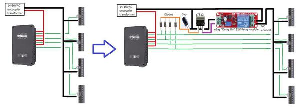
Many alternatives of course, but here's what I was thinking.


aiu ucs widget

As i understand it, your situation is as shown on left.  A TIU switches AC power to individual UCS - 4 shown but I realize you have more.


So on the right, suppose you put a diode on each line to the UCS.  If ANY UCS is activated, it charges up a cap and 7812 voltage regulator IC to generate 12V DC.  The 12V DC is applied to a eBay "delay-on" relay module (has 10 Amp contacts).  When 12V is applied to the module, it waits up to 10 seconds (screwdriver adjustment) and then turns on its relay (hence the name "delay on").  When the relay turns in, it cuts the Ground power to all the UCS....and keeps power cut until the TIU turns off the UCS.


The "trick" is that you need to be able to break the common to the UCS as shown.  This may require an isolated Accessory transformer if the common of each UCS coil is tied internally to the outer rail.


Obviously I have not tested this is and simply offer it for discussion. The relay module is less than $2 (free shipping), for example:


http://www.ebay.com/itm/371194...194142587%26_rdc%3D1


The relay module even has 2 on-board LEDs, one of which turns on when the relay is on...so that could serve as a "fault" indicator.


The diodes, cap, 7812 regulator IC are generic components and would be maybe $1-2 total on eBay.

Attachments

Images (1)
  • aiu ucs widget

Barry, you've got it backwards.  It wouldn't be an issue if the grandkids would better train RJR.  Seriously, though, a wise professor once drilled into a class I intended:  "Gentlemen, if something can possibly happen, sooner or later it shall."  At this time, I have no uncouplers connected to the AIU


Stan:  Interesting.  I went to the link your posted. Unbelieveably cheap!  How can you be sure just what that gizwack does?  I note there are similar items at the bottom of the page, some of which are the same thing without shipping.


The coil commons are internally connected to the outside rail.


But you did give me an idea.  Hot lead to the magnet and one control rail is through UCS terminal 2 (varies on other uncloupling tracks).  I can connect a diode to each such terminal, connect the other ends of all the diodes together, add an electrolyic capacitor to smooth the half-wave DC pulses, and fee the output into a device such as you picture, connecting it to blow a horn when it pulls in.  The reason for the diodes, in addition to providing DC, is to preclude the #2 terminal of all UCS tracks being activated when one button is pressed.

I found cheap relays on line at 99 cents each, 12VDC, at www.jameco.com, and bought a few dozen.  I see they still have similar relays, but they're now $1.09.


Stan, I found the following description for this item in a lot of 5 for $8.19 from aliexpress:


 Switch on the power relay with 1-10S fixed period suction close and disconnect. Specific for: to relay for 12V power supply, relay will soon suction and relay output of the state for: normally open and public conduction, normally closed and public off; Until the time delay 1-10S (regulation), relay release, at this point, the relay output of the state for: normally open and public disconnect, normally closed and public conduction; As long as the module uninterruptable power, the state will always keep to 1-10S fixed period suction together and release

Can you translate?


Added:


Unbelievable!  At the bottom of one of the links are 12VDC SPDT relays for 44.9 CENTS each.


Last edited by RJR
Originally Posted by RJR:


Stan:  Interesting.  I went to the link your posted. Unbelieveably cheap!  How can you be sure just what that gizwack does?  ...


The coil commons are internally connected to the outside rail.


Well, there are only 2-terminals going into the gizwack.  This is power.  If you think about it, what else can it do?  So you apply power and is either turns on the relay for 1-10 seconds and then turns the relay off (so-called "delay off")....or keeps the relay off for 1-10 seconds and then turns the relay on (so-called "delay on").  I believe it is the latter.  But either way it would serve the intended purpose.  That is, you simply use the NO or NC contact to switch the ground/common wire to the UCS depending on whether it's a delay-off or delay-on module.


OK, so if the coil commons are "hard-wired" to track-outer-rail, then you'd need a separate (isolated) transformer to supply UCS power.  Note that this transformer could be DC output if such a transformer/adapter had sufficient voltage/current to drive a UCS.


BUT WAIT!  There's more!


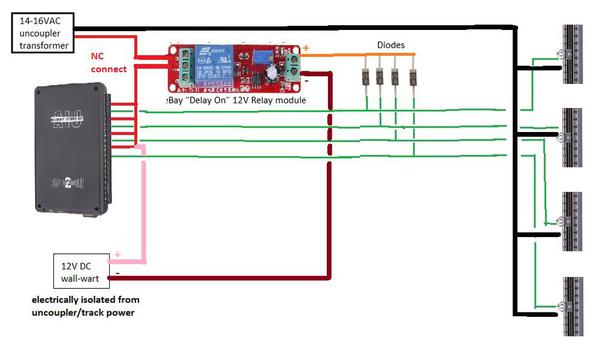
So if you don't have a spare isolated power source with suitable horsepower to drive the UCS, here's an alternative version.

 aiu ucs widget alternate

First you have to be a believer or convert to the religion of electrical isolation.  So let's say you have a 12V DC wall-wart or another source of isolated 12V DC.  You can buy 12V DC regulated wall-warts on eBay for about $2...or you might have one already from a cell-phone charger or whatever.


You connect the 12V DC "+" as shown in pink so that it rides on the TIU/AIU switched common.  You still have the diodes.  Now, when any UCS is activated 12V is ALSO switched to the eBay relay module.  After its 1-10 sec adjustable delay, the relay activates and cuts off UCS power.  The TIU/AIU is still driving whatever UCS is active so the pink 12V DC still goes thru to keep the relay module activated (and cutting off UCS hot power).


If you follow all this, you will note that by clever connection of the 12V DC "+", you can use the eBay relay module output to power a 12V DC alarm, light, horn, whatever.  That is, when the relay activates to cut UCS power, you can configure the relay to simultaneous apply power to the alarm device.  You may need to stare at this for a while but I think it will work.


Originally Posted by RJR:

 Switch on the power relay with 1-10S fixed period suction close and disconnect. Specific for: to relay for 12V power supply, relay will soon suction and relay output of the state for: normally open and public conduction, normally closed and public off; Until the time delay 1-10S (regulation), relay release, at this point, the relay output of the state for: normally open and public disconnect, normally closed and public conduction; As long as the module uninterruptable power, the state will always keep to 1-10S fixed period suction together and release


Can you translate?


No, I can not.  I've seen some pretty bad translations from these Asia eBay modules and this may be the worst ever!  They keep talking about suction so all I can say is that it sucks.


So if you happen to have a 12V DC wall wart lying around, I figure you're down to about $2.  Do I need to try harder?!


Attachments

Images (1)
  • aiu ucs widget alternate

I've seen some pretty bad translations from these Asia eBay modules

You think that's a translation? 


I found an interesting gizmo to go with the gizwack.  The URL is long, so instead of posting it, go to www.aliexpress.com and search for:

F08405 Current Detection Sensor 0-20A AC Short Circuit Protection Switch[China (Mainland))

F08405 Current Detection Sensor 0-20A AC Short Circuit Protection Switch


I may get one just to explore it further.  Its relay requires 24VDC, which is available.  May also have a use as an electromagnetic circuit breaker.


A wall wart capable of putting out 2.7 amps is rather rare.

Originally Posted by RJR:
A wall wart capable of putting out 2.7 amps is rather rare.

Are we talking about the 12V DC wall-wart in the latter example?  As shown, that wall wart only needs to power the eBay module so it needs to be maybe 100 mA.   Presumably you already have a suitable source capable of driving a UCS at the several Amps.


Where are you going with the current transformer module?  As I understand it, that module activates its relay when the sensed current exceed some settable threshold.  But for the UCS application, it seems setting the current threshold is irrelevant.  That is, if ANY current flows thru the "hot" wire feeding the AIU, then that means one (or more) of the UCS has been activated and that's all you need to know to trigger the 10 sec timer.


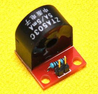
That said, on eBay for less than $2 free shipping, here's a bare bones 5A current transformer on a tiny module.  This would generate sufficient current/voltage at its output to trigger most any eBay timer module.


ct 1000x 5A

http://www.ebay.com/itm/DIY-5A...;hash=item58b9e0f5b0


Attachments

Images (1)
  • ct 1000x 5A

There are plenty of sources for individual relays on the cheap.  The $20 for 16 "deal" is due to each relay being capable of taking logic level, logic current, and being opto-isolated already.  Having screw terminals is a nice plus.  I chose this based on using a cheap micro-controler to do most of the work.  


http://www.amazon.com/SainSmar...words=16+relay+board

These can be found under $20 on the auction site.  ( they come in 5V or 12V coils on the relays.)

Last edited by JohnGaltLine

Stan, I misunderstood the functioning of the wallwart.


As to the current sensor:  I have a small control panel with buttons for all the uncoupling tracks, fed from a power source.  If no button is pressed, no current is drawn.  If one uses a current-detecting sensor on that feed, one does not have to attach a connection to each UCS.  Having the detector trigger some warning, either immediately or after a prescribed time, either auditory or visual, would be simple but effective----I think..


John, when you start talking logic currents and opto-isolation, you're over my head.  Electric I'm fine with; heavy electronics, I'm not.  But thanks for the link to those relay boards.  I could have used them a few months ago when I modified a postwar Lionel gantry crane to move along a track, with the panel to crane feeds being very low amperage 12VDC, a neeed to move only one switch for any function, rather than 2 for some functions, and a time delay to eliminate the crane rotation that results if you release the clutch solenoid before the motor has stopped spinning.  I have designed, but not yet fabricated, circuitry to permit operation from the AIU.  I will use similar 12VDC relays to control other accessories from the AIU, since I can use 24 or 26 gauge wire.


All it takes is time.


Revision:  Review of customer comments indicates that those boards may be more complex than I thought.

Last edited by RJR

it's not as complex as it sounds.  Just means you can power these relays right from a computer port, or microprocessor without needing to add all the little parts like transistors and back-spike diodes and such.  Opto-isolators are simple in concept as well.  the input turns on a light, and a light sensor then turns on the relay, this prevents the possibility of damaging electronics from any sort of relay failure or more commonly from spikes caused by the current draw of the relays.   all in all these boards are specifically made for folks that have no need to understand how they work, just that they do.  


in any case, that plus a $10 arduino and a couple dollars of other components will give you 16 relays that you can make do just about anything you can think of.  

Originally Posted by RJR:

As to the current sensor:  I have a small control panel with buttons for all the uncoupling tracks, fed from a power source.  If no button is pressed, no current is drawn.  If one uses a current-detecting sensor on that feed, one does not have to attach a connection to each UCS.  Having the detector trigger some warning, either immediately or after a prescribed time, either auditory or visual, would be simple but effective----I think.

I get what you're saying - making a new connection to each UCS line with a diode can be a bother.  But if you're wiring up all the UCS lines to the AIU anyway, you could add the diodes right at the AIU.  I don't know if you're an advocate of terminal blocks/strips external to the AIU or, if not, there have been many OGR demonstrations of how to make 2 connections into each AIU terminal - which of course is what you need to do with the UCS "hot" power to daisy-chain it to each AIU port.


Note that with the diode method, you can still use your manual UCS control panel so that you use either the DCS remote or the existing panel buttons.  That is, if you wire each panel push-button across the respective AIU terminals, the timer circuit will also detect a push-button held down for more than 10 sec and cut UCS power (and activate power to a 12V-powered audible/visual alarm if desired).


The "trick" to using an independent/isolated 12V supply plus diodes is it allows sensing when any AIU port is active for more than 10 sec even after the UCS power has been cut.  That's because the 12V power is still flowing thru the AIU port to hold or latch the fault condition.  If you only use the current-sensor detector, when you cut UCS power then no current flows thru the AIU port and you can't detect when the fault condition clears.  Well, I suppose you could concoct some scheme where rather than cutting off all current to the UCS during fault you could throttle it back to, say, 0.1 Amp or something benign that wouldn't fire the UCS and wouldn't waste too much power but enough to be detected by some current sensor widget.  Then when that minimal holding current finally disappears (user turns off the AIU port) the circuit resets.

Stan:  I would feed the AIU and the uncoupler control panel from the same lead.  The feed to AIU relays would only serve those that are controlling intermittent only accessories.  I could wire the current sensor to turn on a light whenever current flowed, or use a time delay relay fed from it to blow a horn, light a lamp, blow a siren, etc after a period had elapsed.


John, I have never delved into the mysteries of arduino, and since I'm low on RAMM*, I don't know if I want to start the learning process.  Funny thing about retirement, is that it leaves less time to do things like go out on the boat or use a train layout.


*RAMM=random access mental memory

So what is the plan?  Are you using a current sensor module?  etc.


The module you received appears to be identical to the eBay version.  In which case, apply +12V DC to the 2-pin connector (VCC="+"  GND = "-").  The LED labeled "POWER" should come on.  After 1-10 sec adjustable by blue trimpot, the relay will turn ON and you'll hear the click; I believe the 2nd LED will also turn on at that time. 


It's an SPDT relay with the 3 contacts on the 3-pin connector.  Common is undoubtedly in the middle.  For whatever reason they don't use the familiar Normally Open (NO) and Normally Close (NC) labels like on train accessories but should be easy to decipher by experimentation or a meter if you have one.

Susan, this was not to guard against faults, but to guard against burning out uncoupling magnets if using the ACC circuits to activate and the wrong remote button should be pressed. 


I have a current detector module on order, which I'm not sure will work.  Unfortunately it needs 24VDC power, which is not readily at hand on my layout, but casn be provided.


While it is quite feasible for me to make a circuit that will cut the power to the uncoupler while keeping the power cutter activated, it's simpler to just have some audible, loud alarm if power stays on for over, say, 10 seconds.  By putting a current detector in the general feed to the AIU ACC terminals that are used for the uncouplers, no need to put some device for each uncoupler.  Having had push buttons fail, the same system could be used for an uncoiupler control panel.

Last edited by RJR

Add Reply

Post
The DCS Forum is sponsored by

OGR Publishing, Inc., 1310 Eastside Centre Ct, Suite 6, Mountain Home, AR 72653
800-980-OGRR (6477)
www.ogaugerr.com

×
×
×
×
Link copied to your clipboard.
×
×