
I am currently building a layout that will have DCS, TMCC, and Conventional power on  all tracks. Today I am looking for opinions regarding how to toggle switch power to a passing / siding track, that is off the mainline and located 20'-30' from the TIU/Transformer/ toggle switch, location. If I was wiring conventional only, I would simply use #2 Below. However, with a TMCC and DCS signal what would be most appropriate approach. I will have many similar arrangements.
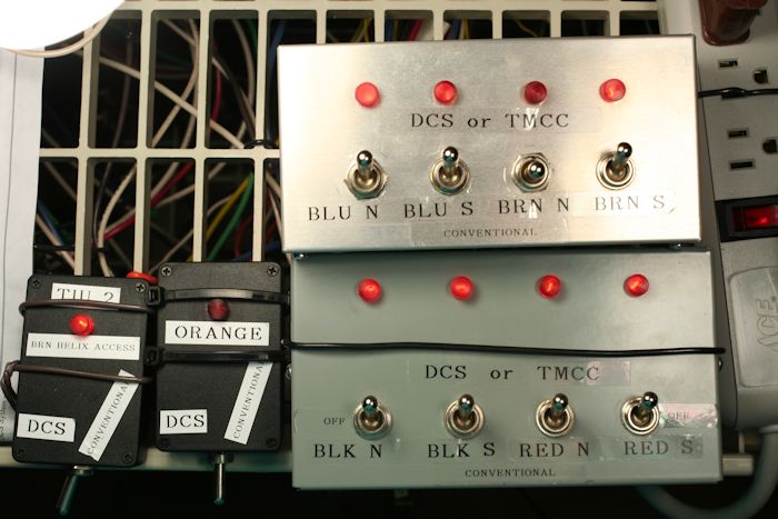
1  from TIU output switch both HOT and NEUTRAL with DPST and from toggle and controls to the passing siding 20-30' away
2 from the TIU output take a toggle switched HOT only to the passing siding, and make/connect passing siding Neutral to mainline Neutral
3 from the TIU output take a toggle switched Neutral only, to the passing siding, and make/connect passing siding HOT to mainline HOT
4 some other variation?
Thank you for any input
kevin
Original Post

Replies sorted oldest to newest

If your using some sort of paired wiring such a speaker wire out to the siding. I would run your wiring off your TIU to a terminal strip. You will end up using I’m sure a few tracks off that 1 channel.  Run your paired wire from the strip to the track itself. Put the strip close by to all the tracks it will power up. Put a split in the paired wire and separate it for about 4 inches. Cut the wire going to the center rail and put connectors to attach them to the relay or solder them on. Put the relay as close as you can to where the toggle switch will reside. I use automotive ones that have a mounting tab.  Bosch lookalikes.  Connect the 2 wires to the relays outputs. The common and the one that turns on when the coil is powered. Should be a schematic on the side of it. Now run the wires from the toggle switch to the relays coil to control it.
You will need a 12v dc power supply but it will come in handy for other things on the layout.

The benefit is the toggle doesn’t have to carry the DCS signal and you should end up with a shorter wire run to the track.  You can get by with small toggles and wiring to control the relays coil.

Last edited by Dave_C

gunrunnerjohn

Hi John,

I also will be using your "Watchdog Generator" I am curious about your "yard Panel".  Is the assembly off the shelf or did you build it? Are you switching both the neutral and hot or just one and then going to the yard? Can the lighted buttons be lighted with an external source (14vac) other than track power as sometimes I will be using a Z4000 in conventional and I would want the lights to be, on even if transformer handle is at zero volts at other times the track power will be using (18vac) with a TMCC & DCS signal

Would you mind sharing a source for your lighted on/off buttons. I am trying to switch 18 isolated tracks on/off

Thank you again, your expertise is a great help

kevin

Kevin,

I built the switch panel.  I used a cable feed-thru for desktops for the outside, the actual inside panel is 1/16" fiberglass sheet, and the switches are lighted toggles.  The LED's are totally isolated, so you can use any power source for them, it doesn't have to be track power.  I had the lighted buttons in my switch box, but I don't have the exact source handy, they've been there for some time.  However, there are plenty of lighted switch buttons.  FWIW, don't get hung up on having to have 10A switches for a single yard track, you'll greatly limit your choices.  You're not going to be pulling that kind of power on a single yard track, so if you find lower rated switches, I'm sure you'll be fine.

@Fast Mail.....

To add a bit of variety to this discussion (and maybe to give you more to think about), I used a more complex approach.

I strictly use Command Control (a combination of MTH DCS and TMCC) on my layout.

Implementing the DCS portion involves some stricter wiring configuration rules; especially in regard to wire lengths used to feed  track power blocks from power distribution points (DCS recommends the use of a "star wiring" configuration).

Any way....to adhere to those wiring rules (restrictions?), the toggle switches on my  control panel do not switch actual track power, but switch (turn on/off) relays that turn on/off the track power. That way, the power wire from the distribution point to the track block is a direct route without having to double back to a toggle switch at the control panel.

Just something to think about.

@Junior posted:

@Fast Mail.....

To add a bit of variety to this discussion (and maybe to give you more to think about), I used a more complex approach.

I strictly use Command Control (a combination of MTH DCS and TMCC) on my layout.

Implementing the DCS portion involves some stricter wiring configuration rules; especially in regard to wire lengths used to feed  track power blocks from power distribution points (DCS recommends the use of a "star wiring" configuration).

Any way....to adhere to those wiring rules (restrictions?), the toggle switches on my  control panel do not switch actual track power, but switch (turn on/off) relays that turn on/off the track power. That way, the power wire from the distribution point to the track block is a direct route without having to double back to a toggle switch at the control panel.

Just something to think about.

DCS you have to send a watchdog signal so engines do not start up.

So you either have to use a TIU channel for the siding, such that when your power the siding, the TIU channel is sending the watchdog.

Another option is the use of a IR DCS commander, with the barking watchdog reset board.

FWIW, I do not agree, the strict rule of star wiring is not an absolute requirement. Yes, good if you can follow it, not saying it's bad, but it's not set in stone and nothing else works.

@Junior posted:
Any way....to adhere to those wiring rules (restrictions?), the toggle switches on my  control panel do not switch actual track power, but switch (turn on/off) relays that turn on/off the track power. That way, the power wire from the distribution point to the track block is a direct route without having to double back to a toggle switch at the control panel.

I have some sidings and secondary loops that have relay controlled power switching for the same reason, I didn't want to have power making a round trip for no reason.  However, my 10-track yard has the power coming into the switch panel and then distributed to the ten tracks that are right next to the switch panel, hence no reason to go to the trouble of relays.

Sorry, was reading from the bottom up and replying to the previous reply. I see much of what I said was already considered.

Thanks again to @gunrunnerjohn for the development of the barking watchdog generator.

While I turned it into an easy to build board, the a big chunk of the thanks should go to @stan2004 for the initial design and idea.

gunrunnerjohn , Junior

Thank you, for your comments and expertise. I was considering the use of relays but until I investigated the cost and construction, I thought I was overcomplicating things. I will have as many as 22 switched tracks more than 25' from controls.

Last night I found the relay below (all electronic, two tracks per module for $13.50). on AMZon) This option seems became reasonable considering I have a leftover spool of 400' of 22-gauge 8 conductor in the garage against the cost of 14-2 and 16-2 plenum rated. Also, the fact that John suggests switching only the HOT (center rail) while using a DCS and TMCC signal.

I am curious what relays you guys have used and are you satisfied?  and what control voltage as well as source of control voltage


41hjGLoHz-L._AC_61xXeTPswIL._AC_SL1000_

Attachments

Images (2)
  • 61xXeTPswIL._AC_SL1000_
  • 41hjGLoHz-L._AC_

Kevin....

I used 12vDC relays that I bought from China. If you're willing to wait a bit, you can save quite a bit of $$$.

Or you can purchase/use what you've already found for those circuits you want up and running right away and order/use relays from China for  those that can wait.

Also of note, the relays I use plug into sockets. That way if a relay gets damaged you unplug that bad one and plug in a new one.

Polish_20221216_110633620

I took a 2nd look at your schematics and it appears your relay solution has bridge rectifier built into them? If that's the case, your wiring these relays would definitely be simplified; running AC to the relays directly rather than having to provide a 12vDC power source.

Funny story......my layout is broken up into power blocks that feed track blocks. Each power block is switched via relays. That way I can turn off any section of my layout. I initially bought a 2A 12vDC power supply to drive 26 relays. After everything was connected, I was happily running trains without any issues.

Later I wanted to do an "Engine Add" to the DCS system. So I started switching off track/power blocks so that only one track block was powered. But as I switched track blocks off (meaning relay coils were being energized), other track blocks that were previously switched off were coming back on! Whaaaaa?

After much research and testing and troubleshooting, I discovered the 2A power supply was not large enough to energize all the relay coils at one time! As I switched off section by section of my layout (energizing coils), the power supply would get maxed out and couldn't support relay coils previously energized.

I now use a 10A 12vDC power supply to support all those relays.

Attachments

Images (1)
  • Polish_20221216_110633620
Last edited by Junior

Add Reply

Post

OGR Publishing, Inc., 1310 Eastside Centre Ct, Suite 6, Mountain Home, AR 72653
800-980-OGRR (6477)
www.ogaugerr.com

×
×
×
×
Link copied to your clipboard.
×
×