


Thanks for putting that up there for me to see that, thats exactly what i needed to see and realize. I am definately going all Ross on this layout but if i ever had to use some ross flex at least i know how close they look as far as color and all that and after doing some ballasting and things im sure it just blends in. I have read some of your other threads on gaps like that with the track, i used to be real worried about any gaps but realized after reading things on here as to why the pin stops are there and why its good to have a small little gap for thermal expansion/moisture differences in the winter/summer that it needs room to expand and contract. Also you get that neat clickity clack i believe as well which thats something i want to hear. After doubledaz and turkey_hollow_rr and other folks on here did some comparisons on track and noticing the differences they all seem to have something unique and cool about one over another but the good thing is between the brands cant go wrong and even atlas i have considered but settled on ross as my final decision since from the postings and what i have seen atlas switches are hard to get especially with supply chain shortages im sure. But i know for sure i will be happy with this and if it wasn't for all that have contributed to this forum i wouldn't have made some expensive mistakes. Its one thing to make a mistake and learn from it and correct it, but another when you put out hundreds of dollars on things and have to trash it all and buy it all again thats what i dont want to do because then i look at it as well i could have used that money to buy a nice locomotive, more track , scenary, a building or something lol. But i know sometimes you will have mistakes that cost but if i can avoid them awesome. My goal is here to learn from everyone, i am learning scarm and anyrail at the same time but i think im going to convert to scarm the biggest thing is for cutting straight sections thats a big deal for me now and also i notice alot of folks prefer it and i like it too just a bit harder to use. Once i learn and become efficient at this , my contribution is to also help someone else just like me in these forums where i was at today so others can enjoy this hobby so right now i may be taking help but at some point i will be offering help as well so this forum can continue to thrive and get more people involved into model railroading. I also want to see younger people getting involved more too because i think that the "computer age" while it has helped us alot, it also is taking away from the hey lets get out a board game or family time or run some trains and build together as a family so your involved with others and not isolated to a phone or ipad. I am trying to push this concept in my home now so my kids can learn to appreciate this hobby and others. I think its healthy to take a step back from the digital age and do things like this. I want the generational hand down to keep going with this hobby so that it just doesn't get put on a back burner for an ipad or computer theres just so many things to appreciate about this hobby.
Here's a better shot of some the newer Gargraves and the end of a Ross switch. The colors are a bit closer. The gaps you see here are because that line between the sections is a power lift bridge, to that track on the right comes up over two feet to allow me to walk under to the inside of the layout.

Truthfully, unless you're really looking for it, a couple feet away you usually don't even notice the color variations.
Attachments
Images (1)

Ah you just peaked my interest here with that power lift bridge, so i have a use case right now on my layout where i have a fold down piano hinge piece of plywood with a latch on the right side of my layout which allows me into the space. I plan to have straight track across there but i have the issue where i need to figure out how to have a drop down piece of track that goes back into place once the plywood is latched back into its normal position. I have been doing research and looking at all the different ideas but the one thing that stumbles me is ok how far away or how close to but the tracks together on each side so i can let the plywood drop down and go back into place without breaking anything and not having too much of a gap that it derails something. Its also on my big outside loop and inside loop which means theres no way around it unless i decide to make it a fixed plywood door or something and just duck under
Well i just purchased scarm so now i have both anyrail and scarm to play with, i actually am starting to like scarm more i mean i like it all but at least i have choices now to use to model things im going to play around with it and i see alot of youtube video tutorials out there on how to do things im going to start watching some videos and training myself on this so i know it more. One thing i been wondering if your doing any elevations in scarm and you get the 2.5% grades and all that like we looked at before, not that i am going to do that for this layout but i just wondering how do you take the elevations from the scarm drawing you do IE translate it from paper to the benchwork? Thats one thing i think i should learn at some point is how to take whats on paper for elevations and make them. Like where to start, how tall of a piece of plywood/board do i need and how much bigger does each board need to be as it elevates etc to achieve the grade that its suppose to be and all that stuff
Also i noticed my paypal said that its milen is the owner of scarm its amazing you even know that person to influence scarm updates/changes thats actually kinda cool!
My benchwork started out as Mianne benchwork and then it was "embellished". This is the Mianne power Lift-Bridge, it's the largest size they offered, 4 feet wide by 4 feet deep.


This is my whole layout build thread, if you need something to put you to sleep. ![]()
New Train Room Finally Getting A Layout!
Attachments
Images (2)
Milen actually beta tested the early versions of his software by giving it away on this and other foras. He still maintains a thread on this forum to announce product updates and new features. For what you are building, you probably could have used the current free version (limited to 100 pieces of track), but I'm always happy to see a model railroad vendor get rewarded for his work.
You mentioned that there is some room between your table edge and surrounding wall. While that may eliminate any scraping or gouging caused by larger engines, it raises another issue to consider. If one of your big engines derails at a point where there is too little table space to "catch" it, it will go to the floor and may be severely damaged. Such a fall will not be covered by your homeowner's insurance, so leave a good 4 or 5 inches of space outside your outer most loop in an effort to minimize the likelihood of such an accident. The other alternative is to attach a raised lip, probably about 2 or 3 inches up, all around your table to protect your equipment from such a fall.
Chuck
The trick to a flip up is to have the hinge above the rail, obviously, a flip down needs the hinge below. I shoot for the width of a saw blade for track cuts along seams.
I believe John has a Mianne lift. I built a DIY version.

I also overlap the table a bit, hopefully scenery will help hide the seams some more. If you look close here, these are different cuts of Atlas "placed" next to GG flex on the top route and atlas next to another Ross switch.

Attachments
Images (2)

Wow yeah so i wanted mianne benchwork as my first choice but the guy never responded to me or was very sporadic he wouldn’t return calls and then he would reply to emails then when i got him on the phone he would say yeah i’ll have it to you tomorrow my bench work plan but every few days i called i got the same story i think he’s overwhelmed with work but his product is solid and i wanted his benchwork but since he never replied o ended up with sievers which it’s very good as well maybe i can find that power lift section on his website to order
Dave, there are all kinds of techniques for building grades. You’ve used the trestle sets, but they’re designed for grades around 5%. Woodland Scenics sells readymade 2%, 3% and 4% foam Incline Kits than can be shimmed for other grades. Google “cookie cutter benchwork” and you’ll get examples of all kinds of methods used.
Thanks for the tip, so far with the layout the track total in materials is around $2525 which is about where i thought it would be thats just estimating the track only on ross's website and i will probably order some extra pieces in case i make a mistake, break one all that good stuff. I will check out the cookie cutter stuff see what i can find, now that i have seen scarm and purchased it i am having fun with it, i actually prefer it over anyrail i been playing around with it and see why scarm is preferred and it does things anyrail just doesn't do
Risers are probably the only thing I really lean on software to help with. Find a few strategic points along the way and cut as close as I can to the heights in AnyRail given from the slopes. The tops of the risers are cut at about 1.5 degrees.

Attachments
Images (1)
Dave,
Dan's photo is an excellent example. It shows both tabletop decking and open framing with cookie cutter sub-roadbed on risers. He has attached his risers to the top of the framing using pocket holes and some of the riser are notched at the bottom with part sitting on the decking and part on the framing. You already have a full tabletop, so your risers would sit on the tabletop just like the trestle set supports you had with the FasTrack. Instead of the track sitting directly on the supports though, you'd add sub-roadbed like Dan's and the risers would support that. I don't show it, but on top of the plywood sub-roadbed would be whatever roadbed you choose (cork, foam, Ross, etc.) and then the track.

Here's a closeup the support. Note the 3% angle on the topper.

3D view.

Here are the heights at the track joints. They can be used to guesstimate how many risers you need and where to place them. Since folks tend to build framing with 16" centers, placing risers every 16" or so seems reasonable, but that depends on the thickness of the sub-roadbed and the weight of the engines you plan to run. One thing to think about is the easements going into and coming out of the rise. You don't want to immediately go from 0" to a 3% rise with your first support. Here, too, the length and degree of easement depends on the engines you run and how far out the cowcatcher sticks. If you rise or drop too quickly, the cowcatcher will hit the rails.

Just a 3D view with a 3" rise over the entry. A 3" rise gives you a 3.1% grade.

Attachments
Images (5)
Files (2)
Dave DoubleDAZ I should have explained that the little 1/2" pieces on some of the risers were added when I decide to make the upper level 10" instead of 9". I added 1/2 on some risers and extended the transition to level on the upper level to get the additional inch. Not that the risers can't be built that way.
One thing to keep in mind when going from software to reality with grades is that in software all of the measurements are relative to the top of the rail. That is the zero reference and it is really 1 7/16" higher than the framing in my case. (Plywood, homasote, roadbed and track.) You just have to remember when you go up X inches there is some structure below that, but the height dimension in software will still give the proper cuts. If the software said that point in the curve needs to be at 7", that's what I cut the riser to. If there is plywood and homasote on the framing below that point I have to compensate for that to keep the reference correct. This case is a little easier since all of the surface is in place. You just need to account for roadbed and track. I don't see any overhead crossings in Dave's design but if there ever are it is really important to understand this so you have enough overhead clearance.
Dan, got it. That explains why it looks like there's a notch in some of the risers. Good points about the clearance. In this case, there are no overpasses, but I did put together a version where I swapped the Blue and Orange tracks on the right side to create 2 overpasses. Since Dave already has a full tabletop and rigid foam sheets come in 1" and 2" thickness, I raised the whole layout 4", then added a 3.5" downgrade to the Orange loop and a 3.5" upgrade to the Blue loop, a total of 7". Those result in grades of 3.7%, not ideal, but doable with modern engines.


Attachments
Images (2)
Dave, you're probably going to ask for it ![]() , so here's the file with the grades. The deck is on a separate layer, so turn that off/on in the Layers box to edit the tracks, otherwise you won't be able to see the tracks.
, so here's the file with the grades. The deck is on a separate layer, so turn that off/on in the Layers box to edit the tracks, otherwise you won't be able to see the tracks.
Attachments
Files (1)
@DoubleDAZ Nice update to the track plan.
I understood Dave to want to run large engines so he needed 072 for at least one loop. Right now it looks to me like he has no place to park an engine and cars. His room should have space for a narrow dead end "shelf" which could come off the upper track to the right of the entry keyhole - which I think is a solid wall.
All - regarding the risers - I've taken this approach on my layout and even went to the extent that I precut my risers with the slope on one end and flat on the other. I only did this because I did not know any better and I already had a plywood deck in place. This worked fine for the install, but as time went on I needed to make changes and the (cheap) 1/2 ply I used warped in places. (Supports were 12 to 16 on center and it still warped screwed down.) This made making adjustments really hard, one because I had already installed hardscape and two I had no access from below. When I do this again, I would use Wescott's method of attaching risers to the bench work and not a plywood deck. But given what Dave is trying to do, the approach suggested will work fine, provided he puts in enough large holes (hand sized) in the deck for wiring of track, switches and other goodies. Cutting holes in my underlying plywood deck has created nothing but headaches as the vibration causes all kinds of things to loosen and move around. Adding switches or signals later is not fun.
As far as the transitions to a new grade, I found cutting a section of plywood long enough to to start the transition and get into the grade was critical for smooth operation. (Wescott uses the cookie-cutter term for this.) The plywood is going to have to bend into an "s" shape - which it will not want to do. However for our purposes that is a good thing.
So don't use cheap plywood. All of my framing, lift table, and legs are made of 3/4 and 1/2 arctic birch plywood.

Attachments
Images (1)
Okay Jeff, you have gotten my curiosity up. How are you going to bend plywood into an S curve?
Enjoy reading this discussion. We are all Ross and use RRTrax which has been accurate to within 1/4” and is usually dead-on. As someone suggested earlier, after measuring carefully and going thru the gyrations, we found that dry fitting and winging it works pretty good. As you gain experience, it gets fairly easy.
Ross doesn’t make flex track. Steve sell Gargraves, track screws, cork, etc and has been great to work with. We are on level 2 and have installed 40+ Ross turnouts. If you are going to have a large number, you might want to do the soldering yourself if you are good at soldering and save the $$$.
Good luck.
@ScoutingDad posted:@DoubleDAZ Nice update to the track plan.
I understood Dave to want to run large engines so he needed 072 for at least one loop. Right now it looks to me like he has no place to park an engine and cars. His room should have space for a narrow dead end "shelf" which could come off the upper track to the right of the entry keyhole - which I think is a solid wall.
Dad, if you look back a couple of days (post #34?), you'll see I posted a photo with a switch in the upper right corner going to the right. I couldn't tell from the photos that have been posted what was to the right of the layout, so I ended the spur at the end of the table.
However, there are problems with adding a switch to any of the corners. Dave doesn't like the idea of running large engines through the curved part of switches, and I agree with him as a general rule. However, I'm not sure how big a deal that is with O-72 switches at reasonable speeds.
In any event, Dave then he goes on the suggest a future expansion into the room on the left which would require switches in the corners. I'm not exactly sure what he has in mind, so I drew up a plan with a loop of O-72 tracks going into that room as well as a spur onto a shelf in the upper right, assuming I understood what you're suggesting. He also suggests he may want to elevate sections of Blue loop on the right and I've posted suggestions for how to do that.
So, assuming he doesn't want to add the shelf to the upper right, my "idea" for parking large engines is to park them on the Red tracks. Both are 50" in length and should hold at least 1 engine each allowing 3 large engines to remain on the layout. Rolling stock and smaller engines would be stored on the Green tracks. When he wants to run a smaller engine around the outside, the Blue track on the left would become a passing siding. He'd move the large engines to the passing siding and run the smaller engine around the Blue/Red/Orange loop. I realize that's not ideal, but little is when trying to cram so much with special requirements into a relatively small space.
Bear in mind, these are just my thoughts on how to make things work. I don't advocate any particular way to do things.

Attachments
Images (1)


@DoubleDAZ @Bill Webb I love this forum - great comments and thoughts.
Bill - the second article I started to write addressed this. However since that is not going to happen, Westcott's book on page 10 has 2 photos on how this happens/works. (no photos - copyright) Plywood is resistant to sharp bending so for our purposes this works to our advantage. If we were going up the lower section is firmly secured to a base. Then we start bending an upwards curve, then we insert a support and then bend the plywood back down. This forms an "s". This is the only place where cheap 1/2 plywood works, since it bends easier. BUT - if bent too much, the transitions will be too steep and the bigger engines will not be happy. Think about when you cut a plywood sheet on sawhorses - the unsupported section will bend by itself. I'll have to measure mine, but I think I was getting about a 1/2 inch rise over 24 inches ( roughly 2% ). I do not think you can get that degree of bend out of a 3/4 sheet, especially baltic birch type. Of course that is a good thing if you are trying to run scale wheel sets.
DDaz - I spent a few hours mulling the layout a couple of days ago. I did not think there was really enough room for a rising section without getting too steep (for me its 2.8 max, 2% or less ideally). Missed the extension from your earlier post, but that is what I was thinking. I also thought there was an exterior window where the blue extension is shown. I do not have any problems running any of my engines through an 072 or greater turnout. But generally I agree with staying away from designing using the turnout as normal operation. Of course then there are the ROSS curved turnouts, which for me have worked great in my tight layout.
I also agree with the comment - don't use cheap 3 ply 1/2 inch plywood. It will work for a while and then become the source of operating issues. I have learned my lesson from trying to go cheap.
Jeff
Jeff, I don’t advocate what I show in the photo, just wanted Dave to see there are options depending on what he wants. My biggest point though was that if he were thinking about what I show, he needs to think now because now would be the time to raise the height rather than have to tear up ALL the tracks to do something like that later. I believe he mentioned putting in the switches for a potential future run into the other room and that would be smart if he’s really serious about doing that. My only concern there is I don’t know what’s on the other side and how O-72 curves would fit. I thought about the window using 2 switches with a Sri siding there instead of the switches in the corners. Here’s what that would look like.

Attachments
Images (1)
This is interesting and thanks everyone for the tips here on elevations but the hole in the wall scenario would be through the top of the drawing in the left corner area, the next room goes through the top wall. The left goes through my window/outside and the right goes into hallway area, its open area but not much room to spare. If you look at the fast track pictures i had earlier on the posts you will see what i mean. Below the lay out on the bottom is an open stairwell/split foyer, i could go past that railing there if i took something and built that up some how
Ah, totally missed that. I was wondering why there’d be a window to another room there. Not knowing how much room is on the other side, here's what that might look like.

Attachments
Images (1)

Files (1)
This is what I was considering after I gave up on connecting track. Individual loops but different elevations. Left corner is supposed to be a hill. I would probably move the inner loop to give a foot or so (from what would be walls or rock face) to give space for buildings / small town and road. I thought the inner oval would be really boring, hence the turnout and 30 degree crossover into the "yard".
Instead of the 072 turnouts, people use Ross #4s (?) for switching to different track?
Anyway just ideas to mull over and discuss, as Dave said, I am not advocating anything - Just trying to see what might work and what are not so good ideas. This is a tight space to work with.
Attachments
Images (1)

@ScoutingDad posted:Instead of the 072 turnouts, people use Ross #4s (?) for switching to different track?
If you're asking the question, here's part of the reason why. Even if you aren't, others might wonder. ![]()
- With #4 and 11° switches you get closer spurs using the TR series of sectional transition tracks without cutting wide curved sectional tracks.
- See what happens with the O-42 switch since Steve deleted the O42P parallel transition track.
- Note the smoothness of the 11° and #4 turnout sections compared to the others. That allows for higher speeds and smoother operation. I believe the general rule is 11° switches for yards because speeds are slower and #4 switches for mainline spurs because trains °are still passing at speed, though I think most folks like 4.5" or more of clearance.
Of course, different brands offer different options. Atlas uses a #5 with a 1/2 O-72 and a #7.5 with a 1/3 O-81 to get even closer, but most people find they can't get their fingers between the cars to pick up them up. ![]()

Attachments
Images (1)
@Doubledaz @ScoutingDad
I definitely like the drawing you did above as well with the mountains and tunnels so now it’s a choice between more switching and spurs or more continuous running lines. I defiantly also liked doubledaz’s design we did and the one i loved was that double cross over to the left but obvious i can’t do it because it’s a window and outside but the one with the loop above is certainly an option The only issue is on the right there is a walk in closet on the left it’s just a wall so i probably could only go into the room on the car left side and if you start from that wall corner and count about 6 (6 feet from corner left wall to to right) squares without me measuring exactly i can only go that far right but the room i have 17 feet back which would essentially be if you drew a line on the far left corner and went 17 feet up that’s how long it is and it’s 10.5 ft wide. I could get some stuff out of that office and make about 70 to 80% useable if i wanted
Also i haven’t ordered anything yet and this is an interesting discussion on the #4 turnout should i consider using that type on the mainline instead of the ones we picked ?
As Dave said, the #4's give a smoother transition between mains but the truck movement is similar to 072 only with out the S curve. A pair of #4's give 4" of space while the 072s give 5.5". I don't run steam so the closer spacing is not an issue for me. They are the same length as 072 so they can work in many of the same applications. If the turnout continues through a curve I tend to use curved switches, but I like the #'d switches for mains. I'm not sure if the trucks turn much at all through #6s but they're 20" long and require a lot of space. The #4 can also be used in yards as well as the 100's. You can get 3.5, 4.0, or 4.5 spacing with those TR tracks, and these also work for sidings between #4s.
Not sure how we got on the subject of #4 vs O-72 switches. The Blue ones in the design off the main as well as the Orange ones are 11° switches, not O-72 switches. They are almost identical to #4s, but would require cutting O-72 curves and a lot of other changes to fit while providing absolutely no benefit. The point of my example was to explain why folks choose certain switches in various situations, not to suggest anything in the design needs to be changed. The 11° is just what it says, 11°, while the #4 is 14° and the O-72 is 22.5°.

Attachments
Images (1)
Sorry about that dave, i probably didn't understand or put in perspective what you had wrote earlier. I agree no design changes but i was just curious about that switch but your right no changes. Looking at the turnouts and examples does help me understand the curves off these switches alot better so thanks for everyone putting these examples up here and also helping me out with my build, i cannot tell you how much i appreciate everyones help on here, you saved me $2500 in design fees alone, i know i owe someone a case of beer or if you dont drink beer a case of train track or something. By the way you guys are pretty fast popping up these scarm drawings lol, i know its not that hard to add track but your pretty quick. I think that open office space in the future is going to give me alot of options and the tunnel through the wall will probably look cool.
I'm not trying to stir this up but if that is the corner you're making in a confined space, why are the 072-054 curved switches not in consideration?
Dan, stir things up all you want, discussions are the way we learn so we can make informed decisions. I didn't use any curved switches, partly because Dave doesn't want to go through curved turnouts, though thinking about it, it wouldn't really be the same as going through the turnout on a regular switch, but it's still a switch. Another reason is that the last time I did, several folks suggested I avoid them. The main reason though is because at the time Dave had already ordered the 11° switches.
At any rate, I decided to see what it would do and here's what I found. Using the O-72/O-54 in place of the 11° means cutting more curves to end up going straight. The resulting C2C separation between the straights is then wider, meaning the Orange and Green tracks would have to be moved/shortened. Maybe I'm missing something, but I don't see an advantage.

Attachments
Images (1)
So now the question is, what transformer and what type of control system for this layout. TMCC, Lionel Layout Control System, DCC?
I also have seen people talk about rail sounds and things like that to get realistic effects from your trains. I know alot of loco's and diesels do this but is there any suggestions on that part , i know alot of times you want to wire things as you go because it may require a solder connection to the track or some type of sensor installed. I havent tried any of these things yet but there are so many options out there picking the right one or best one is always tricky
I understand that if one of the goals is not making any track cuts then there is no advantage for this layout. The only issue I've ever heard about Ross curved switches are with the larger 096 and 120 curves and engines too small to reach the next power rail going across them. I think this is also true with the #8 and #10.
I believe turnouts on curves are best used when trying to fit a crossover into a plan with "shorter" sides. See the picture and SCARM file where I've been working on a complex passenger terminal entry track plan in a tight space.
Chuck
Attachments
Images (1)

Files (1)
Chuck, that's a good example. One difference is you're using Atlas track and their 1/2 O72 curve to end up straight, nothing to cut, nothing to waste. However, since I had nothing better to do today and my wife was out, I worked up 2 new versions using curved switches and some numbered switches.
Length of Blue track went from 548.34" to 521.61" to 518.1
Length of Orange track went from 413.91" to 405.63" to 418.02"
Length of Green track went from 664.12" to 644.52" to 652.99"
Overall length of track went from 1626.38" to 1571.68" to 1589.81"
Number of cuts went from 14 to 21 to 26
Now, I don't know what to make of the numbers, if anything, and I'm sure some tweaking would change things, but I tried to keep the designs as close to the same as I could. I doubt anyone would notice the difference in sizes during operations. For me, adding the curved switch to the Blue line eliminates the capability to use the Blue turnouts as a passing siding or temporary storage for large engines.

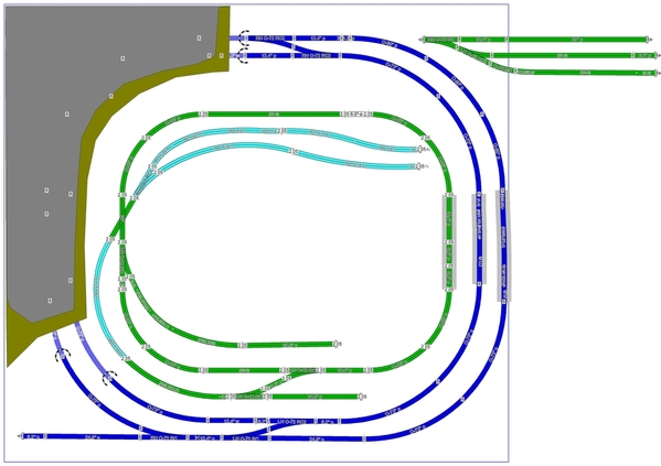
If this were my layout, I'd probably try a double crossover, something like this. It lets one use the Blue route as a passing siding or storage for a 2nd large train. If I wanted to add some buildings, I'd remove the Purple spurs to make room. After looking at the version with numbered switches, I'm not sure how well they'd work, but I'd try them. The one place I can see value in a curved switch is in one or both of the Orange curves coming out of the double crossover.

Attachments
Images (2)
@DoubleDAZ Dave, you got me thinking. I've probably violated some design goals. I used ~3" setback around the edges, not sure what you guys were using. It looks like it will shorten the width of the orange line about 6".
The curves out of the curved switch are all 072 and I moved the 100 and 101 switches a little.

Attachments
Images (1)
080 curves out of the 054 curved switch work even better. This gives 5.5" between the blue main and siding, 4.5" between the siding and double switch.

Attachments
Images (1)
Dan, that’s a really nice configuration. I thought about making a “real” passing siding/storage track that allows smaller trains to use the whole layout unimpeded, but was concerned about reducing the inside space for the operations too much. I don’t know exactly what kind of day-to-day operations Dave plans, how much running vs how much switching to move cars around, etc., I’m not even sure he knows at this point. I’ll merge your design in SCARM and Dave can take it from there. He’s got quite a few options, all with different capabilities and costs.
Here is the finished version.


Attachments
Images (2)


Files (1)
Add Reply
Sign In To Reply

