Hi All;
Made a lot of progress today.....
1. Tested each Track Block (4 per loop) with a volt meter by:
A. Set all the TIU Variable Channels to 22V,
B. Powered down each Track Block at the ZW connected to the Track Block,
C. Powered up each Track Block one at a time at the ZW connected to that Track Block,
D. When one Track Block was powered up, power was confirmed with the voltmeter,
E. Track Blocks on either side of the powered Track Block were checked for power. No power
was shown on Track Blocks on either side of the active/powered Track Block.
F. This process was repeated all around the layout. For example; the loops consist of Track Blocks A,
B, C and D. Track Blocks B and D were checked for power when A was powered up, C and A were
where checked when B was powered up, etc.
G. Bottom line, no "voltage leaks" were found in any Track Blocks adjacent to the powered Track
Block. I did notice that when a lighted passeger car (that has two pickup rollers) was used to
check if a Track Block was active, there was "voltage leak" to a unpowered Track Block, but only
when the car straddled an insulation point; where one pickup roller was on a powered Track Block
and the other pickup roller was on an unpowered Track Block.
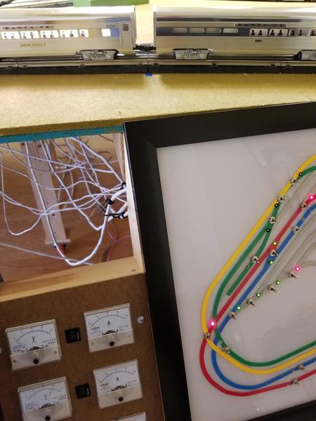
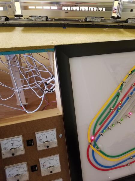
I know this because I was also checking the voltmeters on my Control Panel. I would see voltage
appear on a ZW for an adjacent Track Block that was powered off (see pics below):
This pic shows a lighted passenger car on the powered Track Block which is to the Left of the Blue
tape marker where the insulated pin is. The 2nd voltmeter shows 15 volts. The passenger car to
the Right of the Blue tape is not lit because that Track Block (the top voltmeter) has zero power
to it......

This next pic has the passenger car straddling the insulated pin. As you can see the car now lights
up, and the cars to the Right of the insulated pin are also lighted! Notice the top voltmeter; it now
shows there is power going to the Track Block to the Right of the insulated pin; which had no power
going to it earlier and shouldn't!

2. Received and installed the "magic lights". Yes.....they made quite a difference! I still get "OUT OF RF RANGE", but very briefly. Track Signal is mostly 9 - 10. I need to research those few areas of the track that get "OUT OF RF RANGE". It appears one area is over a group of switches. Another area is through
the Lionel Lift Bridges.
3. I added two engines; one on each loop. I am now able to control each one separately without interference or confusion!
Thank you, Thank You, THANK YOU ALL who took the time to help me out and get my layout more stable than its ever been!!