
My Horse corral seems to like a different voltage than my Banjo signal than my milk car, etc.

How to you provide a different voltage level for each accessory? Do you need a different power supply for each or is there a method to adjust each?

I have no Legacy or Cab-1 yet, but looking into it.

Thanks for any info..


Original Post

Replies sorted oldest to newest

A discussion about AC voltage-dropping is not complete without a cameo appearance of the diode method.  Many OGR threads on this.  Typical implementation would look something like this and cost less than $5.  You'd get multiple, simultaneously use-able outputs.  Not as convenient as a multiple output transformer as it does require component interconnections, wiring, etc.


AC voltage dropping using bridge rectifiers


Attachments

Images (1)
  • AC voltage dropping using bridge rectifiers
Last edited by stan2004

On my PW-style layout I have many accessories and run them off the two channels ('B' and 'C') on my trusty ZW.

But lots of good advice above about different options with smaller transformers. The key, as you know from your horse corral experience, is being able to dial-in the sweet spot on voltage for the particular accessory. The cattle car, barrel loader and milk car, just to name a few, require fine tuning for good operation. Separate, variable voltage is the name of the game.


Last edited by johnstrains

Over the years and two inheritances, I acquired a rebuilt PW ZW, a rebuilt PW KW, and a new ZW with two PH135s, and a couple more PH135s through acquisitions of other items.  Since then, I've gone all PH180s through Legacy PowerMasters for running my trains.  That gives me 10 adjustable AC sources for accessories.  I think I've got enough accessory power for now.  

I don't understand why many are giving DC options when the accessories specifically mentioned are not DC compatible. The hoarse corral and banjo signal uses a vibrator motor and thus needs the cyclical AC to vibrate. The milk car uses a solenoid which can become magnetized and inoperable if used with DC current. Thus the typical wall warts, diode droppers, buck converts and such are not appropriate solutions for the given situation.

bmoran4 posted:

I don't understand why many are giving DC options when the accessories specifically mentioned are not DC compatible. The hoarse corral and banjo signal uses a vibrator motor and thus needs the cyclical AC to vibrate. The milk car uses a solenoid which can become magnetized and inoperable if used with DC current. Thus the typical wall warts, diode droppers, buck converts and such are not appropriate solutions for the given situation.

IMHO the OP was just using those as examples and not limiting the original question of, "What to do when accessories like different voltage ?? "  to only AC accessories. If that were the case, the original title would have probably specified only "AC accessories."

Home layout. My approach, way-back, was that I needed 12 vac, accessory. 18 vac track.  I set up a relatively powerful accessory transformer and paralleled (2) PH135's for track power.

First major ah-shoot was that the Atlas switch motors did do well at 12 vac.  Switched them to 18 vac , worked much better.

Other accessories were O.K. at 12 vac. 

I did install a small DC HO power supply for the turntable.  DC drive on the Diamond scale turntable used a  (dpdtX momentary), double pole, double throw, cross over, (momentary) switch to reverse direct of the TT bridge movement.  There was also a small adjustable variable resistor, that provided some speed control of the TT bridge.  

Fort Pitt Highrailer layout  module pictured above.  Voltages were all over the place.   While the lower voltages were easy, just use the wall wart the equipment came with.  18 volts AC was readily available from different power supplies, as has been mention.  

A Larger problem was that the operating backhoe,  tipping port-a-john, and bear coming out of it's cave, were custom accessories, operated at 110 volts.  While the voltage is available, most train layouts, I really did not want to power operating push buttons with 110 V.  Relays were another problem.  Tough to find relays that operate at 18 volts, a relative common model train voltage.  Solution was to use 24 volt relays to control the 110 volt.  Using an old transformer, pushed all the way UP, full,  the transformer generated  22 volts ac, which operated 24 volt relays.  

There are accessories that will work on a range of voltages, either AC or DC.  May be the new trend. 

Be careful with any and all accessories, once you leave the smoke out, it's a tough fix.   IMO, Mike CT.  

Last edited by Mike CT
Richie C. posted:
bmoran4 posted:

I don't understand why many are giving DC options when the accessories specifically mentioned are not DC compatible. The hoarse corral and banjo signal uses a vibrator motor and thus needs the cyclical AC to vibrate. The milk car uses a solenoid which can become magnetized and inoperable if used with DC current. Thus the typical wall warts, diode droppers, buck converts and such are not appropriate solutions for the given situation.

IMHO the OP was just using those as examples and not limiting the original question of, "What to do when accessories like different voltage ?? "  to only AC accessories. If that were the case, the original title would have probably specified only "AC accessories."

O gauge trains are traditionally AC, therefore no need to specifically call out AC. DC power is the exception to the rule. Offering up DC solutions without the caveat that they will not work with the specifically mentioned accessories (examples or not), is giving incomplete and misleading information. These DC solutions are great for lighting and accessories that can run on DC, but the AC solutions are essentially universal, the DC ones, not so much.

bmoran4 posted:
Richie C. posted:
bmoran4 posted:

I don't understand why many are giving DC options when the accessories specifically mentioned are not DC compatible. The hoarse corral and banjo signal uses a vibrator motor and thus needs the cyclical AC to vibrate. The milk car uses a solenoid which can become magnetized and inoperable if used with DC current. Thus the typical wall warts, diode droppers, buck converts and such are not appropriate solutions for the given situation.

IMHO the OP was just using those as examples and not limiting the original question of, "What to do when accessories like different voltage ?? "  to only AC accessories. If that were the case, the original title would have probably specified only "AC accessories."

O gauge trains are traditionally AC, therefore no need to specifically call out AC. DC power is the exception to the rule. Offering up DC solutions without the caveat that they will not work with the specifically mentioned accessories (examples or not), is giving incomplete and misleading information. These DC solutions are great for lighting and accessories that can run on DC, but the AC solutions are essentially universal, the DC ones, not so much.

Just to be clear, the OP was not asking about AC train operation - he was inquiring, generally, about how to solve the problem of multiple accessories on a layout having differing and varying voltage requirements without limiting his inquiry into either AC or DC operation.

The fact that some people chose to mistakenly interpret and restrict the inquiry to just AC accessories is belied by the number of people who posted potential solutions for DC accessories and who were unfairly criticized.

Many O gauge accessories run on just DC power or can be operated on either AC or DC power and those replies which talked about DC power were neither incomplete nor misleading.

Furthermore, many people read these threads in order to gain general knowledge and information about all kinds of subjects relating to O gauge operation and not just information narrowly tailored to an OP's specific issue and the information contained in those responses may be invaluable to them and, again, is neither incomplete nor misleading.  

Bob "O" posted:

...Your picture shows KBU 806 diodes and the eBay link is for KBU 1010 - what is the difference?

Input is 14 volts AC and the output is also AC? And the voltage is reduced incrementally by the number of diodes used? Have I got this straight?

Good catch!  Bridge rectifiers have a Current (Amps) and Voltage rating.  The KBU806 is an 8 Amp, 600V component.  The KBU1010 is a 10 Amp, 1000V component.  An 8 or 10 Amp capable part ought to be more than sufficient for a handful of accessories.  And since Accessory AC voltages are between, say, 10-20V AC, a 600V or 1000V capable bridge is also more than sufficient.  It almost comes down to what's easy to find - I get the impression that on eBay there are frequently situations where a more capable (more Amps, more Volts) component is less expensive because an Asian manufacturer had a few million extra parts from a production overrun or whatever!

As per the diode dropping method, I'm sure there have been better write-ups in previous OGR threads but to elaborate on the ongoing parallel discussion between DC and AC accessories.  The diode method can apply to DC or AC operation.  The physics/math of a diode can get quite tedious but here's my take:

dc and ac drop using diodes

The most common diode (aka Silicon diode) type will drop a DC voltage by about 0.7V going in one direction.  Add more diodes and you can create a multiple-output (multi-tap) string of voltages that can be used at the same time.  That is, one DC accessory can be tapping the -1.4V drop while another accessory is tapping the -2.1V drop.  Or two accessories might be tapping the -2.8V drop.  The drop is relative to the starting or incoming voltage.  So you could start with 12V DC, or 18V DC or whatever and the taps will scale accordingly.

For AC dropping, you simply use a pair of back-to-back diodes.  One diode of the pair drops ~0.7V when the AC voltage is one polarity, the other diode of the pair drops ~0.7V when the AC voltage is the other polarity.  Again, the drop is relative to the starting AC voltage which does not have to be 14V AC.

The use of a bridge-rectifier is a matter of convenience and assembly ease.  A bridge is simply a package of 4 individual diodes that with a simple connection between its + and - terminals can be configured to be 2 pairs of back-to-back diodes suitable for AC voltage dropping.

4 diodes vs bridge

In above photo, 4 "loose" individual diodes are shown.  Obviously there are 8 terminals to deal with.  The equivalent bridge has 4 terminals, and is packaged with a mounting hole that can be useful for tidy assembly as illustrated on the right.

bridge rectifier as two pairs of diodes

As always, there are i's to dot and t's to cross (aka fine-print) which have been discussed in previous threads but it really works and can be an inexpensive and compact alternative especially if the alternative is to buy more AC output transformers. It seems a lot of guys have unused AC-output transformers lying around so that obviously stacks the deck!

Attachments

Images (3)
  • dc and ac drop using diodes
  • 4 diodes vs bridge
  • bridge rectifier as two pairs of diodes

Stan - I think I get that the bridge rectifier is simply 4 diodes put together for ease of assembly and that each additional diode drops voltage by a set amount.

However, your original picture seems to show 4 bridges of equal value (#806) all configured the same way and no additional diodes added per drop (unless they're hidden), yet you show each drop having a different value ranging from 14v to 9.1v - how is that possible ?


diode drops cascade or daisy-chain

Richie, I think I understand your question.  So what is happening is the leftmost bridge (2 pairs of diodes) performs its dropping function....then feeds the 2nd bridge.  The 2nd bridge takes the reduced voltage from the 1st bridge and drops it some more.  The "output" of the 2nd bridge then feeds the 3rd bridge and so on.  So the voltage drops cascade, daisy-chain, add-up, accumulate, or however you want to think of it.  Not sure I'm being clear but what you see is what you get!  There are no additional hidden diodes or bridges in the photo.

Attachments

Images (1)
  • diode drops cascade or daisy-chain

Thanks, Stan - now I get it - each drop is lowered by 0.7v in a sort of daisy chain arrangement.

I originally thought each bridge was being fed the same 14v, but I can see now that each bridge is only being fed the reduced voltage from the previous drop from left to right.

1. I assume you could mix and match bridges to get different outputs rather than the same drop each time ?

2. Does the blue wire on the right after the last bridge lead back to the original 14v power supply ?

Thanks.


Richie C. posted:

...

1. I assume you could mix and match bridges to get different outputs rather than the same drop each time ?

2. Does the blue wire on the right after the last bridge lead back to the original 14v power supply ?

1.  Not sure what you mean by mix-match, but by using 8 Amp or 10 Amp bridges, you will be able to handle any "reasonable" combination of O gauge accessories.  By reasonable, I mean if your AC transformer was able to power your accessories in the first place, then inserting this voltage-dropping will also be handle those same accessories with the additional benefit of being able to fine-tune the operating voltages to the individual accessories.

2. The blue wire on the right does NOT go back to original AC supply.  It either goes nowhere (not needed) if you don't need the voltage level of the maximum voltage drop...or it could feed additional diode-pairs or bridges to create more voltage drop taps.  As shown (4 bridges in daisy-chain) the maximum drop is about 8 drops of 0.7V each...or up to 5.6V of AC drop.  So a 14V AC starting voltage (on the left) would be about 8.4V AC on the right blue wire.  So if you needed something less than 8.4 AC you would add more diode-pairs (or bridge rectifiers).

A different answer which might answer both your questions is to note that we are talking very inexpensive components!  Usually with components of this type, you get a better deal by using an over-rated part and buying them in quantity.  So even if your accessories draw only 1/2 Amp or whatever, it's no problem to use a 10-Amp capable part.  Using similar parts usually makes for easier assembly...and in this particular situation the size advantage can be palpable.  That is, while individual AC transformer might have individual handles/throttles to fine-tune the voltage, you can also simply attach your accessory to different taps of the daisy-chain and pick the best voltage drop.  Agreed you don't get the infinitely variable adjustability of a throttle.  But it's hard to imagine an O-gauge accessory with a sweet-spot voltage of exactly 11.7V AC (or whatever) that doesn't work equally well at 12V or 11.5V.

Your example shows diodes that have a constant 0.7v drop.

What I meant was to be able to mix different bridges with different diode values on the same board so the voltage drop was not the same, constant 0.7v drop per output. So maybe you would do 0.7v for the first drop, then a different bridge with a 0.9v drop, then another bridge with maybe a 1.1v drop, etc.

You're right about the sweet spot, but just wondering if you could mix them up.

I'm in the PW ZW and V crowd to do what you're asking.  Lots of them around. But....

One of the first things to check on the old transformers is the condition of the line cord.  The old rubber, 'vinyl' (?) cord insulation is not very durable with age, depending a lot on the conditions in which it's been stored/used over the last few decades.  If the cord is stiff, cracked, questionable in any way have it replaced by a competent service station.  The last thing you need is a new safety hazard!

Secondly, you may find a better price for an old ZW that has NOT been updated with a new whistle rectifier.   You won't typically need the whistle control for the accessories you're going to control.  The cost of a repaired ZW is often more than those that have not been updated/repaired.  Simply check the four throttles for smooth motion, putting a voltmeter on the output (with a load, preferably) to see that the peak and intermittent voltages are attainable.  

Thirdly, be sure to properly label each output.  This may be one of those "Duh!" things, but I put it off way too long and ended up...after a many-month hiatus with the layout...having to go through a lot of unnecessary effort identifying voltages and the accessories to which they were attached.  A good DiNozzo would've been appropriate for me!

Lastly, re all of the DC discussion.  Again, I'm old-school.  I think the 60-cycle AC buzz of solenoids is part of the 'schtick' of Lionel and O3R layouts.  But that's a personal preference.  It's a keeper for moi.

Just some thoughts....

KD

Richie C. posted:

Your example shows diodes that have a constant 0.7v drop.

What I meant was to be able to mix different bridges with different diode values on the same board so the voltage drop was not the same, constant 0.7v drop per output. So maybe you would do 0.7v for the first drop, then a different bridge with a 0.9v drop, then another bridge with maybe a 1.1v drop, etc.

You're right about the sweet spot, but just wondering if you could mix them up.

The voltage drop is about 0.7V AC per diode-pair.  It varies part-to-part, it varies with temperature, it varies with how many Amps (current) is running through it.  I'm sure someone can even show it depends on the phase of the moon. 

The key is you don't need to precisely set the voltage drop to fine-tune a particular accessory.  Getting it to within, say, 1 Volt should be good enough.  For example, mechanical wear of the rubber nipples on the driver washers in vibra-motors (e.g., banjo signal) can easily translate to an effective voltage variation of, say, 1 Volt.

But you are correct that there are different diodes that can have vastly different effective voltage drops.  Zener diodes can be paired to effect AC voltage drops of 5V, 10V, 20V, or more in one-fell-swoop (one pair of diodes).  Schottky diodes can be paired to drop, say, 1/4 VAC rather than 0.7 VAC.  But I'll leave those to special situations.  I'm talking about the most common type of diodes that are readily available, easy-to-apply, and inexpensive.

To dig a bit deeper, precisely setting an AC voltage to an O-gauge accessory is a fool's errand...in my opinion of course.  In addition to wear-and-tear of the mechanism itself which changes the "sweet spot" voltage with use, there is the issue of the AC voltage shape itself.   For example, the CW transformer allows you to precisely dial-in the Accessory output voltage to 14V, 13V, 12V, whatever.  But it does so by "chopping" the AC voltage.  So now you get into the geeky world of pure-sine vs. chopped-sine AC voltage where the same voltage measurement can have different effects on an accessory depending on whether it's a purely resistive load (like a bulb) or some kind of electro-mechanism like a vibra-motor or a solenoid.  The conversation just degenerates into techno-babble.  Bottom line is if you have a bunch of spare AC transformers lying around gathering dust, by all means put them to work.  But for a few dollars, it might be worth a look into the diode-dropping method.  There are a lot of guys here on OGR that use this method and are willing to help.

Last edited by stan2004

 Pay no attention to the controls behind the curtain.

The diode is often the most convenient way for me. I usually have something suitible like that laying around.  I haven't bought any in years they are so easily salvaged (?...were easy anyhow; with micro electronics and surface mounts it's a pita. I haven't had anything "new-new" apart lately to see what's more common lately.)

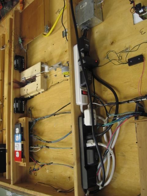
Here are my throttles for a small constant output 12v R.Shack unit that I bet powered a whole lot of home-mounted mobile CB radios across the U.S in the 70s.

 It's throttle is a mix of 2 and 3 postion toggles in 2 old project boxes. Each sw. just adds in a barrel type diode or two in series, with a max of 4 diodes on the far left 3 pos switch (coarsest) Each diode is mounted right on the switch terminals. 

Not "free" free, but "what's-on-hand" kind of free.

  The diodes are not even the same type, size, or brand. They range 4-8 amps (4.5a supply). Im only interested in the voltage drop they have.   I had to test and shuffle them so the left switches are coarser drops; they have a larger volt drop than the switches to the right do.

(I get away with the .5a overage by knowing all my motor draws and appoximating adding the car light amps to have 3.3a constant or lower; peaks at about 4a draw maybe a tad over. It is also pretty much always the last diode to be added in, and going that slow, derailing and shorting to 4.5a trip of the breaker is kinds unlikely as a scenario.  (big deal, I lose one speed check IF it fries... till replaced, I'll still run anyhow)

  Most of the heavy diodes ate more voltage, but not always. There are two 6a that are very efficient, only one 4a is cleaner. Cooler too so I kinda wonder who's it is and the family type. Unfortunately it also stands the best chance at failure being 4a.

 It is more intuitive to use than you might expect too. Partially because of  very predictable drops, partially because of center off on either of two switches on the ends, partially from simple up/fast down/slow operation, and the industrial nature of the toggles allows me to slap a bank up or down 1-5 at a time if I wanted.

The early pre-war transformers operated in a similar stepped way and an additional range selection by tap choice (like the low volt 1033 option of 0-11v vs 5-15v throttle by using a different terminal set.

Hard to see the black box's 5 toggles. They already have a rubber toggle cover for weatherproofing and additional isolation. The "curtain" normally covers it all and moving the toggle with the cloth stretch is easy. No need to look behind the curtain, no vague feel; just don't poke Santa in the face 🎅 ... And the other tip is "Express" means express; as in high/low coarse is best done there.IMG_20190311_173257~2

Attachments

Images (1)
  • IMG_20190311_173257~2

Add Reply

Post

OGR Publishing, Inc., 1310 Eastside Centre Ct, Suite 6, Mountain Home, AR 72653
800-980-OGRR (6477)
www.ogaugerr.com

×
×
×
×
Link copied to your clipboard.
×
×