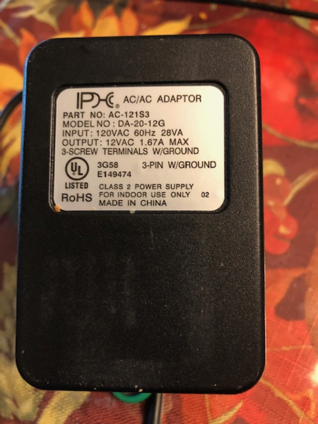
It has three terminal screws for a possible ground. I don't know if the amperage is correct.
Any help would be appreciated.


|
|
It has three terminal screws for a possible ground. I don't know if the amperage is correct.
Any help would be appreciated.
Replies sorted oldest to newest
Command Base? Yes. the ground screw has to be coupled to the coaxial sleeve connection/wire for TMCC signal propagation.
The wall wart is only 12 volts. The usual current maximum voltage for the Powermaster is 18 volts. This may not be a problem if the speed at 12 volts is as fast as you want to run your trains. 4.17 amps is on the low end of the scale (think 35 watts or possibly 50 watts). Whether this amperage is OK depends on what you're planning to run. A single modern can-motor locomotive would probably work as long as it's not pulling passenger cars with incandescent light bulbs.
Manitou,
I think you are confused. As ADCX Rob states, the wall wart is for the COMMAND Base, not the PowerMaster. It powers the electronics in the Command Base, and not the track. On the other hand, a PowerMaster is connected between an AC transformer (such as a LW, KW, ZW, etc.) and the track. It controls voltage and bell/whistle to the track. The power for the PowerMaster's electronics is the AC transformer. Unless you have a big one, you do not use a wall wart in this application.
Chris
LVHR
Thanks for your replies. I am new to O gauge trains, and am trying to get this one set up for my grandson.
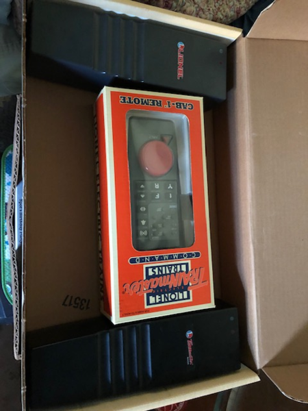
I have this set;
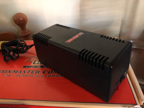
And I have this 135w transfornmer/power supply. I am just trying to find out if I need the wall wart to be able to run.
My (limited) understanding was that I could run conventional (old style) locomotives with what I have, but would need to hook up the Command Base to run Legacy trains.
I might be way off base here, please correct me if I am.
Thanks


As PGentieu stated, the transformer you picked will not have enough power except for maybe one engine. I quickly checked Amazon and they have a few step down transformers from 110 to 15-18 VAC but all produce too little wattage. The one I found that had good output power was over $100.
Also, the PowerMaster requires a special plug and was made to work with a PowerHouse 135 or 180 to run conventional engines with the handheld. You can get this plug, but just more hassle.
My recommendation is to look for PH135. You can find this at a low price now and then.
ADDED: You posted while I was typing. You have everything you need to run TMCC and conventional. Are there instructions in the box.
This might help.

Thanks CAPPilot that's just what I was looking for!!
It appears that the only thing I am still missing is the 120v house current to the Command Base (AKA wall wart)
That is why I was asking if the one that I pictured in my original post would be able to be used It appears to have a ground terminal. I would just need to know where to hook up the ground. I am assuming that I would couple it or jump it to the negative wire.
Thanks again
Robert
@Manitou posted:I am assuming that I would couple it or jump it to the negative wire.
To the sleeve. it's an AC power supply, and you only need 100ma minimum. I have recommended this in the past:

Rob,
Thanks. I was still thinking PowerMaster from the OP. The Command Base power supply is what is missing in Manitou's pictures.
The part number for the adapter is 6102911010 (Part number corrected. Thanks CAPPilot). . Lionel has not had it in stock for awhile.
You can check with S & W Parts Supply to see if they have any.
Someone was able to get one from them in the past.
This is Dale Manquen's schematic for the wall wart supply to the base...

Here's a good video on the TMCC / Legacy options and what you need for conventional control with TMCC is covered.
He covers TMCC very well before moving on to Legacy.
calsz06,
Just looked at my old notes, and the number you gave in your post is for the TMCC command base. The TMCC1 12VAC output wall-pack for this command base is 6102911010.
FYI, the TMCC2 8VAC output wall-pack for the Legacy command base is 6204202001.
Also
You should know that there are two versions of the Command Base. The first one, released before the year 2000, accepts signals around 26 MHz and transmits them to the track at around 450 kHz, and is black. The second Command Base, I think its called Command Base 1L, accepts signals in the 2400 MHz band and transmits to the track at the same 450 kHz, and is blue.
The black one needs a gray CAB-1 remote which has a long antenna (the handheld, not the base). The blue base needs a blue CAB-1L remote and the antenna is built in. They do not mix. For either one, you can buy more remotes.
There may be differences in the voltage levels of the 9-pin serial port connector, should not matter to you.
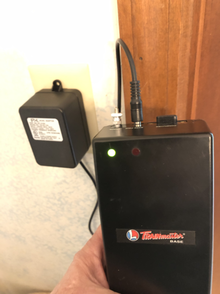
I happen to have both, never got around to selling the first black one. So I went digging in storage boxes, found the base, and of course could not find the transformer/wall wart. I finally found it powering up a Lionel switch controller on my floor layout. I hooked up the old Command Base and the green LED came on, put batteries in a gray CAB-1, spun the dial, and the red LED flickered, indicating it is receiving commands. So I took a picture of the label ...

I have searched on the internet, and each transformer that I have found that claims to be a replacement does not have the third grounding plug, so I will not post any of these. Giving up for now.
Third edit: In CAPPilot's diagram, it would help with the wall wart for the Command Base had the third prong.
Even if they have the grounding pin on the 120V side, it's unlikely that it's bonded to the secondary like the TMCC command base transformer. I have some alarm system AC transformers that have the ground pin, but it goes nowhere but inside. I surmise, though I can't prove it, it's some sort of faraday shield between the primary and secondary windings.
@gunrunnerjohn posted:Even if they have the grounding pin on the 120V side, it's unlikely that it's bonded to the secondary like the TMCC command base transformer...
Tip or sleeve? I haven't had a chance to pull one out yet.
The ground pin on the TMCC wall wart goes to the outside of the barrel.
@illinoiscentral posted:Third edit: In CAPPilot's diagram, it would help with the wall wart for the Command Base had the third prong.
Done
Thanks for all of your help.
One last question, what is the size of the plug that fits into the Trainmaster B-1 base?
I measured with my dial calipers and got a .230 diameter opening. That is roughly 5.8mm. Should I assume a 6mm plug?
Thanks again
Coaxial power plug 5.5 x 2.5 mm or 5.5 x 2.1 mm
Measure the inside pin to get the 2.5 or 2.1
My Legacy base is 2.5
Thank You Sir!
All the TMCC and Legacy bases us 5.5/2.5 barrel connectors.
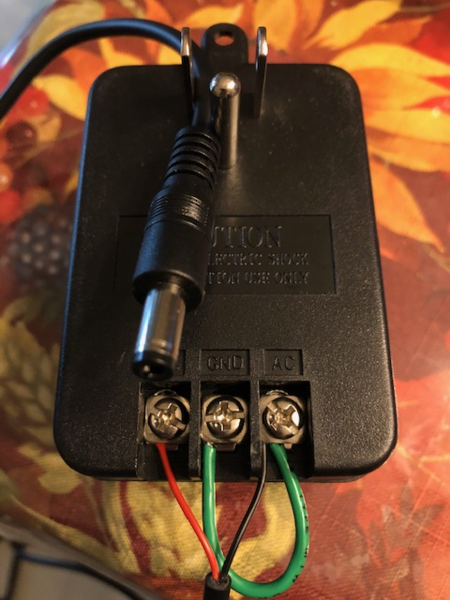
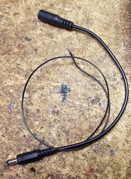
I got my wall wart in the mail and also the 5.5 x 2.5 barrel connector.
I wired it up according to how I think it should go but before I plug it in I wanted to ask if it looked OK to the more informed people here.
The black wire has continuity to the barrel (outside) of the plug.

If the output is 12 VAC, you're good to go with the old TMCC BASE1.
Looks OK to me.
Thanks for all of your help.
Maybe this thread will be usefu to someone in the future who is looking for a replacement power supply for the ones that are no longer made.
Edited to add;
I plugged it into the wall with no ill effects and the plugged it into the Trainmaster base, and it lit the green light with no smoking or other issues due to improper current.

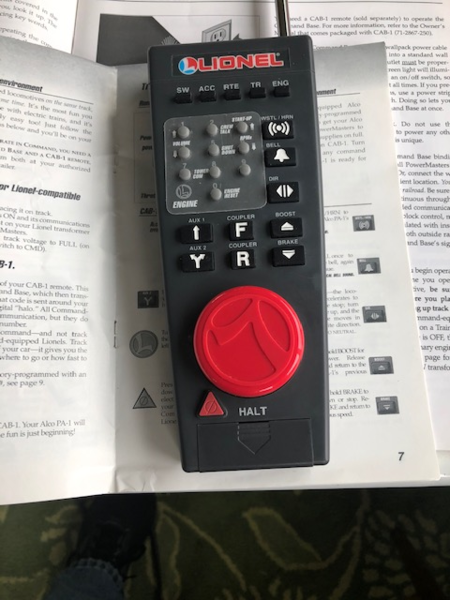
I got the track and the Locomotive from my daughter (this train is for my 5 yr. old grandson) and hooked everything up according to the directions this morning, and although the train runs, I cannot control it at all with the hand held CAB-1 unit.
The locomotive is a 2000 ATSF Railway ALCO PA-1 Diesel locomotive. Says it is Command Equipped with signal sounds. Number 6-18952
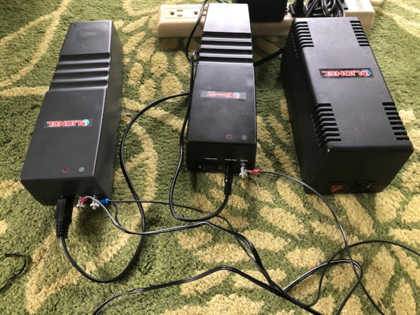
The "U" post on the TMCC TrainMaster Base (center in above picture) is jumped to the "U" post on the PM-1 PowerMaster (left in the above photo) which is then connected to the outside rail. The "A" post is connected to the center rail. I have connected the large transformer (right side of above picture) with it's special plug to the PowerMaster (left) and my home-made and hopefully correctly grounded wall wart to the TMCC.
The CAB-1 has fresh batteries
Do you suppose that my ground jumped wall wart is not grounded? I jumped from the ground output to the barrel of the plug.
As mentioned above, the train will run, but it will not accept any direction from the handheld CAB-1. When I depress any buttons or keys on the CAB-1, there is flashing of the lights on top of the TMCC and PM-1, so it seems like they are getting signal from the CAB-1.
Any help would be appreciated.
Thanks
Robert


Lose the PowerMaster, you don't need it with command controlled equipment. Just connect the U terminal on the command base to the outside rail of the track, fire up your transformer with the engine on the tracks, you're good to go.
Note that you may have to set the TMCC ID of the locomotive, check the ALCo PA A-A Diesel Loco Set - 8/03 User's Manual for instructions of how to set the TMCC ID.
I am confused. If I remove the Powermaster (left in the above picture) I will not have power to the track. My transformer runs through the PM-1 to the track. If I remove it, I will have no power to the track.
Hook the power directly to the track, you don't need the PowerMaster for command operation. If you leave the PowerMaster, did you switch it to command mode?
I have no way to run power directly from my 135W powerhouse directly to the track. There is a special connector on the end of thepowerhouse wire that has a pointed shaped area that only fits into the PowerMaster (PM-1).
The train will run around the track. There is no stopping it or slowing it down. The horn sounds arbitrarily. Sometimes the horn sounds when I depress any button on the CAB-1. The boost button seems to be the only other button that works and will speed the train up until it derails
Here's the product page for for the PowerMaster, the manuals and tips are downloadable there: Lionel 6-24130 TMCC PowerMaster
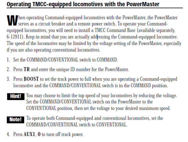
Again, did you set the switches correctly?
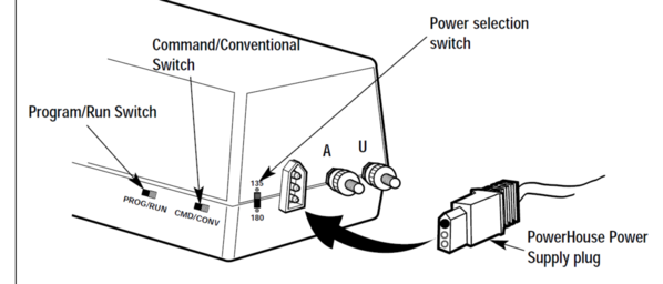
First off, the CMD/CONV switch should be in the CMD position. The 135/180 switch should be in the 135 position for that brick. Finally, the PROG/RUN switch should be in RUN.
You need to use the TR key to select the train # programmed into the PM. If you don't know what it is, set the PGM/RUN switch to PGM, press TR, #, and SET. The # is the train number you want it to respond two, from 1 to 9, a single digit.
Here's the command operation page for the PowerMaster.


gunrunnerjohn,
Sorry that I didn't address the switches in my last post. The CMD/CONV switch is set to CMD. The PROG/RUN switch is set to RUN. There is no 135/180 switch on this unit, it must be an older model.
I will set the PGM/RUN switch to PGM and program the train as train 1 on track 1, and try again.
Thanks for your patience with this newbee.
Robert
I do believe there was an early model without the power switch before the 180W brick came out.
I just cannot slow down the train, or halt it in any way. I can only put the train on the track with the power turned completely off. Once I turn the power switch on the train springs to life. If I rotate the red knob on the CAB-1 clockwise, the train will speed up to the point that it de-rails going around a bend. If I rotate it counter clockwise, it does nothing.
@Manitou posted:I just cannot slow down the train, or halt it in any way. I can only put the train on the track with the power turned completely off. Once I turn the power switch on the train springs to life. If I rotate the red knob on the CAB-1 clockwise, the train will speed up to the point that it de-rails going around a bend. If I rotate it counter clockwise, it does nothing.
The Command Base must be powered up before the track so the TMCC equipment knows whether to come up in conventional or command. Let's eliminate the PM-1 as your roadblock:
Hotwire that PH-1 directly to the track w/o the PM-1 using wire stripped & folded back on itself to plug in to the two occupied sockets on the PH-1 cord - polarity doesn't matter for this test but the PM-1 passes the center socket to "A" and the outside one to "U" if you want to keep it straight for logic continuity. Connect Command Base "U" to an outside rail.
Power up the Command Base. Check with your remote that the base is receiving signals from the remote - light flashes on base.
Put the train on the track and, keeping your finger on the switch, power up the PH-1. If it takes off in conventional, it is not receiving a TMCC signal from the base... shut down PH-1 immediately to avoid crashing, and go back to your power supply and maybe switch the ground coupling to the other AC output and test again.
I haven't tried to hotwire the PH-1 to the track yet, but I did switch the ground to the center pin of the wall wart earlier tonight with no change whatsoever
Rob,
I did as you said, and jumped the PH-1 directly to the track. I powered up the Base-1 with the wall wart first, and then (with the Base-1 set to conventional) I powered up the PH-1 and the train took off. Could something be wrong with the CAB-1?
Robert
Your command base has a problem.
So what would my next step be? Repair or replace?
That power supply appears to have only two prongs for the wall plug and it is missing the third ground pin.
Are you sure it would work? one of the reviews states that it doesn't and reccomends the pin 5 serial connector to ground remedy.
As GRJ stated, "repair or replace?". I would vote for replace. But one last test:
The TMCC Command Base broadcasts its RF signal A) into the outside rails of the track via the track wire connection, and B) into the house wiring ground (green wire). The TMCC receiver in the locomotive senses the RF voltage from the track and the signal emanating from the house wiring.
At this point, the replacement wall wart is powering the Command Base which is responding to the CAB-1 remote (red LED flickers). The ALCO PA-1 is not responding the the TMCC signal. Potential causes: the Command Base may not be transmitting the RF signal; the antenna (house ground connection) is not connected; or the ALCO's TMCC receiver (or antenna inside the engine) may be at fault.
Two TMCC receivers are on hand - the 6-24130 PowerMaster, and the 6-18952 ALCO PA-1 Diesel. We know the ALCO is not responding correctly.
The first test I would run would be to determine if the TMCC Base is transmitting the RF signal to the Powermaster. Does the Powermaster have a flickering green LED that indicates a weak RF signal? If the LED is solid green, set up the PowerMaster to run in conventional mode and determine if it can be commanded using the CAB-1 to control track voltage. If you can verify that the TMCC PowerMaster is receiving the RF signal and responding to TMCC commands, then the ALCO's TMCC receiver/antenna is probably failed.
If the TMCC PowerMaster has a flickering green light and/or is not responding to TMCC commands from the CAB-1, then look at the RF signal broadcast from the Command Base. The signal via the wall wart power connection may not be getting to the house wiring. This can be overcome by connecting a wire to your black/green wires on the wart and running that wire alongside the track and PowerMaster. This provides an "known good" alternative antenna for the TMCC signal (*). If both the PowerMaster (in conventional mode) and ALCO still don't respond, then the Command Base's RF output has likely failed. Replace the Command Base.
If the ALCO's TMCC reception is bad, then I would open up the ALCO and look for a bad antenna connection. The antenna is likely a copper strip hot glued to the underside of the loco's shell with a wire to the electronics. If these have come apart, the loco can't receive TMCC commands.
(*) Another source for the Command Base's RF output is pin 5 of the DB-9 serial connection.
That supply will not work without supplying a separate earth ground from the command base. In any case, I'm not sure why you'd need a power supply if the base is powering up and seeing the remote! Yet another mis-informed vendor selling something that will NOT work for the advertised purpose! ![]()
A Powermaster receives its commands directly from the Cab1. It does not get its signal from the command base. The powermaster and Cab1 were released before the command base.
Some of the variables need to be eliminated to get a better sense of what’s happening although from what we are gathering it is looking like the TMCC base.
Both the Base-1 and the Powermaster have strong green lights that do not flicker. When any buttons are pressed or the red throttle knob on the CAB-1 are manipulated the red light will flicker on both the Base-1 and the Powermaster giving the indication that they are receiving signal.
I will check to make sure that the Alco's antenna is intact, but (I realize my knowledge is very limited) I am really wondering about the grounding connection in my home made wall wart. It is the only "non-standard"/"non Lionel" component
You need to either take pin-5 of the serial port or the outside of the power barrel jack to earth ground (3rd prong) for proper operation.
To do the pin 5 modification, would I need to open up the Base-1 and jump to the inside of the serial connector, or just insert the wire into the pin 5 plug hole?
Just connect to pin-5 of the connector, no need to open the base.
I had the same requirement with the TMCC Booster Project, I made a jumper cable for the power with a tap for the earth ground from the outside of the barrel for tapping earth ground to the buffer.

I will give it a try, thanks
May notget to until Tuesday
Manitou, try the alternate antenna wire before disassembling the loco. If you have a DB-9 male connector handy, pin 5 is the recommended antenna output for improving the TMCC signal. (Pin 5 and the sleeve connector of the Command Base should be electrically connected.)
Marty, I was describing the current PowerMaster operation which gets the TMCC signal from whatever base is used (Legacy, 1L, or original TMCC Command Base). Do you know what year Lionel switched the design to TMCC RF?
Manitou, if you have an early PowerMaster that gets signal directly from the 27.255 MHz CAB-1 signal, then disconnect the TMCC command base and run the ALCO in conventional mode.
The Legacy Powermaster is the first to use the “track signal”.
The Alco is a 2000 model locomotive.
I am assuming that the other components are similar vintage
I finally got around to setting everthing back up for my O gauge. I took a single strand wire and inserted it into the serial connection terminal pin #5 and ran that directly to the house ground pin where the home made wall wart plugged into the power strip. I powered up the power strip which powered the Base-1 and PM-1(but left the 135w Power house transformer turned off ). I placed the Alco-1 locomotive on the tracks and let it communicate. After about 30 seconds I turned on the Powehouse and the train runs as it is supposed to. I can control the speed and the bell and horn sound when their respective buttons are depressed.
Thank you for all of your help.
Access to this requires an OGR Forum Supporting Membership