
Finally, Side Rod and Ken, I agree with your suggestion that maybe the simplest solution (or test) is to replace the track and turnout.


I would also caution, if you never "bulletproofed" the internal folded tab connections of the switch, and then replacing with a new switch straight from Lionel also uncorrected and not soldered, that's just not smart IMO.

022B3516-042A-460E-820C-8AB3FD65125A072Fastrack_20Switch_20Solder_20Updatefolfed tab program failure

Attachments

Images (4)
  • 022B3516-042A-460E-820C-8AB3FD65125A
  • 072
  • Fastrack_20Switch_20Solder_20Update
  • folfed tab program failure
Last edited by Vernon Barry

Thank you, David.  This was not suggested before, and I do appreciate the suggestion.  Just to clarify, did you mean the wire for track power, the ground wire, or both wires?  I'm assuming the answer is both wires.  The problem section of track is made up of 4-5 pieces of track  and a turnout, so presumably I would need to try this for each of them.

I just realized that connecting wires between good track and each of the problem tracks will require pulling up the track anyway, since the connection points for FasTrack pieces  are only accessible from below the molded plastic roadbed.  It'd be a lot easier if I had just used Gargraves track when I built the layout 20 years ago!

As John noted, temporarily solder to the exposed rail, running the wire along the inside of the track far enough into the sections that are ok so you can run the trains "normally" along the problem section. I'd start with the first section you identified as causing the undesired behavior and see if anything changes, 

A crude image is attached to illustrate the approach with a wire here soldered to the center rail and then running along your track far enough to run the trains over the wire in the testing sections of track.

wire_example

Attachments

Images (1)
  • wire_example
@David_NJ posted:

As John noted, temporarily solder to the exposed rail, running the wire along the inside of the track far enough into the sections that are ok so you can run the trains "normally" along the problem section. I'd start with the first section you identified as causing the undesired behavior and see if anything changes

I was actually suggesting you just jumper the joints with a short piece of wire.

Thanks, John and David -- I'll try what you're suggesting as soon as I can.  I really appreciate your giving me a way to test the connections without just ripping out the track and landscaping.  Have to confess I never thought of soldering the jumpers/wires -- I was still stuck way back on alligator clips as jumpers and how to attach them to the rails without the derailing the engine.

Am I correct in presuming that there should be jumpers/wires for both the middle and outer rails?

Can either of you tell me whether the problem could be 1) signal loss or 2) power interruption?  Specifically, I'm wondering if it might be helpful to try the jumpers/wires only for 1 of the the outside rails first, to see if the TMCC signal is OK or not.  Then add the jumpers/wires for the middle rail.

Thank you both again for your guidance.

I would suspect middle rail first.

Why? Easy, because the outer rails are redundant. Each section of fastrack normally has the shorting bar/plate that connects the outer 2 rails.

Now granted- that is the same folded tab construction that is known to loosen over time and potentially be subject to intermittent connection or higher resistance, but again, each typical curved or straight section of fastrack has this, so it makes a redundant and parallel connection down the outer rails of the track like a ladder if viewed from above. If one single outer joint was bad, in theory this bridges that failure.

This is the same reason I posted the switch information. That is because the center rail and it's connections are also folded tab through the switch- and thus a known possible failure point. So again, this area specifically is likely depending on the switch to carry power through it, center rail, and then center rail is also not redundant/parallel connections in track pieces making it prone to high resistance or intermittent connection through them.

Inside the switch, this stamped metal plate T or Y shaped and folded tab connections (not soldered from the factory) easily explains a loss of power or higher resistance intermittent connections as load and the weight of a train crosses.


Oh look, there is a switch there, right in the middle of this "dead zone" , heavily depending on it for carrying and connecting power- specifically center rail.

Attachments

Images (2)
  • mceclip0
  • mceclip1
Last edited by Vernon Barry

Vernon - thank you for the excellent explanation.  I was wondering how to tell if the turnout was the problem, and your tutorial does it very nicely.  Your detective work in narrowing down the problem to the turnout is impressive.

John, thanks to you as well for the confirmation and added perspective.  I wish I'd known this 20 years ago when I first built the layout!

John - Now I feel much better!  Of course, I still have the track dead zone...

Vernon -- are you saying the problem could be either or both 1) weakened connections between pieces of track and/or 2) loose tabs on the turnout?

I agree that soldering the tabs on the switch like you did, John, is a must, once I pull up the track in the problem area.  But before I do that, do you both (John and Vernon) think I should test all the track pieces for weakened connections by connecting them with jumper wires to the nearest track with power? 

Thanks again to both of you.

John - Now I feel much better!  Of course, I still have the track dead zone...

Vernon -- are you saying the problem could be either or both 1) weakened connections between pieces of track and/or 2) loose tabs on the turnout?

BOTH- you only get a true dead spot/section if BOTH sides are not connected right??? If it was ONLY the switch, then in theory, that leg gets power from the nearest power drop further down the line.

I agree that soldering the tabs on the switch like you did, John, is a must, once I pull up the track in the problem area.  But before I do that, do you both (John and Vernon) think I should test all the track pieces for weakened connections by connecting them with jumper wires to the nearest track with power?

Thanks again to both of you.

OK, let's gather more info and make an informed decision. Without knowing where your power drops are relative, at best we can just do "best practice".

Where in the above diagram (or maybe the larger original one if they are further away), are the nearest track power drop points before/after the switch?

Point being, you would then be jumpering from that back towards the switch.

It is hard to tell from the picture where discrete pieces of track are. It appears the loss starts on either side of the switch. My suggestion is to temporarily solder the first piece of track where it starts to drop out, to the piece before it that seems to be fine. In the snippet picture above, it would look something like this to see if it changes where the drop starts.


Take that first step and see if the shutdown area shrinks.

Attachments

Images (1)
  • mceclip0

Vernon and David,

Thank you both very much – your comments have led me to realize that I need to do more testing to pinpoint the exact location where the engines fail.  I’ll post again with the test results and a better schematic when I have more time tomorrow.

I really appreciate your continuing interest and insights, and look forward to what you think after I complete the additional testing.

Thanks to DavidNJ's suggestion, I repeated my prior testing and extended it in order to find the exact point at which the engine dies in the problem section of track.

When Engine Is Moving Slowly

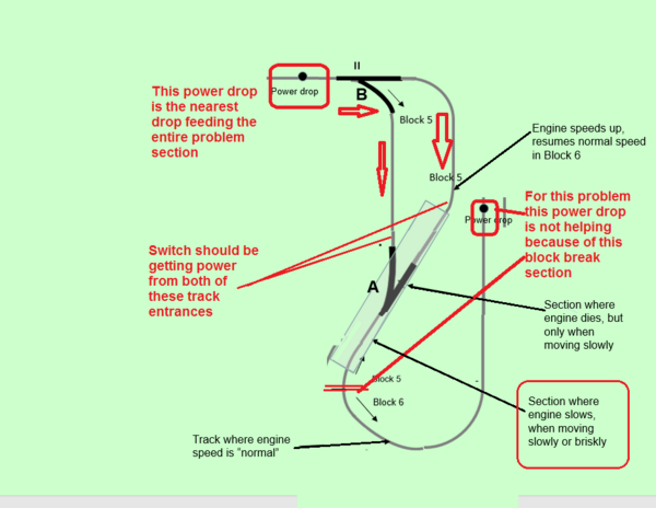
To replicate the test I did before the initial post, I ran the engine through the problem section of track (Block 5 in the diagram below) moving slowly (what I remember of freight train speed), both clockwise and counterclockwise on the layout.

Moving clockwise -- As soon as the engine enters Block 5, and before reaching the switch marked A below, the engine slows down somewhat but does not stop yet.  Track voltage right behind the engine was 13.6v.  In Block 6 just before Block 5, the voltage was 15.8v.  When the engine moves over the switch heading straight out of it, however, it comes to a halt and immediately shuts down, with no power, sound, or lights.  

Moving counterclockwise – The engine moves normally all the way through the switch marked B.  When it reaches the curve after switch B, the engine slows down but does not stop.  When the nose of the engine is over the switch, the engine comes to a halt and immediate shuts down, no power, lights or sound.

When Engine Is Moving Briskly

Moving clockwise -- Next I repeated the test procedure with the engine moving “briskly,” but not breakneck speed.  Starting in Block 6 and moving clockwise, as it crosses into Block 5, the engine slows down but doesn’t stop.  Just before entering switch A, it starts to run jerkily, but the engine doesn’t die – it just continues all the way through the switch A at the reduced speed.  After leaving switch A and approaching the curve leading to switch B, it picks up speed and resumes its original speed before entering Block 5 and everywhere else on the layout.

Moving counterclockwise – Here the engine is moving briskly as it crosses straight through switch B.  As it approaches the curve after switch B and before switch A, it slows down somewhat, but it still proceeds through the switch without stopping.  It moves at the slower speed until it reaches Block 6, at which point it resumes its previous brisk speed.

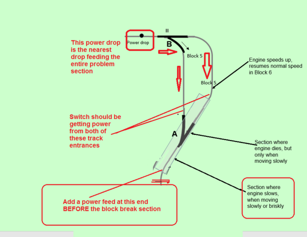
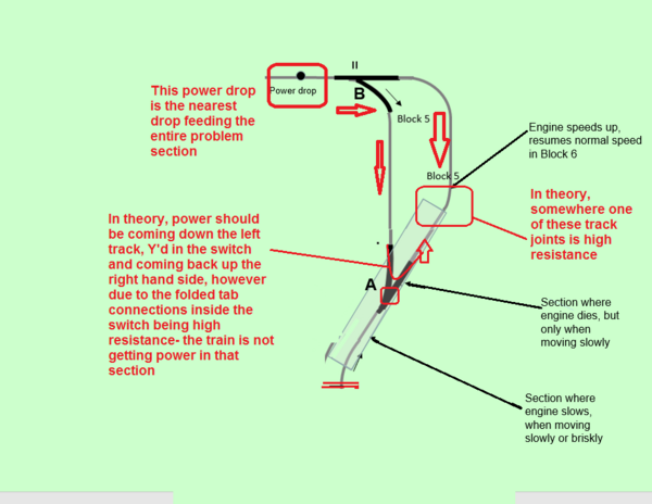
All the above occur when the engine is heading straight out of switch A.  If the engine is taking the left turnout direction from switch A, it does not stop over the switch, at either speed.  It only dies when moving slowly and heading straight out of switch A.  

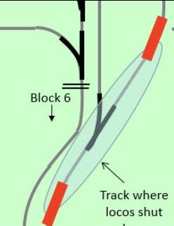
Attached is a layout schematic showing the problem area in Block 5.

Attachments

Images (1)
  • Layout Schematic with Problem Area in Block 5

You can play whack-a-mole and incrementally run jumpers but what I would do is run a wire along the inside of the track between where you show the power drop for block 5 at the top of your picture to the straight section on switch A with a little drop of solder at the two end points. If you have a soldering iron and solder, it should just take 5 mins to do this.

Running faster probably allows the engine enough momentum to get past a power drop before it stops.

I have nowhere near the experience as others and they might have other suggestions.

The answer is slapping us in the face- it's exactly what I said.

#1 You only have power feed entry point far from this section at one end only.

#2 That power has to go through 2 fastrack switches, and all the track joints to get to the section of track in the next block.

#3 As pointed out- the internal folded tab connections in the switch can and will likely go high resistance and/or intermittent contact thus affection power traveling THROUGH the switch legs from one end to the other.

Again, plain as day, we have high resistance connections in the 2 parallel legs of track between these 2 switches.

Further, even if only one side had high resistance, the "problem" area switch should be combining and paralleling and clearly it's NOT meaning we know, beyond any shadow of doubt- you probably should be opening that switch and breaking out the soldering iron.

Both switches likely have some level of high resistance in these folded tabs that only will get worse with time and usage. That said, the entire problem is compounded by lack of power feeds and where you chose to make your block sections.

Attachments

Images (1)
  • mceclip0

Vernon and David - thank you both for your willingness to continue to help me.

Vernon, your post and the comments you put directly on the layout diagram are extremely helpful.  It's now abundantly clear what I need to do next -- pull up the switches and track, solder the tabs on both switches, and add 2 power drops in between the A and B switches in Block 5, one on each to the parallel tracks.  These considerations you pointed out never crossed my mind when I built the layout -- I wish I'd post a layout schematic on the Forum and asked for comments from the community.  Regardless, I'm very grateful to have your diagnosis.

David, I really appreciate your sticking with my problem, as well as your suggestion of the temporary soldering.  What gauge wire would you use for this?  I'd think 18 gauge to fit beneath the pick up roller of the engine passing overhead, but I'm concerned it not being big enough to safely carry the current.  I may try this before taking up the track to see if it points to the same conclusions above.

Thanks again,

Vernon, your post and the comments you put directly on the layout diagram are extremely helpful.  It's now abundantly clear what I need to do next -- pull up the switches and track, solder the tabs on both switches, and add 2 power drops in between the A and B switches in Block 5, one on each to the parallel tracks.

Just add a feed at the dead end of the track. Again, that's 99% of the problem here, only one power drop, at the complete opposite end to the problem area.

Edit- I agree, yes, you should add additional power feeds in the tracks between the 2 switches (the legs), but bare absolute common sense minimum there should be a feed where I indicated before the next track break section for the next block.

Attachments

Images (1)
  • mceclip0
Last edited by Vernon Barry

David, ...............your suggestion of the temporary soldering.  What gauge wire would you use for this?  I'd think 18 gauge to fit beneath the pick up roller of the engine passing overhead, but I'm concerned it not being big enough to safely carry the current.  I may try this before taking up the track to see if it points to the same conclusions above.

I think this is a failed approach and here is why. Edit, sorry, I think failed is too strong of a word. I just was trying to share my concern this would not be the "best" first approach in solving this- short or long term.

This solves primarily jumpering across a suspected bad track joint. The assumption is, you have a GOOD feed on one side and only one joint is really the problem.

The problem is, we already know, you have a lack of track feeds. In fact, you likely before all this still had less power in the problem area always, just maybe not bad enough to stop an engine.

Edit- sorry for the different size arrows. That is not intentional and does not represent a difference based on size of the arrow. I was just trying to show the direction of power flowing from the single drop point at the top of the drawing.

Again, jumpering across a joint is good for one joint- however in a scenario where your entire block section only has a feed at the far end- unless you jumper every single joint, you are just kicking the can down the road.

Attachments

Images (1)
  • mceclip0
Last edited by Vernon Barry

I dont' take any criticism personally, especially when it comes to experience in troubleshoot track issues like this.

My suggestion would be the switch as it seems to be the center point of the problem. If the switch isn't defective or has a bad connection to the other track, the end piece of that block should be fine . My suggestion for the switch was it seemed to be the middle of the problem area and if it was something possibly on either side of the switch which is impacting the flow, it might still remain.

It shouldn't matter much which temporary wire you use for this as long as you can keep it below the height of the rails. You can take it off right after you run the test.

I would suggest just doing something a this point as it would probably take less time than creating another reply and we'd all gain some new info.


Vernon, thanks for the followup.  I'm glad you pointed out the need for a power drop between switch A and the end of the block, so that power is coming into the switch from both sides.  It's what you said originally but somehow it must have failed to register.

John, I'll definitely solder the tabs on the back of switch A.  I presume you're referring to soldering the tabs that are connected to a metal strip.

David and John, you're absolutely correct - it's time for action.  I now have a very clear idea of how to proceed.  Sincere thanks to all of you.  I'll definitely post how things work out.

Again, you have to remove the metal back cover, then possibly move the wires slightly to be able to see all the various folded tab connections.

Review the pictures in this post- and long term, especially any new switches you install, recommend doing this before putting on the layout, then adding scenery and then having to pull it up later to correct the issue.

https://ogrforum.ogaugerr.com/...9#179369391710823089

I would suspect middle rail first.

Why? Easy, because the outer rails are redundant. Each section of fastrack normally has the shorting bar/plate that connects the outer 2 rails.

Now granted- that is the same folded tab construction that is known to loosen over time and potentially be subject to intermittent connection or higher resistance, but again, each typical curved or straight section of fastrack has this, so it makes a redundant and parallel connection down the outer rails of the track like a ladder if viewed from above. If one single outer joint was bad, in theory this bridges that failure.

This is the same reason I posted the switch information. That is because the center rail and it's connections are also folded tab through the switch- and thus a known possible failure point. So again, this area specifically is likely depending on the switch to carry power through it, center rail, and then center rail is also not redundant/parallel connections in track pieces making it prone to high resistance or intermittent connection through them.

Inside the switch, this stamped metal plate T or Y shaped and folded tab connections (not soldered from the factory) easily explains a loss of power or higher resistance intermittent connections as load and the weight of a train crosses.

This picture below shows folded tab connections that have been soldered to ensure strong electrical connectivity and minimal resistance and be robust with usage and time.


Again, cannot stress enough, long term, with usage, oxidation, expansion and contraction, the folded tab connects degrade through usage. If your entire track plan has minimal track feeds- all your switches are further stressed components because they are carrying the current through them.

Add Reply

Post

OGR Publishing, Inc., 1310 Eastside Centre Ct, Suite 6, Mountain Home, AR 72653
800-980-OGRR (6477)
www.ogaugerr.com

×
×
×
×
Link copied to your clipboard.
×
×