
Recently, I purchased Lionel's awesome 12782 Lift Bridge made in 1992 from a fellow-awesome forum member (Thanks much Peter~). I was planning on putting it on a wood base before fully installing it on my layout, but I did want to test it without securing first just to make sure, as per instructions.


The good news was the bridge functioned perfectly!


The bad news is not long after testing it a day or two, the controller suddenly started to smell smokey, primarily near the on/off switch. I'm pretty sure there's a mystery short somewhere, as the lights and bridge won't come on as should normally, though I don't know if it's in the bridge itself or in the controller. The short only occurs when trying to plug the bridge into the controller, and it is apparently trying to get a response. By comparison, the bridge isn't making any smells, which is a slightly good sign.


Anyone have a diagnosis for what the problem exactly could be, and how to rectify it?

Last edited by Mikado 4501
Original Post

Replies sorted oldest to newest

The mini rocker switch in the controller has a history of failure. There are no parts out there for these controllers. I have two bridges and one controller rocker switch failed. Power for all bridge functions(lights etc) passes thru the controller. Sooo you have to open the controller and re wire the controller so power will by pass the switch unless you have a electronics house around that might have that mini rocker switch, then you could replace it. I have been batting zero with that. Now when bypassing the switch bridge power will always be on and if the bridge jams in being raised or lowered un plug the banana pin from the back of the controller to the wall wart to reset the remote. Hope this helps I love those bridges.


liftbr 001

Attachments

Images (1)
  • liftbr  001
Last edited by dk122trains

Thank you for the picture. Now if I may trouble you for a picture of the inside of the controller, specifically of the power switch, which is apparently the problem component. The length and width dimensions of the switch as measured from inside the box would help immensely in trying to locate a possible replacement.


Thanks again for your help.


Larry

Originally Posted by TrainLarry:

Thank you for the picture. Now if I may trouble you for a picture of the inside of the controller, specifically of the power switch, which is apparently the problem component. The length and width dimensions of the switch as measured from inside the box would help immensely in trying to locate a possible replacement.


Thanks again for your help.


Larry

I would, but looking inside already, the board is permanently attached to cover the connections between it and the buttons...

Thomas, looks like you have the solution and a rocker switch should be an easy bypass. l hope you enjoy the bridge as much as I did.  The only reason I sold it is because I am in a major remodel of my layout and am going from a single to two track main line and there would not be room for a second lift bridge.


Peter


IMG_0085

Attachments

Images (1)
  • IMG_0085

Thehousing that contains the power switch is plastic. The case hole could be filed larger for a slightly larger switch...I would also see if the original manufacturers part identification is on the switch..you might be able to locate a replacement..


The previous poster stated they were prone to failure...so , a current bump up is needed...

My box went bad years ago.  Dotty and I spent years trying to find one.  This bridge was made for Lionel by MTH.  Mike did his best to find a wiring diagram overseas with no luck and Mike Reagan could not come up with it at Lionel.  A few months ago Dotty found a box  on another site. 


They all go bad with the rocker doing what yours did.  Do not get happy yet until you put in the new switch.  I wish you the best.  Not many get lucky with this.

Last edited by Marty Fitzhenry

Thanks all for the advice,


Unfortunately, as Marty said, the parts for this accessory are like finding a blue tulip.


Dave, I'm probably going to take your advice being a fellow Jersey hobbyist. Those guys probably also have a better technique of separating the top circuit board from the buttons and switches, as it's permanently mounted by looking inside...

My goal on finding a schematic was to redesign a project box with the switches to get the job done.   Mike W and Mike R gave it a good effort but it was not to be had.   Searching for this box was an effort with no results.  Dotty found a box  on fleabay with all the accessories NIB for $49.00.  That was the find of a lifetime.  Now I am searching to find more as Charlie has some bridges at the store with the same issue.  I know the box I have will also die and I am still in hopes to find the schematic to build a few for guys who need them and an extra for myself. 

Mike Wolf had it made and he gave every effort to get me one.  Lionel has nothing available.  Larry,  anything can be done, you are correct.  Take a look at one of those boards and let us know what you think.  Manny smart people have looked at this to do just that.  Cost wise, who can justify the job to do a few boards. 


My next step if I did not find a box was to get out the continuity meter and try to create something.  The plug that goes into the box has twelve wires.

Last edited by Marty Fitzhenry

Looks like my options are:


A) Get a new controller (which is very unlikely...)


B) Bypass the switch entirely to keep the bridge on unless you unplug it (which sounds the least time consuming).


or


C) Get a new rocker switch


It seems everybody has a different opinion what's best, so I'm really going to have to think about this to fix this thing...

Originally Posted by Fredstrains:

I bypassed the Switch years ago, extended the wires out of the Control Box. and put an EXTERNAL TOGGLE SWITCH on my Control Panel.


Worked for the last 10 years


Fred

The Simplest fix!!! AND it works!!!!!


FREDTRAINS

Maybe I'll just do that instead Fred, when I next drop by RadioShack...

I have changed similar rocker switches in laminators, once ordering a factory replacement at $40.00, (not applicable in this situation), and replaced one with a slightly larger switch, making the opening slightly larger, as was suggested above, for $4.00 0r $5.00. The cause of the failure would be interesting to know, ie. bad switch, undersized wire. In this instance, it appears to be the switch. Either remedy, enlarging the opening, or adding an external switch is better then bypassing the faulty one, and risking damage to the bridge. Obviously, the limit switches are in the bridge, so the box is merely a device for transferring power to the bridge, with indicator lights showing the function. More then likely, a complete control box could be made without a circuit board.

Don

Thomas, several of the electronics stores on line have quality products.  I have seen several of these boxes destroyed and replacing a switch might not be what caused the problem but a result of other issues in the box.  I have a new box (old stock) and will use it to light the bridge up and not operate it as I know this will also die. 


I have no need at this point to go any further.  If things slow down after the holidays, I could open my box and meter what goes to what pin.  Like I stated earlier I had all the people who could do try to get me the schematic with no luck.

Originally Posted by Dtrainmaster:

Fred, since you're the only one who seems to have seen the elusive bottom of the switch in question, were you able to pull the mystery board out to access it, or did you just tap into the wiring?


Dave

Hi, As I remember, I took the Box apart to give access to the Switch, Then extended the Wires thru thru the Bottom of the box and Soldered them to the TWO wires on the switch itself. It's been a long time ago. Hope this helps!!


Fred

Originally Posted by Mikado 4501:

...a better technique of separating the top circuit board from the buttons and switches, as it's permanently mounted by looking inside...

If you're still working on this, could you post some photos from different angles of the permanently mounted circuit board(s).   Seems if you can't readily access the switch itself to remove/replace it, then you'll need to solder bypass wires to the circuit board.  I think the clouds will part with the addition of some photos.


Originally Posted by stan2004:
Originally Posted by Mikado 4501:

...a better technique of separating the top circuit board from the buttons and switches, as it's permanently mounted by looking inside...

If you're still working on this, could you post some photos from different angles of the permanently mounted circuit board(s).   Seems if you can't readily access the switch itself to remove/replace it, then you'll need to solder bypass wires to the circuit board.  I think the clouds will part with the addition of some photos.


Stan, I will be posting pictures tomorrow after school.

Originally Posted by Mikado 4501:
Originally Posted by stan2004:
Originally Posted by Mikado 4501:

...a better technique of separating the top circuit board from the buttons and switches, as it's permanently mounted by looking inside...

If you're still working on this, could you post some photos from different angles of the permanently mounted circuit board(s).   Seems if you can't readily access the switch itself to remove/replace it, then you'll need to solder bypass wires to the circuit board.  I think the clouds will part with the addition of some photos.


Stan, I will be posting pictures tomorrow after school.

Sorry about being late with the pictures, but here they are of the inside top circuit board mounted right under the switches and buttons:


IMG_3359[1]

IMG_3360[1]

IMG_3361[1]


Also, I have plenty of spare Lionel switches that slide on and off, will these be suitable? Or at least more so than anything at RadioShack?

Attachments

Images (3)
  • IMG_3359[1]
  • IMG_3360[1]
  • IMG_3361[1]

Maybe one of the guys who has actually made this repair will step up with specifics but in the absence of that, here's what I'm thinking.


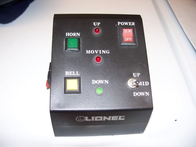
If I understand what others have said, the simplest solution is to solder wires to the two power switch terminals on the upper left.  Then run those two wires out of the box to another "beefier" switch and you're done.


OTOH, I can see how this is one cool layout accessory and if it were me, I'd really want to replace that switch so everything fits in the box and works as intended.  So, if anyone else wants to carry on the discussion, it appears the board is held "permanently" in 5 points.


1) power switch with two terminals in the upper left of photo

2) up/mid/down switch

3/4/5) up, moving, and down LEDs


ogr lift bridge switch repair


I believe the up/mid/down switch can be released from the box by un-loosening the nut.  I believe the on/off switch has to be released from the box by removing the solder from the two switch contacts of the board.   If you were extra-ordinarily lucky, the board would then come free from the box. and you could access the switch.  But the wild-card are those 3 LEDs.  It appears they used so-called "LED clips" which are shown in the inset.  Once the LED is snapped into the bezel and then the threaded black retaining ring is pressed in place, it is impossible to pull the LED out from the back without removing that retaining ring (which is really hard to do considering the angle of entry you'd have).  So if you are really ambitious, I'd say you'd have to remove the solder from the the 3 LEDs (3 x 2 = 6 connections) using copper-desoldering braid or a de-solder vacuum pump.


Yes, all this sounds very time-consuming but I really think the board can be removed though as the #1 ranked contributor to this forum will remind me, nothing is so easy as the job you imagine someone else doing. Seriously though, I believe the board could be removed in, say, 15 minutes would require soldering finesse.


Actually what I'd really like to see is the failed switch - maybe take it apart and look at the contacts or whatever.

Attachments

Images (1)
  • ogr lift bridge switch repair
Originally Posted by Dtrainmaster:

One other thing to consider before disassembly.

Thomas, you stated: ...the controller suddenly started to smell smokey...

Did you look over the bottom board for signs of overheating on any of the components? Does it smell the way you described more than the top switch-board?


Dave

Dave, to answer, the bottom board does not smell more than the top rocker switch, nor did it feel hot when I first encountered the issue.

Thomas,

Thanks so much for the pictures!


Stan,

Thanks for the analysis. I think you are spot on.


A couple of comments:

I've had good luck with adding rosin flux to a solder joint before unsoldering. The solder seems to melt at a lower temperature, which is desirable to protect the LEDs.


Reassembly could be interesting, especially for the LEDs. I wonder if it would be smarter to leave the clips off, solder the LEDs back on the board, and then insert the board into the box.


The other wild card may be the new power switch. The spacing of the terminals may not match that of the board. If it is close enough, you might be able to bend the terminals into position. Otherwise, it is probably time to relocate the switch and extend leads to the board.


Chris

LVHR

Remove the solder from all of the front panel devices and LEDs before trying to remove the board. Use either a solder-sucker tool, or copper braid designed to wick up the excess solder. Use extra flux designed for electronic work.

(You may be able to leave the switch attached if the panel-nut is removed from it first, as Stan advised)


Good luck, I want to see a video of it running when you succeed.

Dave

Last edited by Dtrainmaster

Couple more comments for anyone considering the deep-dive.


Hard to say for sure without it in front of me but as these were made 20+ years ago it looks like the circuit board may have printed-wiring on one-side only.  This would be typical for phenolic boards with "simple" circuitry.  In other words, this board simply serves as a mounting platform for the switches/LEDs and the only "electronics" on the hidden side might be 3 resistors (shown in yellow boxes) going to the 3 LEDs. 


The point is, if it's indeed a single-sided board, de-soldering the LEDs and switch will be so much easier as all the solder will be on the surface (and not throughout the hole and on the hidden side too).  Also, if resistors are the only components on the board, it makes it that much safer in that the heat from de-soldering does not damage any sensitive components.

ogr lift bridge resistors

Attachments

Images (1)
  • ogr lift bridge resistors
Last edited by stan2004

Is there a bezel around the switch on the controller cover? In other words, did the PCB board have the switches on the PCB when mounted. Or were the other switches and devices in the case. Then the board was added and soldered,


It might be possible to unsolder the switch from the PCB then pull it out the top?


Last edited by shawn

Add Reply

Post

OGR Publishing, Inc., 1310 Eastside Centre Ct, Suite 6, Mountain Home, AR 72653
800-980-OGRR (6477)
www.ogaugerr.com

×
×
×
×
Link copied to your clipboard.
×
×