Replies sorted oldest to newest
I'd run them all back to the terminal strip that feeds the track.
Be sure to phase all transformers.
Shack,
This year on my Christmas layout, I have 6 crossing gates and two gateman shanties, all driven by insulated rail Realtrax. Two separate main loops fed by 3 TIU channels.
The accessories all run on separate transformers from the track power. The gnds of all of it tie into each other. I have them after the TIU outputs, but that is just because I use barrel jacks to get the 3 Z1K bricks into the unit, and I can use a lockon and drop a wire to get a quick gnd by the accessory.
I am sure PW or other transformers could have the gnds tied before the TIU, or after, I do not see where it would make a difference.
All works well for me. I see no problem with yours working either if all is phased and gnded correctly.
Greg
Shackdaddy, there is no point in, or need to, isolate grounds between channels. In fact, they should be tied together. Note that in Rev G TIU's, they were all tied together internally. ISolation is impossible, given that trains crossing from one channel to another will make a connection, and it is best to have a solid connection via wire that a spotty and intermittent connection through wheels.
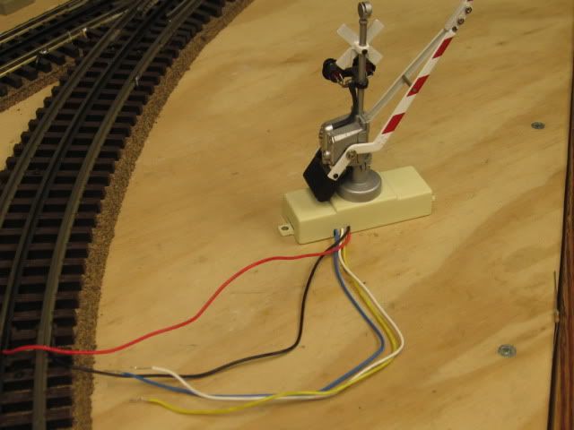
Black and Red are power to the crossing gate. Note the rail connections Black attached to the outside rail. Accessory common and Rail common one and the same.

I combine Accessory and Track common with these buss bars.
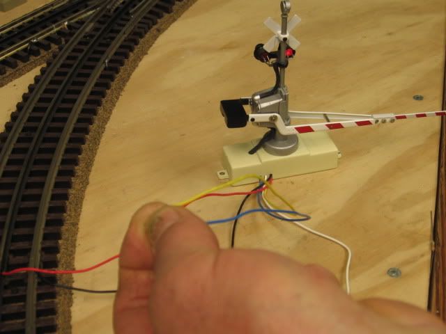
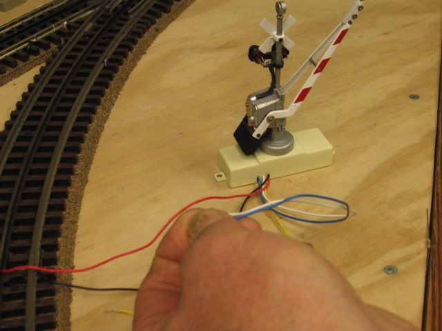
The other three wires Blue, Yellow, and White are the trip circuit for up and down.
Touch the Blue and Yellow together and the gate goes down.
Touch the Blue and White together and the gate goes up.
I use a relay board and isolated Rail section to trip the crossing gates.
Blue, yellow, and white correspond to the crossing gate trip circuit wires shown above. The third wire down from the top (Green) is the isolated rail input to the board. For this to operate the rail and accessory commons have to be one and the same. Top two wires are Relay board power Black and Red.
Mike, you introduced a variable I failed to consider...the use of the new gates that need a relay circuit to put them down, then up.
My solution was for the old style "gravity takes me up, solenoid holds me down" type gates. Hope I did not confuse him.
Thanks for posting such a concise explanation for him if he is using that style.
Greg
Your outer rails already are a common ground,you should be able to hook them together without issue. The just use a relay to activate any accessory, described here
http://www.jcstudiosinc.com/Bl...=410&categoryId=
Dale H


