I'm really enjoying the dis riptide of the engines. The S-38 is taking shape. It will be impressive when finished.
Thanks Pat. I was hoping that I didn't bore folks to death with that technical blathering.
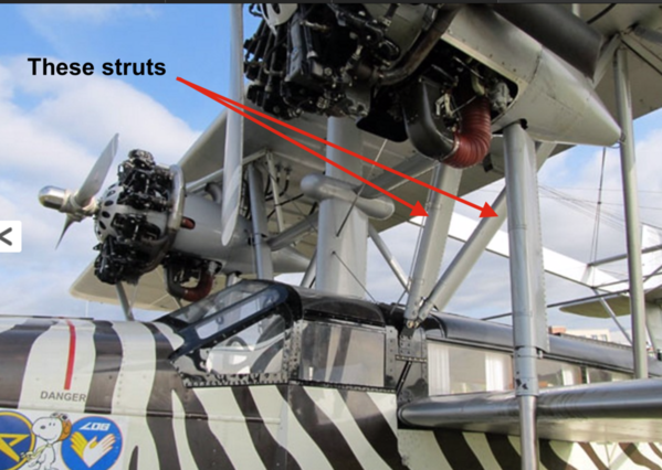
I did a major task on the S-38 today by getting those three engine struts soldered to the nacelles. It was touch and go. I didn't know if I would be able to do it and was thinking about epoxying them. At first I was trying to hold them in place while the engines were attached to the wing. I tried welding clamps pushing up on the piece, and then tried using iron wire. Nada! I took the engines off and put their crosspiece in the vice and agin tried wire. Still nada.
I then tried one more thing. I made a metal fixture to hold, loosely, the three pieces. The pins on the nacelle end anchored that end. I just needed to keep the other end in the correct geometry. While this wasn't high tech… it wasn't any tech at all, it did work.
These are solid blocks of bronze and took a long time to get to solder temperature. One of the exhaust pipes fell off, but I put that back after this was done. I did wrap the exhaust pipe with the heat block paste. It protected one of them, but not the other.
I put the engines back onto the wing to see if the struts fit at the correct angles. We'll be away until next week so that's when the struts get soldered to the wing. I will have to protect the big struts that are already in place so they don't de-solder.
Here's another view that shows the solder joints. I cleaned them up with the dremel and a dip in the ultrasonic cleaner. They will get painted and it's not a very viewable place on the plane.
There's another set of V braces that go from the main wing to the fuselage. It will not be easy, but I will solder to the wing first with the wing upside down. These plus one more that goes rearward to the fuselage need to attached to the wing before the wing can be joined to the fuse.
Attachments
That is a challenge!! You’re doing great!
It most certainly is. I have risen to the challenge and am kicking its butt.
This is a totally different modeling experience than what I'm used to. It's serious metalworking. The fact that 47 years ago I was a metal shop teacher is a good thing. I'm surprised how many things I remember even though I haven't used them for almost 50 years. Example: knocking off the sharp cutting edge on a drill when cutting brass, copper or bronze so the drill doesn't hog in and jam. Brass cutting tools require a negative rake angle. They scrape the metal off and not actually cut it. I'm also happy that I have so many metal capable tools in the shop. Without them, this job would have been a non-starter.
All the engine struts are now in place and the engines are securely soldered to the main wing. I built and installed the V-sharped mid-braces using 2-56 allen cap screws and only broke one 2-56 tap. It caused me to make an emergency trip to the hobby shop to get two more. I re-soldered one of the floats that was hanging loosely. Finally, I was able to drill out the old threads that held the mounting bolts with a "Q" drill and tapped them for an NPS 1/8-27 lamp tube thread. The Q drill was just big enough to totally remove the old threads and provide a clean surface for the new threads.
Using screws relieved me of the worry of de-soldering the struts that were right next to the mid-braces. The tap broke on the second of the four holes. I had completely tapped the hole, tried the screw in it and it didn't go deep enough. Instead of shortening the screw, I attempted to tap the hole deeper. When trying to back out the tap it jammed. Instead of freeing it, I broke it. I drilled another tap drill hole near the old one and re-tapped it successfully.
Soldering on this massive bronze structure is still quite a challenge. When it finally hits soldering temp, the entire area is hot and the solder tends to run all over the place. I wish I had that 3000 watt RSU from American Beauty.
I think my finger got into this picture.
I'm going to take the fuselage with these standoffs to the airport and fit it to the globe to make sure it goes on easily. The fuze weighs 20 pounds and is fairly easy to manipulate. The total plane weighs about 50 pounds and will be much harder to handle. I want to verify the mounting before attempting to hold the monster over the globe 8 feet in the air. Note: one of the standoffs is upside down. I just dropped them on to see if the threads were okay.
At the rate this project is going, It should be fully integrated in a couple of weeks. Then it will have to get painted.
I found out recently that the Bronx Victorian article in RMC is being moved from next month to next February (or later). The article was too long and they're no longer going to print multi-part construction features. The editor is having to do some drastic editing (earning his keep so to speak). Their new guidelines for feature articles is between 2000 to 3000 words and 10-15 images. Construction articles can be a little longer. I now have to do some drastic editing. The engine house article is already at 9,600 words with many, many images and it's not yet done. Bummer. I'm not good at writing short (as evidenced by the many thousands of words I've written in this 7 year thread). Mark Twain is credited with saying, "I have to write you a long letter since I don't have the time to write a short one." Moral: tight writing is hard.
Attachments
Couldn't take the fuselage to the airport today for the trial fitting, but I did make some more progress. Got the fuze situated on the build table and trial fit the main wing on top. I also clamped and soldered the tail back on. The tail was one part that hadn't been separated in the great fall. That responsibility fell to me. I had the wing on a couple of stools in the shop. It was behind me when I was working on my little lathe. I rolled back my desk chair and knocked the wing onto the concrete floor. The noise was horrendous and the tail was separated. Luckily, it didn't deform badly and I was able to refit it and solder it back together today. No harm, no foul. One of the struts was slightly out of position and I corrected that too.
I soldered this strut about a 1/4" to close to center and a little bit too far forward. The other struts lined up beautifully.
I modified my fixture to support the tail during the soldering operation. The tail has some 3/64" bras wire details that I need to replace. These will be easy compared to all the massive parts that needed to be reattached. Notice the model is actually supported by the fancy brass standoffs and lamp pipes. I drilled the base board so they would sink to the proper depth. I then leveled the model and level the main wing. Lines up well. I wanted to add more wood to support the outboard ends of the wings, but frankly, it wasn't needed. Even unsoldered, the diagonal struts were supporting the wing in the proper location. My build board was too narrow to move the supports out the extremis of the wing. The board is my college drawing board that I bolted to the top of an IKEA stool to make an additional work space. It's come in handy many times. It lets me work 360 degrees around the model.
With the acetylene air torch soldering has become much more predictable. It's no longer a worry. The joints are coming out relatively clean and well bonded. The repositioned strut now joints the other at the bottom end as it should.
I used some small C-clamps to lock the tail down tight, applied flux and was able to refuse the previous solder. I just had to add a little bit more to fill some more voids. There are a couple of spots that will need some filler before painting. Two are seen in this image. They're from the two pins that hold up the nacelle tapered end. I cleaned off the wing with baking soda and water to neutralize the acid flux and then went over it with some 240 grit abrasive on an oscillating multi-tool.
With a successful trial fit I'm quite confident that the entire plane will come together as it should and be quite strong. Once I got the soldering process lined out the project became must less onerous.
Attachments
Interesting, but what does this airplane have to do with the train layout?
Eddie, some posts back I asked the gang if they wanted me to continue telling them about the Sikorsky project. They said to keep going, so I did. It has absolutely nothing to do with trains per ce, but it does have to do with modeling and problem solving. These are things that folks have commented on over the last 7 years and why some of them continue to faithfully follow my musings. There's only a couple of weeks of work left on the plane and there will be railroading to follow. For example, the Fairbanks Morse locomotive diesel drawing is a finished as I'm going to make it and it ready to be 3D printed. I have a fellow who wants to buy an HO version of this beast and I'll probably produce an O'scale version too. I'm going to start designing a Baldwin engine also.
Attachments
Eddie, If you are new to Myles’ ever changing topic, I can see why you asked. I was one who voted for Myles to continue with the airplane refurbish project. If you haven’t looked back over the pages, please do. Any modeling Myles does is worth reading.
Myles, the airplane is coming along very nicely. Eddie, I too voted for Myles to post the airplane project. I find that I learn things from his technique and skill in modeling that I can apply to my train related modeling.
Miles, Since you are now a renowned expert on the Mars, is it ok if I can ask a question to improve my understanding?
Two related questions, actually:
1) As I understand it, the basic purpose of orienting the model at an angle for printing is so that you never have a larger XY cross-section on the FEP than on the top plate. There is a tug of war between the two, and you want to make sure that the plate always wins. However, I see that you often tilt items even when the shape of the model would permit the largest face to be against the plate. An example is the track bumpers. It seems to me that they could have been printed flat, and with no supports (like the Rook demo) Is there any reason to tilt them, or was it just force of habit?
2) There are cases in which you have small parts that DO have flat surfaces parallel to the plate (the lamp bases, for example), and yet they were still printed with a raft and supports. Wouldn't it be better to print such items directly on the plate?
I guess what I am really wondering is the best approach to printing long, uniform items (skinny or flat). Say I wanted to print a model of something like a railroad tie, which have uniform cross-sections in all three dimensions. Is there any reason to print such a shape at an angle with supports, or is it better to print it flat against the plate with no supports? And if the latter, is it better to put a large or a small face agains the plate?
I hope this isn't too much of a distraction, but I have been studying your model placement choices carefully, and I would like to understand completely.
Sorry for the airplane interruption, here's a video suggested to me on Youtube. Behind the scenes at Lionel.
This is the first time I have seen this thread, I understand now. I didn't read all the 72 pages.
Eddie, I’m glad you found it! Yes Myles is one of the most experienced structures modeler I have seen. He uses materials, tools, and techniques I have never seen before in my over 50 years of modeling. There is a lot to see in this topic including neat trains.
Thanks for the support folks! Eddie, if you have the time and the inclination please start at the beginning. The real beginning starts here:
https://ogrforum.ogaugerr.com/...-vs-old-build-thread
It covers the first year of the Saga in the Layout Design Forum starting with the an empty room, painting the walls, covering the ceiling, building the L-girder structure, and then laying track and wiring to get a functioning layout. Part II picks up in this forum and goes from Ballasting to the present day. There are many deviations since I don't work in a linear fashion, periodically digressing to build a plastic kit here and there just to break the monotony. Over the years I've had some steady followers and have learned as much from them as they claim they've learned from me.
Today I did get the fuselage onto the bronze globe for its fitting. It was a good idea to try it out without another 30 pounds of plane hanging on it. It took two of us, me and Jeff Smith (a pilot, architect and member of the Bowman Field Heritage Team) to maneuver it into position and I did have to drill out all three holes in the bronze dome. I broke the cutting edges of the drill so it was shaped better for drilling in brass/bronze. The model will now slip in place when it's complete. The top of the dome is over 7 feet in the air.
Re: the Mars.
Yes! Putting it on a bias is primarily to limit the contact area to the FEP film. And yes, there are some shapes where maybe situating it flat on the platen might work better. I'm relatively new to this, so it's not quite the expert leading the novice. It's more like a lessor novice leading a newer novice. That said, I also consider positioning faces with more critical details downward so the supports don't make too much of a mess. I also look at hollowed out shapes and want them facing down so the uncured resin drains out of them before I pull them off the machine. I'm trying to remember why I situated the bumpers as I did, but it probably was a compromise of the variables as I saw it at the time. There is no hard and fast rules. The other thing I'm looking at is the supports and where they're attaching themselves. If there are too many on sensitive areas where removal would damage the details I try to reposition. In other words, it all depends...
Attachments
I did the first print of the HO version of the FM Loco Primer Mover. Some parts worked well. others not as good. The problem was where I had the supports. I had the engine bottom facing down to promote drainage of the uncured resin, but this put all the supports right on top of all the delicate hatch details on the top crank cover. I tried to remove remnants, but did a lot of damage to the details. I'm reprinting it in a reversed position. Notice though how fantastically the Machine printed those tiny hand grabs on the injector covers. They are tiny. If HO rendered this well, imagine how the O'scale version will look.
The front pump cover came out okay.
The exhaust stacks didn't do so well and I'm reprinting them in a different orientation also. It's never the printer's fault. It's always how you situate parts on the machine.
S-38
Today was a big deal day. I finished putting the last of the support struts on the fuselage. The wing end is soldered. The fuze end was fastened with a 2-56 cap screw into a hole that I drilled and tapped. These six center struts were strong enough to support the fuselage weight. I was able to lift the 50 pound beast up from the build table and set it on the arms of our old knock-off Eames chair, but I am not able to lift it, hold it and position it onto the build table right side up.
To do the great reversion I enlisted the help of my daily-growing, 15 year-old grandson. He came over tonight and we were able to turn it and set it properly onto the build table. I've started doing the final cleaning and finishing in preparation for painting. I also added the hanging brace that suspends the tail of the fuselage from the tail booms. This piece is steel wire and replaces another piece of steel wire. We had to cut that wire to release the fuselage from the wing when we removed it from the memorial. All of the rest of the struts (the hot glued ones) had let go and only this wire was holding the mess together. I was pleased that the piece I made ended up being the same length as the wire it replaced indicating that the geometry was still pretty good. Tying the main struts to the lower wing are only four or five more solder joints needed to finish the job. There are some non-load-bearing cross wires that go between the tail booms. I'm going to epoxy these instead of soldering because of their proximity to the hanging brace.
Now that it's sitting correctly I find that one strut on one side is a bit long (about 3/32") and on the other side it's a bit short. It wouldn't be hard to de-solder and move the mounting position, but I can't do that with the model in this orientation. It's hard enough to solder this model. It would be near impossible to solder upside down. So I'm going to trim the long one in situ, and either shim the other with a piece of brass or just tie it to the small wing slightly separated from the other strut. The model is over seven feet in the air so no one will ever see the upper surfaces of the small wings.
I epoxied the landing gear so they're ready for paint too. I'm painting them separately and will epoxy them to the plane when it's actually on the dome. They're delicate and will most certainly be destroyed when we're attempting to maneuver the model into position. The props also will go on at the end. This is like my other scratch-build projects. There are no instructions. Much of the thinking is building things in your head to determine the best sequence to do something. You don't want to find yourself having to take something apart to put something in that should have been done before. It's probably the most gratifying part of the job. Someone gives you a beat up piece of junk and a box of unlabeled parts and you have to make it something good. I imagine that a battlefield surgeon is faced with this kind of challenge all the time. What to do before what to get maximum benefit and minimum collateral damage.
The Heritage Team did not believe that the model could be recreated. It's truly a phoenix. Until I solved the solder heat problem I wasn't so sure it was doable either. They are very pleased!
Attachments
The S-38 is mechanically done. I tied the main struts to the small wings. I fixed the slight length deviations by trimming the long one and adding a little chunk of brass under the slightly short one. This was a much easier solution than turning model over again, de-soldering and re-soldering the errant struts in a different position. I also added the cross wires on the tail booms and with that the model was complete. I did some more heavy cleaning. There's still some more to do before painting, but I need to get the right weather since it has to be either outside or in the garage.
Props are not glued in. That'll wait until the model is in final position on the memorial.
Finally was able to make respectable solder joints. I guess I need to do another to use my newly refined skills.
The model is very heavy (50 pounds), but quite strong. It will last a long time as long as no one drops it from seven feet in the air onto concrete. With the new mounting system I'm employing, it will not fall down.
It would be nice to keep it natural bronze, but the landing gear are going to have to be painted. So I'm painting the whole thing.
The Bowman Field Heritage Team is very happy with the outcome and they really didn't think it would happen. I wasn't sure it would either. They're planning a big deal for the memorial re-dedication, including newspapers and a presentation by me at the Louisville Filson Historical Society.
So gang, thanks for bearing with me on this diversion. I'm going to get back to the engine house and do the site improvements, fix that strip of LEDs that aren't full brightness and keep working on the machine shop. I'm also planning the next project. Could be the Rick House under construction next to the distillery or the coal mine. I also have another plastic kit on reserve at the hobby shop. It's the Airfix 1:24 scale Hawker Typhoon. I want to build that kit predominantly for the fabulous model of the Napier Saber 24 cylinder double boxer engine that powered it.
I had a successful reprint of the Fairbanks Morse cylinder block. By inverting how it was situated for printing, the highly detail upper crankcase printed perfectly. I still have to remove all the supports, but it should work out fine. You can see the bolts surrounding each hatch. Remember, this in in HO. I've finished the slicing for the O'scale version. If the HO version printed correctly, the O'scale version should be good too. It's too big to do it in one go. In fact, it will take four print sessions. Lost a couple of those microscopic handles, but the fuel filters came out perfect.
Attachments
THE S-38 looks fantastic, Myles. Nice job. It's amazing the detail you can get on that HO engine.
Thanks Pat! I'm not going to print the O'scale version just yet. I don't need an FM engine on my layout since I have no FM diesels in my roster. I am, however, going to design and print a Baldwin engine about which I have some very good builder's photos on which to base the model.
The HO FM Engine is ready to glue together. I cleaned up the reprinted block and exhaust stacks and then took this picture. A local fellow is buying this one. I'm well underway designing the Baldwin 1000. This one's going to be turbo-charged just because it's more interesting.
Attachments
The FM engine is complete and ready for delivery. It will have to wait until the person receives back surgery. That will take place in November. The engine came out very nicely. This is premiered. Painting and weathering would really pff it up.
I'm not going to print an O'scale version unless someone wants one. I don't have an FM engine (yet) so an FM prime mover would be out of character. I do have a Baldwin so I will be producing that engine in O'scale and HO.
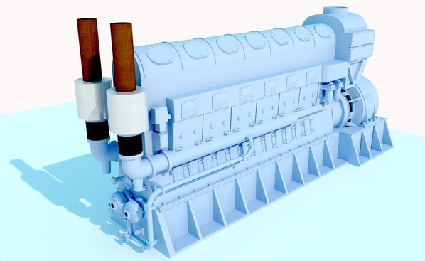
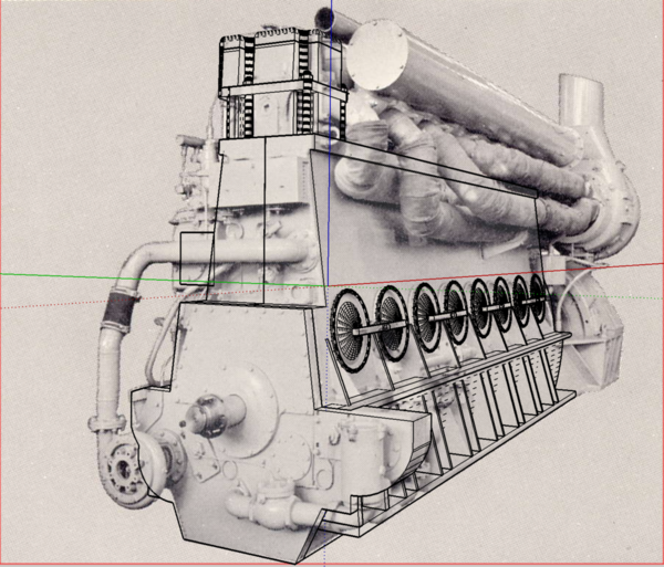
The Baldwin is going to turbo-charged and here's a screen shot of the progress. The black lines are my work overlayed over the actual images of the engine. I'm challenged getting the true contours of the cylinder heads. SketchUp doesn't like compound curves very much… at least it doesn't like how I try to draw compound curves.
Some aspects of the Baldwin engines are easier to draw than EMD, others… not so much. I need to get some imagery of the turbo end of the engine. Right now, this is the only view I have.
I also moved the S-38 to my photo table after I cleaned off all the detritus and debris left over from the reconstruction and then I took these pictures. It is definitely going to be left in natural metal. I was mixing paint to match the bronze so I can paint the landing gear and props in a more realistic match.
The color is Tamiya Gold, Tamiya Clear Red and some Tamiya Flat White. I can adjust them to get it even closer. This was my first attempt. There is definitely red in the color, but not as much as copper. This is not the wheel that's going on the model. It was a spare that I printed. My sister, the antique dealer, said, "Don't clear coat it!" I brush painted the test paint. I will airbrush the actual gear.


